1
SUPER
®
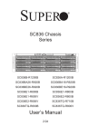
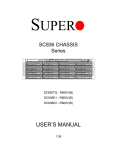
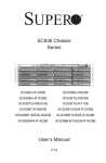
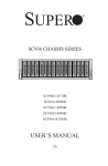
SC836 Chassis
Series
SC836A-R1200B
SC836E1-R800B
SC836E1-R800V
SC836E2-R800B
SC836E2-R800V
SC836S2-R800B
SC836S2-R800V
SC836TQ-R710B
SC836TQ - R800B
SC836TQ-R800V
User’s Manual
2.0c
SC836 Chassis Manual
The information in this User’s Manual has been carefully reviewed and is believed to be accurate.
The vendor assumes no responsibility for any inaccuracies that may be contained in this document,
makes no commitment to update or to keep current the information in this manual, or to notify any
person or organization of the updates. Please Note: For the most up-to-date version of this
manual, please see our web site at www.supermicro.com.
Super Micro Computer, Inc. ("Supermicro") reserves the right to make changes to the product
described in this manual at any time and without notice. This product, including software, if any,
and documentation may not, in whole or in part, be copied, photocopied, reproduced, translated or
reduced to any medium or machine without prior written consent.
IN NO EVENT WILL SUPERMICRO BE LIABLE FOR DIRECT, INDIRECT, SPECIAL, INCIDENTAL,
SPECULATIVE OR CONSEQUENTIAL DAMAGES ARISING FROM THE USE OR INABILITY TO
USE THIS PRODUCT OR DOCUMENTATION, EVEN IF ADVISED OF THE POSSIBILITY OF
SUCH DAMAGES. IN PARTICULAR, SUPERMICRO SHALL NOT HAVE LIABILITY FOR ANY
HARDWARE, SOFTWARE, OR DATA STORED OR USED WITH THE PRODUCT, INCLUDING THE
COSTS OF REPAIRING, REPLACING, INTEGRATING, INSTALLING OR RECOVERING SUCH
HARDWARE, SOFTWARE, OR DATA.
Any disputes arising between manufacturer and customer shall be governed by the laws of Santa
Clara County in the State of California, USA. The State of California, County of Santa Clara shall
be the exclusive venue for the resolution of any such disputes. Super Micro's total liability for all
claims will not exceed the price paid for the hardware product.
California Best Management Practices Regulations for Perchlorate Materials: This Perchlorate
warning applies only to products containing CR (Manganese Dioxide) Lithium coin cells. “Perchlorate
Material-special handling may apply. See www.dtsc.ca.gov/hazardouswaste/perchlorate”
WARNING: Handling of lead solder materials used in this
product may expose you to lead, a chemical known to
the State of California to cause birth defects and other
reproductive harm.
Manual Revision 2.0c
Release Date: February 4, 2010
Unless you request and receive written permission from Super Micro Computer, Inc., you may not
copy any part of this document.
Information in this document is subject to change without notice. Other products and companies
referred to herein are trademarks or registered trademarks of their respective companies or mark
holders.
Copyright © 2010 by Super Micro Computer, Inc.
All rights reserved.
Printed in the United States of America
ii
Preface
Preface
About This Manual
This manual is written for professional system integrators and PC technicians. It
provides information for the installation and use of the SC836 3U chassis. Installation and maintenance should be performed by experienced technicians only.
Supermicro’s SC836 3U chassis features a unique and highly optimized design for
dual-core Xeon platforms. The chassis is equipped with a redundant 710W, 800W
or 1200W high-efficiency power supply. High-performance fans provide ample optimized cooling for FB-DIMM memory modules and 16 hot-swap drive bays offers
maximum storage capacity in a 3U form factor.
This document lists compatible parts available when this document was published.
Always refer to the our Web site for updates on supported parts and configurations.
iii
SC836 Chassis Manual
Manual Organization
Chapter 1: Introduction
The first chapter provides a checklist of the main components included with the
SC836 chassis and describes the main features of the chassis. This chapter also
includes contact information.
Chapter 2: System Safety
This chapter lists warnings, precautions, and system safety. You should thoroughly
familiarize yourself with this chapter for a general overview of safety precautions
that should be followed before installing and servicing this chassis.
Chapter 3: Chassis Components
Refer here for details on this chassis model including the fans, bays, airflow shields,
and other components.
Chapter 4: System Interface
This chapter provides details on the system interface, which includes the functions
and information provided by the control panel on the chassis as well as other LEDs
located throughout the system.
Chapter 5: Chassis Setup and Maintenance
Refer to this chapter for detailed information on this chassis. You should follow the
procedures given in this chapter when installing, removing, or reconfiguring your
chassis.
Chapter 6: Advanced Setup
This chapter includes detailed instructions for advanced setup configurations including multiple chassis connections.
Chapter 7: Rack Installation
Refer to this chapter for detailed information on chassis rack installation. You should
follow the procedures given in this chapter when installing, removing or reconfiguring
your chassis into a rack environment.
iv
Preface
Compatible Backplanes
This section lists compatible cables, power supply specifications, and compatible
backplanes. Not all compatible backplanes are listed. Refer to our Web site for the
latest compatible backplane information.
Appendix A SC836 Chassis Cables
Appendix B SC836 Power Supply Specifications
Appendix C SAS-836EL Series Backplane Specifications
Appendix D SAS-836TQ Backplane Specifications
Appendix E SAS-836A Backplane Specifications
Appendix F PCC-JBWR2 and CSE-PTJBOD-CB1 Power Control
Card Specifications
v
SC836 Chassis Manual
Table of Contents
Chapter 1 Introduction
1-1
Overview.......................................................................................................... 1-1
1-2
Shipping List..................................................................................................... 1-2
Part Numbers................................................................................................... 1-2
1-3
Chassis Features............................................................................................. 1-3
CPU Support.................................................................................................... 1-3
I/O Expansion slots.......................................................................................... 1-3
Peripheral Drives.............................................................................................. 1-3
Other Features................................................................................................. 1-3
1-4
Contacting Supermicro..................................................................................... 1-4
1-5
Returning Merchandise for Service................................................................. 1-5
Chapter 2 System Safety
2-1
Overview.......................................................................................................... 2-1
2-2
Warnings and Precautions............................................................................... 2-1
2-3
Preparing for Setup.......................................................................................... 2-1
2-4
Electrical Safety Precautions........................................................................... 2-2
2-5
General Safety Precautions............................................................................. 2-3
2-6
System Safety.................................................................................................. 2-3
Chapter 3 Chassis Components
3-1
Overview.......................................................................................................... 3-1
3-2
Components..................................................................................................... 3-1
Chassis and Chassis Bays.............................................................................. 3-1
Backplane......................................................................................................... 3-1
Fans................................................................................................................. 3-1
Mounting Rails................................................................................................. 3-1
Power Supply................................................................................................... 3-2
Air Shroud........................................................................................................ 3-2
3-3
Where to get Replacement Components......................................................... 3-2
Chapter 4 System Interface
4-1
Overview.......................................................................................................... 4-1
4-2
Control Panel Buttons...................................................................................... 4-2
4-3
Control Panel LEDs......................................................................................... 4-2
4-4
Drive Carrier LEDs........................................................................................... 4-4
Chapter 5 Basic Chassis Setup and Maintenance
5-1
Overview.......................................................................................................... 5-1
5-2
Installation........................................................................................................ 5-1
vi
Preface
5-3
Removing the Chassis Cover.......................................................................... 5-2
5-4
Installing the Hard Drives................................................................................. 5-3
Removing Hard Drive Carriers from the Chassis............................................ 5-3
Installing a Hard Drive to the Hard Drive Carrier............................................ 5-3
5-5
Installing the Motherboard............................................................................... 5-5
Permanent and Optional Standoffs.................................................................. 5-5
Standoffs Labeling........................................................................................... 5-5
Motherboard Installation................................................................................... 5-5
Power Supply Connections.............................................................................. 5-6
I/O Shield and Expansion Card Setup............................................................. 5-7
Installing an I/O Port Panel.............................................................................. 5-7
Installing an Expansion Card........................................................................... 5-8
5-6
Installing the Air Shroud, Rear Fan, and Checking Air Flow........................... 5-9
Installing the Air Shroud................................................................................... 5-9
Installing Rear System Fans.......................................................................... 5-10
Checking the Server's Air Flow.......................................................................5-11
5-7
Chassis Maintenance..................................................................................... 5-12
Replacing a System Fans.............................................................................. 5-12
Replacing the Power Supply.......................................................................... 5-13
Replacing the Power Distributor.................................................................... 5-14
Replacing the Front Panel............................................................................. 5-15
Replacing or Installing the Front Port Panel.................................................. 5-15
Chapter 6 Advanced Setup
6-1
Overview.......................................................................................................... 6-1
6-2
Dual Port and Expanders................................................................................. 6-2
Single Ports...................................................................................................... 6-2
Dual Ports........................................................................................................ 6-2
6-3
Failover............................................................................................................. 6-3
Single Host Bus Adapter.................................................................................. 6-3
Single Host Bus Adapter Failover.................................................................... 6-3
Dual Host Bus Adapter ................................................................................... 6-4
Dual Host Bus Adapter Failover...................................................................... 6-4
6-4
Cascading Backplanes..................................................................................... 6-4
Power Control Card......................................................................................... 6-4
Chapter 7 Rack Installation
7-1
Overview.......................................................................................................... 7-1
7-2
Unpacking the System..................................................................................... 7-1
7-3
Preparing for Setup.......................................................................................... 7-1
vii
SC836 Chassis Manual
Choosing a Setup Location.............................................................................. 7-1
7-4
Warnings and Precautions............................................................................... 7-2
Rack Precautions............................................................................................. 7-2
General Server Precautions............................................................................. 7-2
7-5
Rack Mounting Considerations........................................................................ 7-3
Ambient Operating Temperature...................................................................... 7-3
Reduced Airflow............................................................................................... 7-3
Mechanical Loading......................................................................................... 7-3
Circuit Overloading........................................................................................... 7-3
Reliable Ground............................................................................................... 7-3
7-6
Rack Mounting Instructions.............................................................................. 7-4
Identifying the Sections of the Rack Rails....................................................... 7-4
Locking Tabs.................................................................................................... 7-5
Releasing the Inner Rail.................................................................................. 7-5
Installing The Inner Rails on the Chassis........................................................ 7-6
Installing the Outer Rails on the Rack............................................................. 7-7
Standard Chassis Installation.......................................................................... 7-8
Optional Quick Installation Method.................................................................. 7-9
Appendix A SC836 Chassis Cables
Appendix B SC836 Power Supply Specifications
Appendix C SAS-836EL Backplane Specifications
Appendix D SAS-836TQ Backplane Specifications
Appendix E SAS-836A Backplane Specifications
Appendix F PCC-JBPWR2 and CSE-PTJBOD-CB1 Power Control Card
Specifications
viii
Chapter 1: Introduction
Chapter 1
Introduction
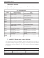
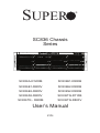
1-1 Overview
Supermicro's SC836 storage chassis supports up to sixteen hot-swappable 3.5"
SAS/SATA hard drive bays, the industry's highest storage density for a 3U system.
The SC836 includse 100% cooling redundancy and high efficiency (1+1) redundant
710W, 800W, or 1200W (93%) Gold Level power supplies with PM BUS functionality
for enhanced power management. The SC836 is optimized for the next-generation
dual-processor Intel® Xeon® (5500 series) and AMD Opteron™ platforms. Direct
attached HDD backplane (TQ version), multilane backplane (A version) and expanders' backplane (E1, E2 versions) are available for application specific solution
optimization. Heavy duty palletized packaging is available to ensure secure system
reliability during shipping and tool-less, roller rail designs for easy installation and
maintenance are standard with each system.
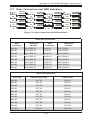
SC836 Chassis Series
CPU
HDD
I/O Slots
Power
Supply
SC836A-R1200B
DP/UP
16x SAS / SATA
7x FF
1200W
Redundant
(Gold Level)
SC836TQ-R800V /
SC836TQ-R800B
DP/UP
7x FF
R800W
Redundant
SC836TQ-R710B
DP/UP
16x SAS / SATA
7x FF
710W DC
Redundant
SC836S2-R800V /
SC836S2-R800B
DP/UP
16x U320 SCSI
Dual Channel
7x FF
800W
Redundant
SC836E1-R800V /
SC836E1-R800B
DP/UP
16x SAS / SATA
Bays (+) 1x
28-Port SAS
Expander
7x FF
R800W
Redundant
DP/UP
16x SAS / SATA
Bays (+) 2x
28-Port SAS
Expander
7x FF
800W
Redundant
Model
SC836E2-R800V /
SC836E2-R800B
16x SAS / SATA
1-1
SC836 Chassis Manual
1-2 Shipping List
Part Numbers
Please visit the following link for the latest shipping lists and part numbers for
your particular chassis model:
http://www.supermicro.com/products/chassis/3U/?chs=836
1-2
Chapter 1: Introduction
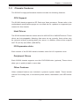
1-3 Chassis Features
The SC836 3U high-performance chassis includes the following features:
CPU Support
The SC836 chassis supports a DP Dual-core Xeon processor. Please refer to the
motherboard specifications pages on our Web site for updates on supported processors for this chassis
Hard Drives
The SC836 chassis features sixteen slots for U320 SCSI or SAS/SATA drives. These
drives are hot-swappable. Meaning thtat once set up correctly, these drives may
be removed without powering-down the server. In addition, these drives support
SAF-TE (SCSI) and SES2 (SAS/SATA).
I/O Expansion slots
Each version of the SC836 chassis includes seven full I/O expansion slots.
Peripheral Drives
Each SC836 chassis supports one slim DVD-ROM drive (optional) These drives
allow you to quickly install or save data.
Other Features
Other onboard features are included to promote system health. These include
various five cooling fans, a convenient power switch, reset button, and LED indicators.
1-3
SC836 Chassis Manual
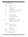
1-4 Contacting Supermicro
Headquarters
Address:
Super Micro Computer, Inc.
980 Rock Ave.
San Jose, CA 95131 U.S.A.
Tel:
+1 (408) 503-8000
Fax:
+1 (408) 503-8008
Email:
[email protected] (General Information)
[email protected] (Technical Support)
Web Site:
www.supermicro.com
Europe
Address:
Super Micro Computer B.V.
Het Sterrenbeeld 28, 5215 ML
's-Hertogenbosch, The Netherlands
Tel:
+31 (0) 73-6400390
Fax:
+31 (0) 73-6416525
Email:
[email protected] (General Information)
[email protected] (Technical Support)
[email protected] (Customer Support)
Asia-Pacific
Address:
Super Micro Computer, Inc.
4F, No. 232-1, Liancheng Rd.
Chung-Ho 235, Taipei County
Taiwan, R.O.C.
Tel:
+886-(2) 8226-3990
Fax:
+886-(2) 8226-3991
Web Site:
www.supermicro.com.tw
Technical Support:
Email:
[email protected]
Tel: 886-2-8226-1900
1-4
Chapter 1: Introduction
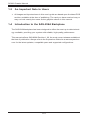
1-5 Returning Merchandise for Service
A receipt or copy of your invoice marked with the date of purchase is required before any warranty service will be rendered. You can obtain service by calling your
vendor for a Returned Merchandise Authorization (RMA) number. When returning
to the manufacturer, the RMA number should be prominently displayed on the
outside of the shipping carton, and mailed prepaid or hand-carried. Shipping and
handling charges will be applied for all orders that must be mailed when service
is complete.
For faster service, RMA authorizations may be requested online (http://www.
supermicro.com/support/rma/).
Whenever possible, repack the chassis in the original Supermicro carton, using the
original packaging material. If these are no longer available, be sure to pack the
chassis securely, using packaging material to surround the chassis so that it does
not shift within the carton and become damaged during shipping.
This warranty only covers normal consumer use and does not cover damages incurred in shipping or from failure due to the alteration, misuse, abuse or improper
maintenance of products.
During the warranty period, contact your distributor first for any product problems.
1-5
Chapter 2: System Safety
Chapter 2
System Safety
2-1 Overview
This chapter provides a quick setup checklist to get your chassis up and running.
Following the steps in order given should enable you to have your chassis setup and
operational within a minimal amount of time. These instructions assume that you are
an experienced technician, familiar with common concepts and terminology.
2-2 Warnings and Precautions
You should inspect the box the chassis was shipped in and note if it was damaged
in any way. If the chassis itself shows damage, file a damage claim with the carrier
who delivered your system.
Decide on a suitable location for the rack unit that will hold the chassis. It should be
situated in a clean, dust-free area that is well ventilated. Avoid areas where heat,
electrical noise and electromagnetic fields are generated.
You will also need it placed near at least two grounded power outlets. The SC836
chassis includes two redundant power supplies which require two grounded outlets.
2-3 Preparing for Setup
The SC836 chassis includes a set of rail assemblies, including mounting brackets
and mounting screws you will need to install the systems into the rack. Please read
this manual in its entirety before you begin the installation procedure.
2-1
SC836 Chassis Manual
2-4 Electrical Safety Precautions
Basic electrical safety precautions should be followed to protect yourself from harm
and the SC836 from damage:
•Be aware of the locations of the power on/off switch on the chassis as well
as the room’s emergency power-off switch, disconnection switch or electrical
outlet. If an electrical accident occurs, you can then quickly remove power from
the system.
•Do not work alone when working with high voltage components.
•Power should always be disconnected from the system when removing or in-
stalling main system components, such as the serverboard, memory modules
and the DVD-ROM (not necessary for hot-swappable drives). When disconnecting power, you should first power down the system with the operating
system and then unplug the power cords from all the power supply modules
in the system.
•When working around exposed electrical circuits, another person who is fa-
miliar with the power-off controls should be nearby to switch off the power, if
necessary.
•Use only one hand when working with powered-on electrical equipment. This
is to avoid making a complete circuit, which will cause electrical shock. Use
extreme caution when using metal tools, which can easily damage any electrical
components or circuit boards they come into contact with.
•Do not use mats designed to decrease electrostatic discharge as protection from
electrical shock. Instead, use rubber mats that have been specifically designed
as electrical insulators.
•The power supply power cord must include a grounding plug and must be
plugged into grounded electrical outlets.
•Serverboard battery: CAUTION - There is a danger of explosion if the onboard
battery is installed upside down, which will reverse its polarities This battery
must be replaced only with the same or an equivalent type recommended by
the manufacturer. Dispose of used batteries according to the manufacturer’s
instructions.
2-2
Chapter 2: System Safety
•Please handle used batteries carefully. Do not damage the battery in any way;
a damaged battery may release hazardous materials into the environment. Do
not discard a used battery in the garbage or a public landfill. Please comply
with the regulations set up by your local hazardous waste management agency
to dispose of your used battery properly.
•DVD-ROM laser: CAUTION - this server may have come equipped with a
DVD-ROM drive. To prevent direct exposure to the laser beam and hazardous
radiation exposure, do not open the enclosure or use the unit in any unconventional way.
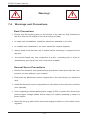
2-5 General Safety Precautions
•Keep the area around the chassis clean and free of clutter.
•Place the chassis top cover and any system components that have been re-
moved away from the system or on a table so that they won’t accidentally be
stepped on.
•While working on the system, do not wear loose clothing such as neckties and
unbuttoned shirt sleeves, which can come into contact with electrical circuits or
be pulled into a cooling fan.
•Remove any jewelry or metal objects from your body, which are excellent metal
conductors that can create short circuits and harm you if they come into contact
with printed circuit boards or areas where power is present.
•After accessing the inside of the system, close the system back up and secure
it to the rack unit with the retention screws after ensuring that all connections
have been made.
2-6 System Safety
Electrostatic discharge (ESD) is generated by two objects with different electrical
charges coming into contact with each other. An electrical discharge is created to
neutralize this difference, which can damage electronic components and printed
circuit boards. The following measures are generally sufficient to neutralize this
difference before contact is made to protect your equipment from ESD:
•Do not use mats designed to decrease electrostatic discharge as protection from
electrical shock. Instead, use rubber mats that have been specifically designed
as electrical insulators.
2-3
SC836 Chassis Manual
•Use a grounded wrist strap designed to prevent static discharge.
•Keep all components and printed circuit boards (PCBs) in their antistatic bags
until ready for use.
•Touch a grounded metal object before removing any board from its antistatic
bag.
•Do not let components or PCBs come into contact with your clothing, which may
retain a charge even if you are wearing a wrist strap.
•Handle a board by its edges only; do not touch its components, peripheral chips,
memory modules or contacts.
•When handling chips or modules, avoid touching their pins.
•Put the serverboard and peripherals back into their antistatic bags when not
in use.
•For grounding purposes, make sure your computer chassis provides excellent
conductivity between the power supply, the case, the mounting fasteners and
the serverboard.
2-4
Chapter 3: Chassis Components
Chapter 3
Chassis Components
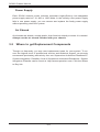
3-1 Overview
This chapter describes the most common components included with your chassis.
Some components listed may not be included or compatible with your particular
chassis model. For more information, see the installation instructions detailed later
in this manual.
3-2 Components
Chassis and Chassis Bays
Chassis may include one optional slim CD-ROM or DVD-ROM, one front port panel,
and 16 hard drive bays. Hard drives must be purchased separately. For the latest
shipping lists, visit our Web site at: http://www.supermicro.com.
Backplane
Each SC836 chassis comes with a 3U backplane. Depending upon your order,
your backplane will accept SAS/SATA drives, SAS only, or SCSI drives. For more
information regarding compatible backplanes, view the appendices found at the
end of this manual. In addition, visit our Web site for the latest information: http://
www.supermicro.com.
Fans
The SC836 chassis accepts five system fans. System fans for SC836 chassis are
powered from the serverboard. These fans are 3U compatible and are powered by
3-pin connectors.
Mounting Rails
The SC836 can be placed in a rack for secure storage and use. To setup your rack,
follow the step-by-step instructions included in this manual.
3-1
SC836 Chassis Manual
Power Supply
Each SC836 chassis model includes redundant high-efficiency hot-swappable
power supply rated at 710, 800 or 1200 Watts. In the unlikely event power supply
fails in one power supply, you can remove and replace the faulty power supply
without powering down the system.
Air Shroud
Air shrouds are shields, usually plastic, that funnel air directly to where it is needed.
Always use the air shroud included with your chassis.
3-3 Where to get Replacement Components
Though not frequently, you may need replacement parts for your system. To ensure the highest level of professional service and technical support, we strongly
recommend purchasing exclusively from our Supermicro Authorized Distributors /
System Integrators / Resellers. A list of Supermicro Authorized Distributors / System
Integrators /Reseller can be found at: http://www.supermicro.com. Click the Where
to Buy link.
3-2
Chapter 4: System Interface
Chapter 4
System Interface
4-1 Overview
There are several LEDs on the control panel as well as others on the drive carriers
to keep you constantly informed of the overall status of the system as well as the
activity and health of specific components. Most SC836 models have two buttons
on the chassis a control panel- a reset button and an on/off switch. This chapter
explains the meanings of all LED indicators and the appropriate response you may
need to take.
Figure 4-1: SC836 Front Panel
4-1
SC836 Chassis Manual
4-2 Control Panel Buttons
There are two push-buttons located on the front of the chassis. These are (in order
from left to right) a reset button and a power on/off button.
•Reset: The reset button is used to reboot the system.
•Power: The main power switch is used to apply or remove power from the
power supply to the server system. Turning off system power with this button
removes the main power but keeps standby power supplied to the system.
Therefore, you must unplug system before servicing.
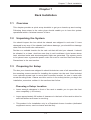
4-3 Control Panel LEDs
The control panel located on the front of the SC836 chassis has 6 LEDs. These
LEDs provide you with critical information related to different parts of the system.
This section explains what each LED indicates when illuminated and any corrective
action you may need to take.
!
•Power Failure: When this LED flashes, it indicates a power failure in the
power supply.
4-2
Chapter 4: System Interface
•Overheat/Fan Fail: When this LED flashes it indicates a fan failure. When
continuously on (not flashing) it indicates an overheat condition, which may be
caused by cables obstructing the airflow in the system or the ambient room
temperature being too warm. Check the routing of the cables and make sure
all fans are present and operating normally. You should also check to make
sure that the chassis covers are installed. Finally, verify that the heatsinks are
installed properly. This LED will remain flashing or on as long as the overheat
condition exists.
•NIC2: Indicates network activity on LAN2 when flashing.
•NIC1: Indicates network activity on LAN1 when flashing.
•HDD: Indicates IDE channel activity. SAS/SATA drive, SCSI drive, and/or
DVD-ROM drive activity when flashing.
•Power: Indicates power is being supplied to the system's power supply units.
This LED should normally be illuminated when the system is operating.
4-3
SC836 Chassis Manual
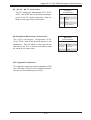
4-4 Drive Carrier LEDs
Each SAS drive carrier has two LEDs.
•Blue: When illuminated, this blue LED (on the front of the drive carrier) indicates
drive activity. A connection to the SAS backplane enables this LED to blink on
and off when that particular drive is being accessed.
•Red: The red LED to indicate a drive failure. If one of the SAS drives fail, you
should be refer to your system management software.
4-4
Chapter 5: Chassis Setup and Maintenance
Chapter 5
Basic Chassis Setup
and Maintenance
5-1 Overview
This chapter details the basic steps required to install components to the chassis.
The only tool you will is a Phillips screwdriver. Print this page to use as a reference
while setting up your chassis.
When coupled with an 836E series backplane, this chassis is capable of failover,
and cascading. Review Chapter 6 and the SAS-836EL appendix in this manual for
setup instructions.
5-2 Installation
Removing the Chassis Cover
Installing Hard Drives
Installing the Motherboard (Includes standoffs, I/O shield and exapansion card
installation)
Installing the Air Shroud, Rear Fan and Checking the Airflow
Chassis Maintenance (Includes replacing the system fans, power supply, power
distributor and front panel)
!
Note: The SC836E1 and SC836E2 chassis support SAS drives
only. For more information, review the SAS 836EL Backplane
Specifications located in the appendices of this document.
!
Review the warnings and precautions listed in the manual before setting up or servicing this chassis. These include information in Chapter 2: System Safety and the warning/precautions listed in the setup instructions.
5-1
SC836 Chassis Manual
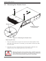
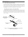
5-3 Removing the Chassis Cover
1
12
1
Release Tab
Remove this screw
(if necessary)
Figure 5-1: Removing the Chassis Cover
Removing the Cover
1. Press the release tabs to remove the cover from the locked position. Press
both tabs at the same time. If necessary, you may need to remove the chassis cover screw.
2. Once the top cover is released from the locked position, slide the cover
toward the rear of the chassis and lift the cover off the unit.
!
Warning: Except for short periods of time, do NOT operate the
server without the cover in place. The chassis cover must be in
place to allow proper airflow and prevent overheating.
5-2
Chapter 5: Chassis Setup and Maintenance
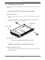
5-4 Installing the Hard Drives
The drives are mounted in drive trays to simplify their installation and removal from
the chassis.
Removing Hard Drive Carriers from the Chassis
Removing HDD Carriers
1. Press the release button on the drive carrier. This extends the drive carrier
handle.
2. Use the handle to pull the drive out of the chassis. When replacing the carrier, use the handle to lock the tray into place.
Dummy Drive
Drive Carrier
Release Button
Figure 5-2: Removing Dummy Drive from Carrier
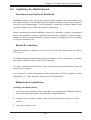
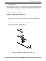
Installing a Hard Drive to the Hard Drive Carrier
Installing an HDD into a Carrier
1. Remove the screws (2) securing the dummy drive to the drive tray and separate the dummy drive.
5-3
SC836 Chassis Manual
SAS/SATA or SCSI
Hard Drive
Hard Drive
Carrier
Use a hard, stable
surface when installing
the hard drive
Figure 5-3: Installing a SAS or SATA Drive to Hard Drive Carrier
2. Place the hard drive carrier on a flat, stable surface such as a desk, table, or
work bench.
3. Slide the hard drive into the carruer with the printed circuit board side facing
down.
4. Carefully align the mounting holes in the hard drive and the carrier. Make sure
the bottom of the hard drive and bottom of the hard drive carrier are flush.
5. Secure the hard drive using all six (6) screws.
6. Replace the drive tray into the chassis. Make sure to close the drive carrier
using the drive carrier handle.
!
Warning! Enterprise level hard disk drives are recommended for
use in Supermicro chassis and servers. For information on recommended HDDs, visit the Supermicro Web site at http://www.
supermicro.com/products/nfo/files/storage/SAS-1-CompList110909.pdf
5-4
Chapter 5: Chassis Setup and Maintenance
5-5 Installing the Motherboard
Permanent and Optional Standoffs
Standoffs prevent short circuits by securing space between the motherboard and
the chassis surface. The SC836 chassis includes permanent standoffs in locations
used by most motherboards. These standoffs accept the rounded Phillips head
screws included in the SC836 accessories packaging.
Some motherboard require additional screws for heatsinks, general components
and/or non-standard security. Optional standoffs are included to these motherboards. To use an optional standoff, you must secure a hexagonal post by screwing
it into the necessary spot.
Standoffs Labeling
Standoff locations are labeled on the bottom of the SC836 chassis with the letters:
P, D, and A.
P = Most compatible motherboards have a processor or CPU located here. If necessary, place standoffs here for the CPU's heatsink.
D = Place optional standoffs here if your motherboard requires additional posts to
hold the unit in place.
A = A number of older motherboards have processors or CPUs located in areas
designated "A". Place standoffs here for the CPU's heatsink.
Motherboard Installation
Installing the Motherboard
1. Review the documentation that came with your motherboard. Become familiar
with component placement, requirements, and precautions.
2. Confirm that the power supply is disconnected and lay the chassis on a flat
surface.
3. Open the chassis cover.
5-5
SC836 Chassis Manual
4. Remove any packaging from the chassis. If the rear fans (set of two fans
nearest the I/O slots) or the air shroud is in place, remove them.
5. If required by your motherboard, install standoffs in any areas that do not
have a permanent standoff. To do this, tighten a hexagonal optional standoff
into the chassis.
6. Lay the motherboard on the chassis aligning the permanent and optional
standoffs.
7. Secure the motherboard to the chassis using the rounded, Phillips head
screws. Do not exceed eight pounds of torque per square inch when tightening down the motherboard.
8. Secure the CPU(s) and heatsinks to the motherboard.
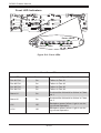
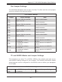
Power Supply Connections
Connect each of the following cables, as required, by your motherboard manufacturer. In some instances, some cables may not need to be connected.
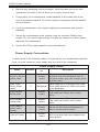
Power Supply Cables
Number
Connects
to:
Description
20-pin or 24-pin
power cable
1
Motherboard
20-pin or 24-pin power cable provides
electricity to the motherboard. Has 20 24 yellow, black, gray, red, orange, green
and blue wires.
HDD (Hard
Drive) power
cable
3
Backplane
Each cable has 3 connectors (two Hard
Drive [HDD] Attach the HDD connectors
to the backplane. .
8-pin motherboard cable
1
Motherboard
Provides power to the motherboard CPU.
This cable has 2 black and 2 yellow
wires.
4-pin motherboard cable
1
Motherboard
Provides power to PCI expansion card.
This cable has 2 black and 2 yellow
wires.
5-pin SMBus
power cable
(small)
1
Motherboard
Allows the SM (System Management)
Bus to monitor power supply
2-pin INT cable
1
Motherboard
Intrusion detection cable allows the system to log when the server chassis has
been opened.
Name
5-6
Chapter 5: Chassis Setup and Maintenance
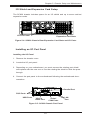
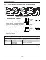
I/O Shield and Expansion Card Setup
The SC836 chassis includes space for an I/O shield and up to seven add-on/
expansion cards.
I/O Port Panel
Expansion Card Slots
Figure 5-4: SC836 Chassis Rear Expansion Card Slots and I/O Ports
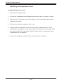
Installing an I/O Port Panel
Installing the I/O Panel
1. Remove the chassis cover.
2. Locate the I/O port panel.
3. Depending on your motherboard, you must remove the existing port shield
and replace with the new one or use the existing the shield to slide the ports
through.
4. Connect the port panel to the motherboard following the motherboard documentation.
Parallel Port
PS/2 Ports
USB Ports
VGA or
Video Port
Serial/
COM Ports
Figure 5-5: SC836 Chassis Port Panel
5-7
LAN
Port
SC836 Chassis Manual
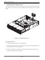
Installing an Expansion Card
Installing Expansion Cards
1. Remove the chassis cover.
2. Locate the motherboard port aligned with the card slot you want to install.
3. Each slot is secured by one screw located on the top (inside) the chassis.
Remove this screw.
4. Remove the add-on/ expansion slot cover.
5. Gently slide the expansion card into the correct motherboard slot. If the
expansion card requires a riser card, install it at this time. If necessary, slide
the card into the PCI card guide and lock. Never force a component into a
motherboard or the chassis.
6. Secure the expansion card with the screw from the I/O panel.
5-8
Chapter 5: Chassis Setup and Maintenance
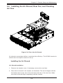
5-6 Installing the Air Shroud, Rear Fan, and Checking
Air Flow
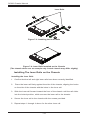
Figure 5-6: Place the Air Shroud
Air shrouds concentrate airflow to maximize fan efficiency. The SC836 chassis air
shroud does not require screws to set up.
Installing the Air Shroud
Air Shroud Installation
1. Remove the chassis cover. If necessary, remove the rear fans.
2. Place the air shroud in the chassis, as illustrated. The shroud aligns with the
fan holders and covers two of the front fans with two of the rear fans. Make
sure the air shroud aligns completely with the chassis.
5-9
SC836 Chassis Manual
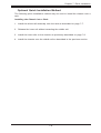
Installing Rear System Fans
The SC836 chassis includes three front fans and two rear fans. The front fans are
pre-installed. The rear fans must be installed after motherboard and air shroud
setup.
Figure 5-7: Install the Rear Fan
Installing Rear Fans
1. Confirm that the air shroud is correctly placed.
2. Slide the rear fan into the slot as illustrated. The fan release tab should be on
the side closest to the power supply.
3. Make sure that the fan is secure in the fan housing and the housing is correctly connected to the power supply.
5-10
Chapter 5: Chassis Setup and Maintenance
Checking the Server's Air Flow
Checking the Air Flow
1. Make sure there are no objects to obstruct airflow in and out of the server. If
necessary, route the cables through the cable rack.
2. Do not operate the server without drives or drive trays in the drive bays.
3. Use only recommended server parts.
4. Make sure no wires or foreign objects obstruct air flow through the chassis.
Pull all excess cabling out of the airflow path or use shorter cables.
5. Do not operate the server for extended periods of time without the air shroud
in the proper place.
5-11
SC836 Chassis Manual
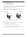
5-7 Chassis Maintenance
Replacing a System Fans
Five heavy duty fans provide cooling for the chassis. These fans circulate air through
the chassis as a means of lowering the chassis' internal temperature. The SC836
Chassis includes three front fans and two rear fans.
SC836 chassis fans are fully hotswappable. In other words, fans may be removed
and replaced without having to power down the server.
Fan Release Tab
Fan Release Tab
Front Fan (3 total)
Rear Fan (2 total)
Figure 5-8: Chassis Fans
Replacing Fans
1. Open the chassis and locate the faulty fan. Never run the server for an extended period of time with the chassis open.
2. Press the release tab on the fan and pull the fan upward.
3. Slide the new fan into the fan housing. Make sure the power connectors are
correctly aligned. The new fan will be immediately active.
5-12
Chapter 5 Chassis Setup and Maintenance
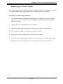
Replacing the Power Supply
The power supply for the SC836 Chassis is redundant and hot swappable, meaning
the power supply can be changed without powering down the system.
Replacing a Power Supply Module
1. The SC836 chassis includes a redundant power supply (at least two power
modules), you can leave the server running if you remove only one power
supply at a time.
2. Unplug the power supply that you will replace.
3. Push the release tab (on the back of the power supply) as illustrated.
4. Pull the power supply out using the handle provided.
5. Replace the failed power module with the same model.
6. Push the new power supply module into the power bay until you hear a click.
7. Plug the AC power cord back into the module and power up the server.
5-13
SC836 Chassis Manual
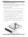
Replacing the Power Distributor
Redundant server chassis that are 2U or more in height require a power distributor.
The power distributor provides failover and power supply redundancy. In the unlikely
event you must replace the power distributor, do following
Power Distributor Replacement
1. Power-down the server and remove the plug from the wall socket or power
strip.
2. Remove all cable connections from the power supply to the motherboard,
backplane, and other components. Also, remove both power supplies.
3. Locate the power distributor between the power supply and the fan row.
4. Remove the three screws securing the power supply.
5. Gently pull the power distributor from the chassis. Make the guide all the
cables through the power distributor housing.
6. Slide the new power distributor module into the power distributor housing.
Make that you slide the cables through the bottom of the housing.
7. Reconnect all the power cables, replace the power supply, and insert the plug
into the wall.
Figure 5-9: Removing the Power Distributor
5-14
Chapter 5 Chassis Setup and Maintenance
Replacing the Front Panel
SC836 chassis models include a slim DVD-ROM, optional floppy drive and front
port panel. Use the instructions in this section in the unlikely event that you must
replace any of these components.
The front panel
goes into the
center slot
Figure 5-10: Installing the DVD-ROM, Optional Floppy Drive and Front Panel
Replacing or Installing the Front Port Panel
Installing the Front Panel
1. Power down and unplug the system.
2. Remove the chassis cover.
3. (If you are not installing a new front port panel) Remove the mini-bezel
(grate) from the drive bay The mini-bezel is the small grating that covers the
drive bay. Remove this by simply pulling it out of the bay.
(If you are installing a new front port panel) Remove the old front port
panel by depressing the release tab, then pulling the front port panel out of
the chassis.
4. Insert the new unit in the slot until the tab locks into place.
5. Connect the data and power cables to the backplane and, if necessary,
motherboard.
6. For more information, see the manual for your backplane in the appendix.
5-15
SC836 Chassis Manual
Notes
5-16
Chapter 6: Advanced Setup
Chapter 6
Advanced Setup
6-1 Overview
This chapter covers the steps required to take advantage of the dual port, failover,
and cascading features available with the SAS-836EL series backplanes.
If you are not using a SAS-836EL series backplane or you do not want to take
advantage of the advanced features, you may skip this chapter
Specific examples and cascading instructions can be found in the backplane appendices of this manual
!
Review the warnings and precautions listed in the manual before setting up or servicing this chassis. These include information in Chapter 2: System Safety and the warning/precautions listed in the setup instructions.
6-1
SC836 Chassis Manual
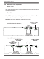
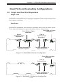
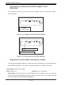
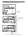
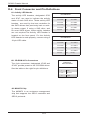
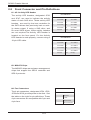
6-2 Dual Port and Expanders
Single Ports
SAS-836EL1 backplanes have a single-port expander that access all sixteen drives
and supports cascading.
Dual Ports
SAS-836EL2 backplanes have dual-port expanders that access all 16 drives. These
dual-port expanders supports cascading, failover and recovery.
Note: Both 836EL series backplanes support SAS drives only.
To HBA or higher
backplane
SAS-836E2 Single-Port Backplane
Port A
Primary Ports
PRI_J2
SEC_J2
SEC_J0
PRI_J1
SEC_J1
J1
J2
PRI_J0
J0
From Lower
Backplane in
Cascaded System
SAS-836E2 Dual-Port Backplane
To HBA or Higher
Backplane
To HBA or Higher
Backplane
Port B
Secondary Ports
Expander 2
Port A
Primary Ports
Expander 1
PRI_J2
SEC_J2
J2
SEC_J0
SEC_J1
J1 J2
J0
PRI_J1
J1
From Lower
Backplane in
Cascaded System
From Lower
Backplane in
Cascaded System
6-2
PRI_J0
J0
Chapter 6: Advanced Setup
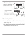
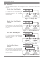
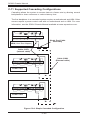
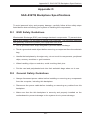
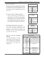
6-3 Failover
Failover is the ability to automatically switch to a redundant path when a primary
path fails or becomes unavailable. Failover is automatic and requires no action on
the part of the administrator.
The SAS-836EL2 backplane has two expanders which allow effective failover and
recovery. This feature is not supported by the SAS-836EL1 backplane.
Single Host Bus Adapter
SAS HBA
In a single host bus configuration, the
backplane connects to one Host Bus
Adapter (HBA).
PRI_J2
SEC_J2
SEC_J0
PRI_J1
SEC_J1
PRI_J0
WWN
Port B
J0
Expander 2
Port A
J0
Expander 1
J17
Single Host Bus Adapter
Failover
SAS HBA
PRI_J2
SEC_J2
SEC_J0
PRI_J0
Port B
Expander 2
J17
6-3
PRI_J1
SEC_J1
WWN
If the eExpander or data path in Port A
fails, the system will automatically fail
over to Port B.
Port A
Expander 1
SC836 Chassis Manual
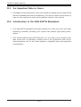
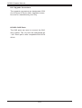
Dual Host Bus Adapter
SAS HBA
In a dual host bus configuration, the
backplane connects to two HBAs.
SAS HBA
PRI_J2
SEC_J2
SEC_J0
PRI_J1
SEC_J1
PRI_J0
WWN
Port B
Expander 2
Port A
J0
Expander 1
J0
J17
Dual Host Bus Adapter
Failover
SAS HBA
SAS HBA
PRI_J2
SEC_J2
SEC_J0
PRI_J1
SEC_J1
PRI_J0
WWN
If the expander or data path in Port A
fails, the system will automatically fail
over to Port B. This maintains a full
connection to all drives.
Port B
Expander 2
Port A
Expander 1
J17
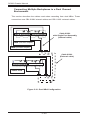
6-4 Cascading Backplanes
The SC836 chassis supports cascading when coupled with a SAS-836EL series
backplane or other Supermicro backplane with expander capabilities.
Power Control Card
In a cascaded configuration, backplanes can be linked to create "Just a Bunch of
Drives" or JBOD. The primary server requires a host bus adapter (or motherboard).
The other servers require a control card or power card.
6-4
Chapter 7: Rack Installation
Chapter 7
Rack Installation
7-1 Overview
This chapter provides a quick setup checklist to get your chassis up and running.
Following these steps in the order given should enable you to have the system
operational within a minimal amount of time.
7-2 Unpacking the System
You should inspect the box which the chassis was shipped in and note if it was
damaged in any way. If the chassis itself shows damage, you should file a damage
claim with the carrier who delivered it.
Decide on a suitable location for the rack unit that will hold your chassis. It should
be situated in a clean, dust-free area that is well ventilated. Avoid areas where
heat, electrical noise and electromagnetic fields are generated. The system needs
to be placed near a grounded power outlet. Be sure to read the Rack and Server
Precautions in the next section.
7-3 Preparing for Setup
The box your chassis was shipped in should include two sets of rail assemblies and
the mounting screws needed for installing the system into the rack. Also included
is an optional square hole to round hole converter bracket, for use in racks with
round mounting holes. Please read this section in its entirety before you begin the
installation procedure outlined in the sections that follow.
Choosing a Setup Location
•Leave enough clearance in front of the rack to enable you to open the front
door completely (~25 inches).
•Leave approximately 30 inches of clearance in the back of the rack to allow for
sufficient airflow and ease in servicing.
•This product is for installation only in a Restricted Access Location (dedicated
equipment rooms, service closets and the like).
7-1
SC836 Chassis Manual
!
Warning!
!
7-4 Warnings and Precautions
Rack Precautions
•Ensure that the leveling jacks on the bottom of the rack are fully extended to
the floor with the full weight of the rack resting on them.
•In single rack installations, stabilizers should be attached to the rack.
•In multiple rack installations, the racks should be coupled together.
•Always make sure that the rack is stable before extending a component from
the rack.
•You should extend only one component at a time - extending two or more simultaneously may cause the rack to become unstable.
General Server Precautions
•Review the electrical and general safety precautions that came with the components you are adding to your chassis.
•Determine the placement of each component in the rack before you install the
rails.
•Install the heaviest server components on the bottom of the rack first, and then
work upwards.
•Use a regulating uninterruptible power supply (UPS) to protect the server from
power surges, voltage spikes and to keep your system operating in case of a
power failure.
•Allow the hot plug hard drives and power supply modules to cool before touching them.
7-2
Chapter 7: Rack Installation
•Always keep the rack's front door and all panels and components on the servers
closed when not servicing to maintain proper cooling.
7-5 Rack Mounting Considerations
Ambient Operating Temperature
If installed in a closed or multi-unit rack assembly, the ambient operating temperature of the rack environment may be greater than the ambient temperature of the
room. Therefore, consideration should be given to installing the equipment in an
environment compatible with the manufacturer’s maximum rated ambient temperature (TMRA).
Reduced Airflow
Equipment should be mounted into a rack so that the amount of airflow required
for safe operation is not compromised.
Mechanical Loading
Equipment should be mounted into a rack so that a hazardous condition does not
arise due to uneven mechanical loading.
Circuit Overloading
Consideration should be given to the connection of the equipment to the power
supply circuitry and the effect that any possible overloading of circuits might have
on overcurrent protection and power supply wiring. Appropriate consideration of
equipment nameplate ratings should be used when addressing this concern.
Reliable Ground
A reliable ground must be maintained at all times. To ensure this, the rack itself
should be grounded. Particular attention should be given to power supply connections other than the direct connections to the branch circuit (i.e. the use of power
strips, etc.).
7-3
SC836 Chassis Manual
7-6 Rack Mounting Instructions
This section provides information on installing the chassis into a rack unit with the
rails provided. There are a variety of rack units on the market, which may mean
that the assembly procedure will differ slightly from the instructions provided. You
should also refer to the installation instructions that came with the rack unit you are
using. NOTE: This rail will fit a rack between 26.5" and 36.4" deep.
Identifying the Sections of the Rack Rails
The chassis package includes two rail assemblies in the rack mounting kit. Each
assembly consists of three sections: An inner chassis rail which secures directly to
the chassis, an outer rail that secures to the rack, and a middle rail which extends
from the outer rail. These assemblies are specifically designed for the left and right
side of the chassis.
Rail Assembly
(Shown with Rails
Retracted)
Outer Rail
Middle Rail
Locking Tab
This Side Faces
Outward
Inner Rail
Figure 7-1: Identifying the Outer Rail, Middle Rail and Inner Rails
(Left Rail Assembly Shown)
7-4
Chapter 7: Rack Installation
Locking Tabs
Each inner rail has a locking tab. This tab locks the chassis into place when installed
and pushed fully into the rack. These tabs also lock the chassis in place when fully
extended from the rack. This prevents the server from coming completely out of
the rack when when the chassis is pulled out for servicing.
Releasing the Inner Rail
Releasing Inner Rail from the Outer Rails
1. Identify the left and right outer rail assemblies as described on page 5-4.
2. Pull the inner rail out of the outer rail until it is fully extended as illustrated
below.
3. Press the locking tab down to release the inner rail.
4. Repeat steps 1-3 for the second outer rail.
1
12
13
14
Figure 7-2: Extending and Releasing the Inner Rail
7-5
SC836 Chassis Manual
Inner Rails
14
2
14
3
Figure 7-3: Installing the Inner Rails
Figure 7-4: Inner Rails Installed on the Chassis
(The chassis above are an example only. Actual chassis may differ slightly)
Installing The Inner Rails on the Chassis
Installing the Inner Rails
1. Confirm that the left and right inner rails have been correctly identified.
2. Place the inner rail firmly against the side of the chassis, aligning the hooks
on the side of the chassis with the holes in the inner rail.
3. Slide the inner rail forward toward the front of the chassis until the rail clicks
into the locked position, which secures the inner rail to the chassis.
4. Secure the inner rail to the chassis with the screws provided.
5. Repeat steps 1 through 4 above for the other inner rail.
7-6
Chapter 7: Rack Installation
1
L-min=676.00(26.61")(outer rail)
12
14
21D01
13
Figure 7-5: Extending and Releasing the Outer Rails
Installing the Outer Rails on the Rack
Installing the Outer Rails
1. Press upward on the locking tab at the rear end of the middle rail.
2. Push the middle rail back into the outer rail.
3. Hang the hooks of the front of the outer rail onto the slots on the front of
the rack. If necessary, use screws to secure the outer rails to the rack, as
illustrated above.
4. Pull out the rear of the outer rail, adjusting the length until it fits within the
posts of the rack.
5. Hang the hooks of the rear portion of the outer rail onto the slots on the rear
of the rack. If necessary, use screws to secure the rear of the outer rail to the
rear of the rack.
6. Repeat steps 1-5 for the remaining outer rail.
7-7
SC836 Chassis Manual
Ball-Bearing
Shuttle
Figure 7-6: Installing into a Rack
Standard Chassis Installation
Installing the Chassis into a Rack
1. Confirm that the inner rails are properly installed on the chassis.
2. Confirm that the outer rails are correctly installed on the rack.
3. Pull the middle rail out from the front of the outer rail and make sure that the
ball-bearing shuttle is at the front locking position of the middle rail.
4. Align the chassis inner rails with the front of the middle rails.
5. Slide the inner rails on the chassis into the middle rails, keeping the pressure
even on both sides, until the locking tab of the inner rail clicks into the front of
the middle rail, locking the chassis into the fully extended position.
6. Depress the locking tabs of both sides at the same time and push the chassis
all the way into the rear of the rack.
7. If necessary for security purposes, use screws to secure the chassis handles
to the front of the rack.
7-8
Chapter 7: Rack Installation
Optional Quick Installation Method
The following quick installation method may be used to install the chassis onto a
rack.
Installing the Chassis into a Rack
1. Install the whole rail assembly onto the rack as described on page 7-7.
2. Release the inner rail without retracting the middle rail.
3. Install the inner rails on the chassis as previously described on page 7-6.
4. Install the chassis onto the middle rail as described in the previous section.
7-9
SC836 Chassis Manual
Notes
7-10
Appendix A: Chassis Cables
Appendix A
SC836 Chassis Cables
A-1 Overview
This appendix lists supported cables for your chassis system. It only includes the
most commonly used components and configurations. For more compatible cables,
refer to the manufacturer of the motherboard you are using and our Web site at:
www.supermicro.com.
A-2 Cables Included with SC836 Chassis (SAS/SATA)
SC836TQ-800
Part #
Type
Length
CBL-0087
Ribbon,
Round
20"
CBL-0179L
Cable
70mm
Cable
6'
CBL-0180L-01
SATA
various
CBL-0139L
Wire
45cm
Part #
Type
Length
CBL-033L-U320
Cable
9'
CBL-0063L
Cable
20"
CBL-0139L
Wire
45cm
CBL-0160L
Cord
---
-
Description
16 pin to 16 pin ribbon cable for
control panel
SATA cable
Regional power cord
Set for 4 SATA cables. length varied
to minimize airflow interference.
IDE 80-wire cable for DVD-ROM
SC836S-800
Description
9" 2-drop U320 SCSI cable
20"SCSI cable
IDE 80-wire cable for DVD-ROM
Power cord
A-1
SC836 Chassis Manual
SC836E-800
Part #
Type
Length
CBL-0087
Ribbon,
Round
20"
CBL-0179L
Cable
70mm
Cable
6'
CBL-0139L
Wire
45cm
Part #
Type
Length
Ribbon,
Round
20"
-
Description
16 pin to 16 pin ribbon cable for
control panel
SATA cable
Regional power cord
IDE 80-wire cable for DVD-ROM
SC836A-1200
CBL-0087
A-2
Description
16 pin to 16 pin ribbon cable for
control panel
Appendix A: Chassis Cables
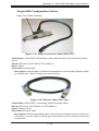
A-4 Compatible Cables
This section lists cables included with the SC836 chassis packages
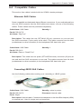
Alternate SAS Cables
Some compatible motherboards have different connectors. If your motherboard has
only one SAS connector that the SAS cables must share, use one of the following
cables. These cables must be purchased separately.
Cable Name: SAS Cable
Quantity: 1
Part #: CBL-0175L
Alt. Name: "Big Four"
Description: This cable has one SFF-8484 (32 pin) connector on one end and
four SAS connectors (7 pins each) at the other. This cable connects from the host
(motherboard or other controller) to the backplane SAS hard drive port.
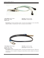
Cable Name: SAS Cable
Quantity: 1
Part #: CBL-0116
Alt. Name: iPass or "Small Four"
Description: This cable has one ipass (SFF-8087/mini-sas) connector (36 pins) at
one end and four SAS connectors on one end. This cable connects from the host
(motherboard or other controller) to the backplane SAS hard drive port.
Cascading/JBOD SAS Cables
Use the following cables when setting up a cascading or JBOD system.
Cable Name: SAS Cable
Quantity: varies by setup
Part #: CBL-0167L
Ports: Single
Placement: Internal cable
Description: Internal cable. Connects the backplane to the Host Bus Adapter (HBA)
or external port. Used in single port environments.
A-3
SC836 Chassis Manual
Cable Name: SAS Cable
Quantity: varies by setup
Part #: CBL-0168L
Ports: Dual
Placement: Internal cable
Description: Internal cascading cable. Connects the backplane to the Host Bus
Adapter (HBA) or external port. Used in dual port environments.
Cable Name: SAS Cable
Quantity: varies by setup
Part #: CBL-0166L
Placement: External cable
Ports: Single or Dual
Description: External cascading cable. Connects ports between servers. With most
connectors, use one cable for single port connections and two cables for dual port
connections.
A-4
Appendix A: Chassis Cables
Extending Power Cables
Although Super Micro chassis are designed with to be efficient and cost-effective,
some compatible motherboards have power connectors located in different areas.
To use these motherboards you may have to extend the power cables to the mother
boards. To do this, use the following chart as a guide.
Power Cable Extenders
Number of Pins
Cable Part #
Length
24 pin
CBL - 0042
7.9”(20 CM)
20 pin
CBL - 0059
7.9”(20 CM)
8 pin
CBL - 0062
7.9”(20 CM)
4 pin
CBL - 0060
7.9”(20 CM)
Front Panel to the Motherboard
The SC836 chassis includes a cable to connect the chassis front panel to the
motherboard. If your motherboard uses a different connector, use the following list
to find a compatible cable.
Front Panel to Motherboard Cable (Ribbon Cable)
Number of Pins
(Front Panel)
Number of Pins
(Motherboard)
Cable Part #
16 pin
16 pin
CBL - 0049
16 pin
20 pin
CBL - 0048
20 pin
20 pin
CBL - 0047
16 pin
various*
CBL - 0068
20 pin
various*
CBL - 0067
* Split cables: Use these cable if your motherboard requires several different connections from the front panel.
A-5
SC836 Chassis Manual
Notes
A-6
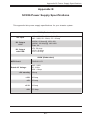
Appendix B: Power Supply Specifications
Appendix B
SC836 Power Supply Specifications
This appendix lists power supply specifications for your chassis system.
1200W (Redundant)
100 - 140V, 50 - 60Hz, 8 - 11.5 Amp
180 - 240V, 50 - 60Hz, 5.5 - 8 Amp
AC Input
DC Output
+12V
1000W, 83 Amp @ 100-140V
1200W, 100 Amp @ 180-240V
5Vsb: 4A
DC Output
with PDB
+5V: 50 Amp
+3.3V: 30 Amp
-12V: 0.6 Amp
800W (Redundant)
MFR Part #
PWS-801-1R
Rated AC Voltage
100 - 240V
50 - 60Hz
10A - 4 Amp
+5V standby 4 Amp
+12V
66 Amp
+5V
25 Amp
+3.3V
12 Amp
-12V
0.5 Amp
B-1
SC836 Chassis Manual
710W (Redundant)
MFR Part #
PWS-711-1R
Rated DC Input
Voltage
Voltage Range: -36 to -75V (24A-11A)
Nominal Voltage: -48V
+5V standby 4 Amp
+12V
58 Amp
+5V
24 Amp
+3.3V
21 Amp
-12V
0.6 Amp
B-2
Appendix C: SAS-836EL Backplane Specifications
Appendix C
SAS-836EL Backplane Specifications
To avoid personal injury and property damage, carefully follow all the safety steps listed
below when accessing your system or handling the components.
C-1 ESD Safety Guidelines
Electrostatic Discharge (ESD) can damage electronic components. To prevent damage to your system, it is important to handle it very carefully. The following measures
are generally sufficient to protect your equipment from ESD.
•Use a grounded wrist strap designed to prevent static discharge.
•Touch a grounded metal object before removing a component from the antistatic
bag.
•Handle the backplane by its edges only; do not touch its components, peripheral
chips, memory modules or gold contacts.
•When handling chips or modules, avoid touching their pins.
•Put the card and peripherals back into their antistatic bags when not in use.
C-2 General Safety Guidelines
•Always disconnect power cables before installing or removing any components
from the computer, including the backplane.
•Disconnect the power cable before installing or removing any cables from the
backplane.
•Make sure that the backplane is securely and properly installed on the motherboard to prevent damage to the system due to power shortage.
C-1
SC836 Chassis Manual
C-3 An Important Note to Users
•All images and layouts shown in this user's guide are based upon the latest PCB
Revision available at the time of publishing. The card you have received may or
may not look exactly the same as the graphics shown in this manual.
C-4 Introduction to the SAS-836EL Backplane
The SAS-836EL backplane has been designed to utilize the most up-to-date technology available, providing your system with reliable, high-quality performance.
This manual reflects SAS-836EL Revision 1.01 the most current release available at
the time of publication. Always refer to the Supermicro Web site at www.supermicro.
com for the latest updates, compatible parts and supported configurations.
C-2
Appendix C: SAS-836EL Backplane Specifications
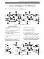
Jumper Settings and Pin Definitions
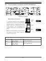
C-4 Front Connectors and Jumpers
1
12
1
2
1
PRI_J2
SEC_J2
PW R0
+12V
+12V
14
+5V
+12V
15
PW R2
GND
GND
13
13
1
+12V
17
FAN1
J17
16
SAS836EL
91
10
1
PRI_EXP
REV 1.01
16
A
C
12V_LED
5V_LED
FANFAIL1
A
11
111
12
1
PRI_FLASH
GND
GND
SEC_FLASH
GND
GND
CB154
PW R3
+5V
+5V
OVERHEATFAIL1
C A
C A
C
PRI_J0
PRI_M ODE5
GND
13
REM OTE_FAN_FAIL_SCOKET
FAN_ALERT_EN1
GND
PRI_J1
JP105
PRI_M ODE4
SEC_M ODE5
SEC_M ODE4
WWN
14
1
SEC_EXP
PW R1
+5V
SEC_J1
PRI_IPM I
SEC_IPM I
13
BUZZER1
SEC_J0
JP106
PRI_I2C
SEC_I2C
BUZZER_ENB1
J16
5
1
17
FAN3
FAN2
FAN4
18
8
1
18
18
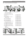
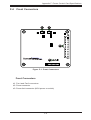
Figure C-1: SAS-836EL2 Backplane
Front Connectors
1. CD-ROM/Drive Power: JP105 and
JP106
2 and 3. Primary and Secondary I2C
Fan4 (Fan1 is not used)
9. SAS Connectors: PRI_J0
10. SAS Connectors: PRI_J1
connectors (optional)
11. SAS Connectors: PRI_J2
4. Power Connectors: PWR0, PWR1,
PWR2, and PWR3
12. SAS Connectors: SEC_J1 (not available in EL1 single port backplanes)
5. Primary and Secondary Expander
Chip
13. SAS Connectors: SEC_J0 (not available in EL1 single port backplanes)
6. Primary and Secondary Flash Chip
14. SAS Connectors: SEC_J2 (not available in EL1 single port backplanes)
7. EPP Connectors: J16 and J17
8. Fan Connectors: Fan2, Fan3, and
1
1
12
PRI_J2
GND
PW R0
+12V
GND
GND
+12V
14
GND
GND
+12V
SAS836EL
PRI_EXP
PW R2
+5V
GND
GND
+12V
FAN1
16
C A
C A
C
PRI_J0
10
1
J16
15
REV 1.01
PRI_FLASH
PW R3
+5V
+5V
19
A
12V_LED
5V_LED
FANFAIL1
C
PRI_M ODE5
11
111
FAN_ALERT_EN1
GND
A
REM OTE_FAN_FAIL_SCOKET
WWN
PW R1
+5V
OVERHEATFAIL1
JP105
PRI_M ODE4
BUZZER1
PRI_J1
PRI_IPM I
13
JP106
PRI_I2C
BUZZER_ENB1
7
1
FAN3
FAN2
FAN4
18
18
8
1
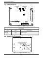
Figure C-2: SAS-836EL1 Backplane
C-3
81
SC836 Chassis Manual
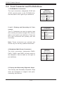
C-5 Front Connector and Pin Definitions
1. CD-ROM4-Pin Connectors
The 4-pin connectors, designated JP105 and
JP106, provide power to the CD-ROM drive.
See the table on the right for pin definitions.
CD-ROM/
FDD Power
4-Pin Connector
(JP105 and JP106)
Pin# Definition
1
+5V
2 and 3
Ground
4
2 and 3. Primary and Secondary I2C Connectors
The I2C Connectors are used to monitor hard
drive activity and status through LED. See the
table on the right for pin definitions. There are
four total connectors--two primary and two
secondary.
+12V
I2C Connector
Pin Definitions
Pin# Definition
1
Data
2
Ground
3
Clock
4
No Connection
Note: These connectors are optional and
should only be used by qualified technicians.
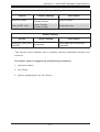
4. Backplane Main Power Connectors
The 4-pin connectors, designated PWR0,
PWR1, PWR2, and PWR3, provide power to
the backplane. See the table on the right for
pin definitions.
Backplane
Main Power
4-Pin Connector
Pin# Definition
1
2 and 3
4
5. Primary and Secondary Expander Chips
This Primary and Secondary Expander Chips
allow the backplane to support dual ports,
cascading, and failover.
C-4
+12V
Ground
+5V
Appendix C: SAS-836EL Backplane Specifications
6. Primary and Secondary Flash Chips
The Primary and Secondary Flash Chips enhance the backplane memory.
7. EPP Ports
The EPP ports are used for manufacturer
diagnostic purposes only.
8. Fan Connectors
Fan Connectors
The 3-pin connectors, designated Fan2, Fan3,
and Fan4, provide power to the fans.
A fan may be connected to Fan1; however,
connector Fan1 is not fully supported by the
backplane. Any fan connected to Fan1 will not
be monitored.
See the table on the right for pin definitions.
9-14. SAS Ports
This backplane supports SAS drives only.
Note that the Primary and Secondary sets of
SAS ports are in different order. From right to
left the ports are Primary 0, 1, 2 and Secondary 1, 0, 2.
C-5
Pin# Definition
1
Ground
2
+12V
3
Tachometer
SC836 Chassis Manual
C-6 Front Jumper Locations and Pin Definitions
PRI_J2
SEC_J2
JP106
SEC_J0
SEC_J1
PRI_J1
OVERHEATFAIL1
PRI_I2C
SEC_I2C
BUZZER_ENB1
A
A
12V_LED
5V_LED
FANFAIL1
C
C A
C A
C
SEC_M ODE5
SEC_M ODE4
WWN
PRI_M ODE5
BUZZER1
REM OTE_FAN_FAIL_SCOKET
PRI_M ODE4
SEC_IPM I
PRI_IPM I
PRI_J0
JP105
FAN_ALERT_EN1
SEC_EXP
PW R1
+5V
GND
GND
PW R0
+12V
+5V
GND
GND
J16
PRI_EXP
+12V
SAS836EL
REV 1.01
PW R2
+12V
+5V
GND
GND
+12V
FAN1
PRI_FLASH
GND
SEC_FLASH
GND
CB154
PW R3
+5V
PRI_J1
SEC_J2
FAN3
FAN2
J17
OVERHEATFAIL1
SEC_I2C
BUZZER_ENB1
A
+5V
GND
GND
+12V
SAS836EL
Figure C-3: Backplane Jumper Settings
GND
GND
+12V
Connector
Pins
FAN1
To modify the operation of the backplane,
jumpers can be used to choose between
optional settings. Jumpers create shorts
between two pins to change the function
of the connector. Pin 1 is identified with
a square solder pad on the printed circuit
board. Note: On two pin jumpers, "Closed"
means the jumper is on and "Open" means
the jumper is off the pins.
FAN4
Setting
Note
PRI_MODE4
1-2
Factory setting
Do not change
PRI_MODE5
2-3
Factory setting
Do not change
SEC_MODE4
1-2
Factory setting
Do not change
SEC_MODE5
2-3
Factory setting
Do not change
C-6
1
3
2
1
Jumper
General Jumper Settings
Jumper Settings
2
FAN2
J17
Jumper
3
PRI_FLASH
+5V
SEC_FLASH
PW R2
+12V
CB154
GND
REV 1.01
J16
Explanation of Jumpers
PW R3
GND
REM OTE_FAN_FAIL_SCOKET
Remote Fan
Fail
Fan Alert Enable
PW R0
+12V
PRI_EXP
+5V
PRI_M ODE5
GND
SEC_J1
PRI_Mode4
PRI_Mode5
SEC_Mode5
FAN_ALERT_EN1
PW R1
FAN4
SEC_J0
CJP106
PRI_M ODE4
SEC_IPM I
SEC_M ODE5
SEC_M ODE4
WWN
SEC_Mode4
GND
C A
BUZZER1
SEC_EXP
+5V
C A
PRI_J0
Buzzer Enable
JP105
A
12V_LED
5V_LED
FANFAIL1
C
Appendix C: SAS-836EL Backplane Specifications
General Jumper Settings
Jumper
Jumper Settings
Description
BUZZER_ENB1
Open: Disable
Closed: Enable
Buzzer enable*
FAN_ALERT_ENI
Open: Disable
Closed: Enable
Enable fan alert
Socket Settings
Socket
REMOTE_FAN_FAIL_
SOCKET
Socket Setting
Description
Front panel fan fail indicator
(Optional)
Connected
*The buzzer sound indicates that a condition requiring immediate attention has
occurred.
The buzzer alarm is triggered by the following conditions:
1. Hard drive failure
2. Fan failure
3. System temperature over 45º Celsius.
C-7
SC836 Chassis Manual
Front LED Indicators
PRI_J2
SEC_J2
JP106
SEC_J0
SEC_J1
PRI_J1
OVERHEATFAIL1
PRI_I2C
SEC_I2C
BUZZER_ENB1
A
A
12V_LED
5V_LED
FANFAIL1
C
C A
C A
C
PRI_M ODE5
SEC_M ODE5
SEC_M ODE4
WWN
REM OTE_FAN_FAIL_SCOKET
PRI_M ODE4
SEC_IPM I
PRI_IPM I
PRI_J0
JP105
BUZZER1
FAN_ALERT_EN1
SEC_EXP
PW R1
+5V
GND
GND
PW R0
+12V
+5V
GND
GND
J16
PRI_EXP
+12V
SAS836EL
REV 1.01
PW R2
+12V
+5V
GND
GND
+12V
PRI_FLASH
GND
SEC_FLASH
GND
CB154
PW R3
+5V
FAN1
FAN3
FAN2
J17
FAN4
OVERHEATFAIL1
Overheat/
Fan Fail LEDs
A
A
C A
Fan Failure
LED
PRI_J0
12V_LED
5V_LED
FANFAIL1
C
C A
C
Power Failure
LEDs
PRI_M ODE4
Figure C-4: Backplane LED Indicators
PRI_M ODE5
Backplane LEDs
LED
State
Specification
OVERHEATFAIL1
On
Overheat or drive failure
FANFAIL1
On
Failure in system fans
5V
Off
Backplane power failure. Light is on
during normal operation.
12V
Off
Backplane power failure. Light is on
during normal operation.
J16
C-8
Appendix C: SAS-836EL Backplane Specifications
C-7 Rear Connectors and LED Indicators
C
A
SAS HDD #5
SAS #13
SAS HDD #13
SAS #6
SAS HDD #6
SAS #14
SAS HDD #14
SAS #7
SAS HDD #7
SAS #15
SAS HDD #15
Rear LED Indicators
Rear LED
Hard Drive Activity
Failure LED
SAS #0
ACT #0
FAIL #0
SAS #1
ACT #1
FAIL #1
SAS #2
ACT #2
FAIL #2
SAS #3
ACT #3
FAIL #3
SAS #4
ACT #4
FAIL #4
SAS #5
ACT #5
FAIL #5
SAS #6
ACT #6
FAIL #6
SAS #7
ACT #7
FAIL #7
SAS #8
ACT #8
FAIL #8
SAS #9
ACT #9
FAIL #9
SAS #10
ACT #10
FAIL #10
C-9
C86
A FAIL12
SAS #5
C
SAS HDD #12
A
J12
C
SAS HDD #11
SAS #12
ACT12
SAS
#12
FAIL#12
ACT#12
FAIL#12
ACT#12
SAS #11
SAS HDD #4
FAIL#13
SAS HDD #3
SAS #4
A FAIL13
SAS #3
C
SAS HDD #10
C
FAIL#8
FAIL8
SAS HDD #9
SAS #10
ACT13
C
ACT8
ACT#8
SAS #9
SAS HDD #2
ACT#13
A
SAS HDD #1
SAS #2
FAIL14
FAIL9
FAIL#9
SAS #1
FAIL#14
C
FAIL4
FAIL#4
SAS HDD #8
A
A
A
SAS #8
A
J13
SAS
#13
SAS Drive
Number
SAS HDD #0
A
C
C
ACT9
SAS #13
J13
SAS #0
C
SAS
ACT#9
C
Rear
Connector
ACT14
J14
ACT#13
FAIL#13
#14
Rear SAS Connectors
SAS Drive
Number
ACT#14
ACT#14
FAIL#14
Figure C-5: Rear Connectors and LED Indicators
Rear
Connector
FAIL15
A
SAS #14
J14
SAS #12
J12
FAIL#15
FAIL10
FAIL#10
A
A
C
SEC_SRAM 1
PRI_SRAM 1
C A
ACT#8
FAIL#8
C
A
SEC_SRAM 2
PRI_SRAM 2
ACT4
ACT#4
A
J8
C
C
A
FAIL0
FAIL#0
SAS
#8
A
J15
SAS
#15
ACT#10
ACT10
C
J9
ACT15
FAIL#11
A FAIL11
A
FAIL5
FAIL#5
SAS
#9
ACT#9
FAIL#9
SAS #15
J15
ACT#15
C
C
ACT5
C
SAS #8
J8
A
J10
SAS
#10
ACT#5
ACT0
ACT#0
SAS #9
J9
C
A
C
ACT#4
FAIL#4
J4
SAS
#4
SAS #10
J10
ACT#15
FAIL#15
ACT#11
C
FAIL6
J5
FAIL#6
A
SAS #4
J4
C
FAIL1
FAIL#1
SAS
#5
ACT#5
FAIL#5
ACT#10
FAIL#10
#11
ACT6
J6
C
ACT#0
FAIL#0
ACT#6
FAIL#6
SAS
#6
J11
SAS
ACT#6
A
J0
A
C
#0
FAIL7
ACT1
ACT#1
SAS
SAS #5
J5
FAIL#7
A
#1
C
FAIL2
FAIL#2
J1
SAS
A
C
ACT#1
FAIL#1
SAS #6
J6
ACT7
ACT2
ACT#2
C
#2
#7
A
J2
SAS
SAS #11
J11
J7
SAS
ACT#11
FAIL#11
ACT#7
A
ACT#2
FAIL#2
#3
SAS #7
J7
C
FAIL3
FAIL#3
A
C
SAS #0
J0
J3
SAS
ACT#7
FAIL#7
ACT3
SAS #1
J1
C
SAS #2
J2
ACT#3
FAIL#3
ACT#3
SAS #3
J3
SC836 Chassis Manual
Rear LED Indicators
SAS #11
ACT #11
FAIL #11
SAS #12
ACT #12
FAIL #12
SAS #13
ACT #13
FAIL #13
SAS #14
ACT #14
FAIL #14
SAS #15
ACT #15
FAIL #15
C-10
Appendix C: SAS-836EL Backplane Specifications
Dual Port and Cascading Configurations
C-8 Single and Dual Port Expanders
Single Ports
SAS-836EL1 backplanes have a single-port expander that access all sixteen drives
and supports cascading.
Dual Ports
SAS-836EL2 backplanes have dual-port expanders that access all sixteen drives.
These dual-port expanders support cascading, failover, and recovery.
From HBA or higher
From HBA or higher
backplane
backplane
Port B
Secondary Ports
Expander 2
Port A
Primary Ports
Expander 1
PRI_J2
SEC_J2
SEC_J0
J2
SEC_J1
J0
PRI_J1
J1
J1 J2
To lower backplane in
cascaded system
PRI_J0
J0
To lower backplane in
cascaded system
Figure C-6: SAS-836EL2 Dual Port Configuration
From HBA or higher
backplane
Port A
Primary Ports
PRI_J2
SEC_J2
SEC_J0
SEC_J1
PRI_J1
J2
J1
To lower backplane in
cascaded system
Figure C-7: SAS-836EL1 Single Port Configuration
C-11
PRI_J0
J0
SC836 Chassis Manual
C-9 Failover
The SAS-836EL2 backplane has two expanders which allow effective failover and
recovery.
Single Host Bus Adapter
SAS HBA
PRI_J2
SEC_J2
SEC_J0
PRI_J1
SEC_J1
PRI_J0
WWN
In a single host bus configuration, the
backplane connects to one Host Bus
Adapter (HBA).
Port B
Expander 2
Port A
Expander 1
J17
Figure C-8: Single HBA
Single Host Bus Adapter
Failover
SAS HBA
PRI_J2
SEC_J2
SEC_J0
PRI_J1
SEC_J1
PRI_J0
WWN
If the expander or data path in Port A
fails, the system automatically switches
to Port B.
Port B
Expander 2
Port A
Expander 1
J17
Figure C-9: Single HBA Failover
Dual Host Bus Adapter
SAS HBA
In a dual host bus configuration, the
backplane connects to two Host Bus
Adapters (HBA).
SAS HBA
PRI_J2
SEC_J2
SEC_J0
PRI_J1
SEC_J1
PRI_J0
WWN
Port B
Expander 2
Port A
Expander 1
J17
Figure C-10: Dual HBA
SAS HBA
Dual Host Bus Adapter
Failover
SAS HBA
PRI_J2
SEC_J2
SEC_J0
PRI_J1
SEC_J1
PRI_J0
WWN
If the expander or data path in Port A
fails, the system automatically switches
to Port B. This maintains a full connection to all drives.
Port B
Expander 2
Port A
Expander 1
J17
Figure C-11: Dual HBA Failover
C-12
Appendix C: SAS-836EL Backplane Specifications
C-10 Cables and Chassis Power Card
Chassis Power Card
In a cascaded configuration, the first chassis includes a motherboard and at least
one Host Bus Adapter (HBA). Other servers in this enclosed system, include a
power card. This section describes the supported power card for the SAS-836
series backplane.
For more information, see the PCC-JBPWR2 power card manual. This manual a
can be found at the http://www.supermicro.com or as an appendix in the SAS-836EL
chassis manual.
A
A
A
JBPWR2 REV 1.00
Figure C-12: Chassis Power Card (Sold Separately)
Power Card
Part Number
CSE-PTJBOD-CB1
Part Type
Power Card
C-13
Where Used
Allows the chassis to be in a
JBOD (Just a Bunch of Drives)
system.
SC836 Chassis Manual
Connecting an Internal Host Bus Adapter to the
Backplane
The following section lists the most common cables used to connect the HBA to
the backplane.
PRI_J2
SEC_J2
SEC_J0
PRI_J1
SEC_J1
PRI_J0
WWN
J17
HBA
(Host Bus Adapter)
Figure C-13: Single Internal Host Bus Adapter
PRI_J2
SEC_J2
SEC_J0
PRI_J1
SEC_J1
PRI_J0
WWN
J17
HBA
HBA
(Host Bus Adapter)
(Host Bus Adapter)
Figure C-14: Dual Internal Host Bus Adapter
Supported Internal HBA to Backplane Cables
Use the following listed cables to create connections between the internal HBA and
SAS-836EL backplane. The cables required depend on the HBA connector.
Cable Name: iPass TO 4-LANE
Part #: CBL-0117
Length: 46 cm (18 inches)
Description: This cable has one SFF-8484 (32 pin) connector on one end and
iPass (SFF-8087/Mini-SAS) connector (36 pins) at the other. This cable connects
from the HBA to the SAS-836EL backplane.
C-14
Appendix C: SAS-836EL Backplane Specifications
Cable Name: iPass (Mini-SAS) TO iPass (Mini-SAS)
Part #: CBL-0108L-02
Length: 39 cm (15 inches)
Part #: CBL-0109L-02
Length: 22 cm (9 inches)
Part #: CBL-0110L-02
Length: 18 cm (7 inches)
Description: This cable has an iPass (SFF-8087/Mini-SAS) connector (36 pins) at
each end. It connects from the HBA to the SAS-836EL backplane.
C-15
SC836 Chassis Manual
Connecting an External Host Bus Adapter to the
Backplane
This backplane supports external Host Bus Adapters. In this configuration, the HBA
and the backplane are in different physical chassis. This allows a JBOD (Just a
Bunch Of Drives) configuration from an existing system.
PRI_J2
SEC_J2
SEC_J0
PRI_J1
SEC_J1
PRI_J0
WWN
J17
HBA
Power Card
(Host Bus Adapter)
CBL-0200L
External HBA Cable
Figure C-15: Single External Host Adapter
PRI_J2
SEC_J2
SEC_J0
PRI_J1
SEC_J1
PRI_J0
WWN
HBA
(Host Bus Adapter)
J17
HBA
Power Card
(Host Bus Adapter)
Dual External Host Bus Adapter
CBL-0200L
External HBA Cables
Figure C-16: Dual External Host Bus Adapter
C-16
Appendix C: SAS-836EL Backplane Specifications
Supported External HBA to Backplane Cable
Use the following cable if your external HBA has an InfiniBand connector.
Figure C-17: SAS InfiniBand Cable (CBL-0200L)
Cable Name: SAS InfiniBand to Mini-SAS X4 1M cable, PBF
Part #: CBL-0200L
Length: 1 meter
Description: This cable has an InfiniBand connector (SFF-8470) on one end and
an SFF-8088-1X (26-pins) at the other end.
C-17
SC836 Chassis Manual
Connecting Multiple Backplanes in a Single Channel
Environment
This section describes the cables used when cascading from a single HBA. These
connections use CBL-0167L internal cables and CBL-0166L external cables.
PRI_J2
SEC_J2
SEC_J0
CBL-0167L
with Single Port Assembly
(Internal cable)
PRI_J1
SEC_J1
PRI_J0
WWN
Port B Expander 2 Port A Expander
J17
HBA (Host Bus Adapter)
CBL-0166L
(External cable)
PRI_J2
SEC_J2
SEC_J0
PRI_J1
SEC_J1
PRI_J0
WWN
Port B Expander 2
Port A Expander 1
J17
Power Card
Figure C-18: Single HBA Configuration
C-18
Appendix C: SAS-836EL Backplane Specifications
Single HBA Configuration Cables
Single Port Cable Assembly
Figure C-19: Single Port Internal Cable (CBL-167L)
Cable Name: SAS EL2/EL1 Backplane Cable (Internal) with 2-port Cascading Cable,
68 cm
Part #: CBL-0167L (SFF-8087 to SFF-8088 x1)
Ports: Single
Placement: Internal cable
Description: Internal cable. Connects the backplane to the Host Bus Adapter (HBA)
or external port. Used in single port environments.
Figure C-20: External Cable (CBL-166L)
Cable Name: SAS EL2/EL1 Cascading Cable (External), 68cm
Part #: CBL-0166L (SFF-8088 1x to SFF-8088 x1)
Ports: Single or Dual
Placement: External cable
Description: External cascading cable. Connects ports between servers. With most
connectors, use one cable for single port connections and two cables for dual port
connections.
C-19
SC836 Chassis Manual
Connecting Multiple Backplanes in a Dual Channel
Environment
This section describes the cables used when cascading from dual HBAs. These
connections use CBL-0168L internal cables and CBL-0166L external cables.
PRI_J2
SEC_J2
SEC_J0
PRI_J1
SEC_J1
PRI_J0
WWN
Port B Expander Port A Expander
J17
Cable 0168L
with Single Port Assembly
(Internal cable)
HBA (Host Bus Adapter)
HBA (Host Bus Adapter)
Cable 0166L
(External cable)
PRI_J2
SEC_J2
SEC_J0
PRI_J1
SEC_J1
PRI_J0
WWN
Port B Expander
Port A Expander 1
J17
Power Card
Figure C-21: Dual HBA Configuration
C-20
Appendix C: SAS-836EL Backplane Specifications
Dual HBA Configuration Cables
Dual Port Cable
Assembly
Figure C-22: Dual Port Internal Cable (CBL-168L)
Cable Name: SAS Dual-port Cable Assembly, 68/76cm
Part #: CBL-0168L
Ports: Dual
Placement: Internal cable
Description: Internal cascading cable. Connects the backplane to the Host Bus
Adapter (HBA) or external port. Used in dual port environments.
Figure C-23: External Cable (CBL-166L)
Cable Name: SAS EL2/EL1 Cascading Cable (External), 68cm
Part #: CBL-0166L
Placement: External cable
Ports: Single or dual
Description: External cascading cable. Connects ports between servers. Use one
cable for single port connections and two cables for dual port connections.
C-21
SC836 Chassis Manual
C-11 Supported Cascading Configurations
Cascading allows the system to access data at a faster rate by allowing several
backplanes to share resources to reduce latency time.
The first backplane in a cascaded system requires a motherboard and HBA. Other
servers require a power control card with no motherboard and no HBA. For more
information, see the SC836 Chassis Manual available at www.supermicro.com.
PRI_J2
SEC_J2
SEC_J0
PRI_J1
SEC_J1
PRI_J0
WWN
Port B Expander 2 Port A Expander
J17
Single Port Cable
Assembly
HBA (Host Bus Adapter)
Cable 0167L
(internal cable)
PRI_J2
SEC_J2
SEC_J0
Cable 0166L
(External cable)
PRI_J1
SEC_J1
PRI_J0
WWN
Port B Expander
Port A Expander 1
J17
Power Card
PRI_J2
SEC_J2
SEC_J0
PRI_J1
SEC_J1
PRI_J0
WWN
Port B Expander Port A Expander
J17
Power Card
Figure C-24: Simple Cascaded Configuration
C-22
Appendix C: SAS-836EL Backplane Specifications
Server System with Single SAS HBA
The expanders allow horizontal branching. This configuration also applies to dual
ports.
PRI_J2
SEC_J2
SEC_J0
PRI_J2
SEC_J2
PRI_J1
SEC_J0
SEC_J1
PRI_J1
SEC_J1
PRI_J0
PRI_J0
WWN
WWN
Port A Expander 1
J17
Port A Expander 1
J17
Power Card
HBA
Cable 0167L
(internal cable)
Single Port Cable
Assembly
PRI_J2
SEC_J2
SEC_J0
PRI_J1
PRI_J2
SEC_J2
SEC_J1
SEC_J0
PRI_J1
SEC_J1
PRI_J0
PRI_J0
WWN
WWN
Port A Expander 1
J17
Port A Expander 1
J17
Power Card
Power Card
Cable 0166L
(external cable)
PRI_J2
SEC_J2
SEC_J0
PRI_J1
PRI_J2
SEC_J2
SEC_J1
SEC_J0
PRI_J1
SEC_J1
PRI_J0
PRI_J0
WWN
WWN
J17
Port A Expander
J17
Power Card
Port A Expander
Power Card
Figure C-25: Cascaded Configuration with Horizontal Branching
C-23
SC836 Chassis Manual
Dual SAS HBA and Cascaded Configuration
PRI_J2
SEC_J2
SEC_J0
PRI_J1
SEC_J1
PRI_J0
WWN
Port A Ex. 1
Port B Ex. 2
J17
HBA
Dual Port Cable
Assembly
HBA
Cable 0168L
(Internal cable)
PRI_J2
SEC_J2
SEC_J0
Cable 0166L
(External cables)
PRI_J1
SEC_J1
PRI_J0
WWN
Port B Expander 2
Port A Expander 1
J17
Power Card
PRI_J2
SEC_J2
SEC_J0
PRI_J1
SEC_J1
PRI_J0
WWN
Port B Expander 2
Port A Expander 1
J17
Power Card
Figure C-26: Dual SAS HBA with Cascaded Configuration
C-24
Appendix C: SAS-836EL Backplane Specifications
Dual SAS HBA with Cascaded Configuration and Branching
PRI_J2
SEC_J2
SEC_J0
PRI_J1
SEC_J1
PRI_J0
WWN
Port B Ex. 2
Port A Ex. 1
J17
PRI_J2
SEC_J2
SEC_J0
PRI_J1
SEC_J1
PRI_J0
WWN
Port B Ex. 2
Port A Ex. 1
J17
Power
Card
HBA
HBA
PRI_J2
SEC_J2
SEC_J0
PRI_J1
SEC_J1
PRI_J0
WWN
Port B Ex. 2 Port A Ex. 1
J17
PRI_J2
SEC_J2
SEC_J0
PRI_J1
SEC_J1
PRI_J0
WWN
Port B Ex. 2
Port A Ex. 1
J17
Power
Card
Power
Card
Cable 0166L
(External cable)
PRI_J2
SEC_J2
SEC_J0
PRI_J1
SEC_J1
PRI_J0
WWN
Port B Ex. 2 Port A Ex. 1
J17
PRI_J2
SEC_J2
SEC_J0
PRI_J1
SEC_J1
PRI_J0
WWN
Port B Ex. 2
J17
Port A Ex. 1
Power
Card
Power
Card
Figure C-27: Dual SAS HBA with Cascaded Configuration and Branching
C-25
SC836 Chassis Manual
Notes
C-26
Appendix D: SAS-836TQ Backplane Specifications
Appendix D
SAS-836TQ Backplane Specifications
To avoid personal injury and property damage, carefully follow all the safety steps
listed below when accessing your system or handling the components.
D-1 ESD Safety Guidelines
Electrostatic Discharge (ESD) can damage electronic components. To prevent damage to your system, it is important to handle it very carefully. The following measures
are generally sufficient to protect your equipment from ESD.
Use a grounded wrist strap designed to prevent static discharge.
•
•Touch a grounded metal object before removing a component from the antistatic
bag.
•Handle the backplane by its edges only; do not touch its components, peripheral
chips, memory modules or gold contacts.
•When handling chips or modules, avoid touching their pins.
•Put the card and peripherals back into their antistatic bags when not in use.
D-2 General Safety Guidelines
•Always disconnect power cables before installing or removing any components
from the computer, including this backplane.
•Disconnect the power cable before installing or removing any cables from this
backplane.
•Make sure that the this backplane is securely and properly installed on the
motherboard to prevent damage to the system due to power shortage.
D-1
SC836 Chassis Manual
D-3 An Important Note to Users
•All images and layouts shown in this user's guide are based upon the latest PCB
Revision available at the time of publishing. The card you have received may or
may not look exactly the same as the graphics shown in this manual.
D-4 Introduction to the SAS-836TQ Backplane
•The SAS-836TQ backplane has been designed to utilize the most up-to-date
technology available, providing your system with reliable, high-quality performance.
•This manual reflects SAS-836TQ Revision 3.2, the most current release avail-
able at the time of publication. Always refer to the Supermicro Web site at
www.supermicro.com for the latest updates, compatible parts and supported
configurations.
D-2
Appendix D: SAS-836TQ Backplane Specifications
D-5 Front Connectors and Jumpers
14
+
C284
FAN#2
FAIL
C121
C122
D66
6
#6
D69
ALARM#1
C
A
D3
ALARM#2
D36
C A
+5V
D53
CA
+12V
D54
CA
49
5
J8
C5
33
C139
FAN#4
FAIL
CA
48
+
CA
17
C88
Y1
32
#2
U34
C285
FAN#3
FAIL
14
A
#3
R170
C148
#1
J6
D55
JP64
R439
ACT1
ACT2
4
J10
ACT3
ACT0
C23
D60
F4
#0
C179
9
4
1
JP26
JP10
+
4
F9
ON:WITH FAN
OFF:NO FAN
J22
4
10
JP60
1
#4
D64
C80
1
C29
11
C3
JP58
ACT11
ACT8
1
+
JP68
4
ACT15
JP63
U67
I2C#1
R443
J7
C44
D61
R308
ACT9
ACT10
#8
C79
JP61:FAN#1 SELECT
JP62:FAN#2 SELECT
JP63:FAN#3 SELECT
JP64:FAN#4 SELECT
1
JP47
F2
#12
C258
C257
9
J26
ACT13
+
R437
JP95
R314
F3
J12
ACT12
C85
ACT14
JP56
JP13
FAN#2
JP46
12
4
1
1
+
#5
J23
R339
R222
R338
C267
I2C#2
J14
C84
R332
JP62
JP52
JP50
+
1
4
13
C201
I2C#3
J24
1-2:WITH FAN
2-3:NO FAN
#9
D72
C172
C195
9
FAN#1
C245
R249
R393
4
C170
C171
F16 F15
F14
D46
JP97:FAN#1 SELECT
JP98:FAN#2 SELECT
JP99:FAN#3 SELECT
JP100:FAN#4 SELECT
C173
C174
+
1
#13
1
C203
D73
J16
+
R169
#10
R455
C175
C197
C155
4
F1
4
4
C158
C159
JP100
1
JP48
7
C176
JP99
D83
JP61
1
1
J30
J29
C227
+
JP54
R458
REV 3.2
SAS836TQ
+
C226
R268
R273
Y2
I2C#4
C199
+
R351
R353
C
JP69
32
FAN#1
FAIL
UPGRADE#1
C45
#7
#11
#14
8
J25
C177
33
C130
C229
C100
C102
+
C202
17
1
C162
J32
3
R194 R324 R325
R105 R246 R459
C89
C86
+
JP84
1
D70
C178
48
1
C275
JP25
1
D79
49
JP18
C204
+
1
JP45
UPGRADE#2
#15
+
D85
2
C198
JP106
BAR CODE
BZ1
BUZZER RESET
+
2
3
C200
9
1
J5
Figure D-1: Front Components
Front Connectors
#1. ACT_IN#0-15: JP26 and JP47
#2. DVD-ROM Drive Power: JP105
and JP106
#3. Chip: MG9072
#4. Fan Connectors: JP54, JP56,
JP58 and JP60
#5. I2C Connector#1 JP37
#6. I2C Connector#2 JP95
#7. I2C Connector#3 JP52
#8. I2C Connector#4 JP96
#9. Power Connectors (4-pin): JP10,
JP13, JP46, and JP48
#10. SideBand Connector#1 JP66
#11. SideBand Connector#2 JP68
#12. SideBand Connector#3 JP75
#13. SideBand Connector#4 JP77
#14. Upgrade Connectors: JP69 and
JP78
#15. SAS Port #0 J5
#16. SAS Port #1 J6
#17. SAS Port #2 J7
#18. SAS Port #3 J8
#19. SAS Port #4 J10
#20. SAS Port #5 J12
#21. SAS Port #6 J14
#22. SAS Port #7 J16
#23. SAS Port #8 J22
#24. SAS Port #9 J23
#25. SAS Port #10 J24
#26. SAS Port #11 J25
#27. SAS Port #12 J26
#28. SAS Port #13 J29
#29. SAS Port #14 J30
#30. SAS Port #15 J32
SAS Ports
BZ1
D3
ALARM#2
D36
C A
CA
+5V
D53
+12V
CA
D54
49
33
Y1
32
JP60
J6
4
1
JP26
F4
J5
JP64
R439
ACT2
15
ACT3
ACT0
D55
ACT1
C23
#0
J10
#1
JP10
19
16
C3
+
4
D60
Figure D-2: SAS Ports
D-3
JP63
1
U67
I2C#1
R443
J7
1
C29
1
D64
#4
J22
C80
ACT10
ACT8
ACT11
F9
17
C44
+
JP58
JP47
ACT9
#8
23
ON:WITH FAN
OFF:NO FAN
F3
J12
ACT12
4
20
F2
#12
J26
C79
JP61:FAN#1 SELECT
JP62:FAN#2 SELECT
JP63:FAN#3 SELECT
JP64:FAN#4 SELECT
1
JP68
C85
+
R308
4
JP13
JP46
C195
F14
C179
27
C258
C257
JP95
R314
J23
R339
1
JP56
ACT14
R338
C267
A
J8
D61
ACT15
JP62
I2C#2
J14
ACT13
C201
21
D66
+
FAN#2
F1
+
ALARM#1
C
48
C84
C121
C122
#5
24
FAN#4
FAIL
CA
#2
JP52
R437
D46
D69
R222
D72
FAN#3
FAIL
CA
C88
C139
R332
F16 F15
1
4
JP48
+
JP50
C171
C172
#9
#13
1
4
28
I2C#3
J24
1-2:WITH FAN
2-3:NO FAN
C170
C155
C203
25
JP97:FAN#1 SELECT
JP98:FAN#2 SELECT
JP99:FAN#3 SELECT
JP100:FAN#4 SELECT
C173
U34
FAN#2
FAIL
A
#6
C175
C174
+
R170
C245
C
17
C148
C197
R393
1
D73
FAN#1
FAIL
C5
C285
R249
JP100
1
R169
#10
R458
1
R455
REV 3.2
SAS836TQ
FAN#1
4
C158
C159
UPGRADE#1
C45
J16
+
#14
I2C#4
J30
D83
1
J25
C176
JP99
+
1
R268
R273
22
R194 R324 R325
R105 R246 R459
C89
C86
+
JP84
#3
C130
29
J29
C227
JP61
JP54
R353
Y2
C199
+
R351
1
JP69
32
C229
+
26
C177
33
C100
C102
C202
17
JP25
1
D70
#7
J32
+
C226
C162
48
1
C178
#11
30
D79
49
C275
+
1
C284
#15
+
JP18
C204
C198
+
UPGRADE#2
JP45
BUZZER RESET
D85
JP106
BAR CODE
C200
+
SC836 Chassis Manual
D-6 Front Connector and Pin Definitions
#1. Activity LED Header
The activity LED headers, designated JP26
and JP47, are used to indicate the activity
status of each SAS drive. These activity LED
headers are used by the host controller for
the SATA drives that previously had no activity status output. If using a SAS drive, and
for most SATA drives, these activity headers
are not required.The Activity LED Header is
located on the front panel. For the Activity
LED Header to work properly, connect using a
10-pin LED cable.
SAS Activity LED Header
Pin Definitions
Pin #
Definition
6
ACT IN#4
2
ACT IN#1
7
ACT IN#5
3
ACT IN#2
8
ACT IN#6
4
ACT IN#3
9
ACT IN#7
5
Ground
10
Empty
SAS Activity LED Header
Pin Definitions
Pin #
Definition
6
ACT IN#12
2
ACT IN#9
7
ACT IN#13
3
ACT IN#10
8
ACT IN#14
4
ACT IN#11
9
ACT IN#15
5
Ground
10
Empty
CD-ROM/
FDD Power
4-Pin Connector
Pin#
Definition
4
D-4
Definition
ACT IN#8
1
The MG9072 is an enclosure management
chip that supports the SES-2 controller and
SES-2 protocols.
Pin #
1
2 and 3
#3. MG9072 Chip
Definition
ACT IN#0
#2. CD-ROM 4-Pin Connectors
The 4-pin connectors, designated JP105 and
JP106, provide power to the CD-ROM drives.
See the table on the right for pin definitions.
Pin #
1
+5V
Ground
+12V
Appendix D: SAS-836TQ Backplane Specifications
#4. Fan Connectors
Fan Connectors
The 4-pin connectors, designated JP54, JP56,
JP58 and JP60, provide power to the fans. See
the table on the right for pin definitions. These
4-pin connectors are compatible with 3-pin and
4-pin fans.
Pin#
Definition
1
Ground
2
+12V
3
Tachometer
4
No connection
#5., #6., #7., #8. I2C Y-Cable Connectors
I2C Y-Cable
Connector
Pin Definitions
The I C Y-cable connectors, designated JP37,
JP52, JP95, and JP96, are for enclosure
management of the I2C mode connection.
These connectors are used only if the I2C is
not embedded into the sideband connectors.
See the table on the right for pin definitions.
2
Pin#
Definition
1
Data
2
Ground
3
Clock
4
No Connection
#9. Backplane Main Power Connectors
Backplane
Main Power
4-Pin Connector
The 4-pin connectors, designated JP10,
JP13, JP46, and JP48, provide power to the
backplane. See the table on the right for pin
definitions. All four of these connectors must
be used at the same time.
#10., #11., #12., #13. Sideband
Headers
Pin#
Definition
1
+12V
2 and 3
4
Ground
+5V
Sideband Headers
Pin #
The sideband headers are designated JP66, JP68, JP75 and JP77.
are for enclosure management
of the SGPIO mode connection.
See the table to the right for pin
definitions.
2
Definition
SGPIO:
SDIN
Pin #
Definition
1
Controller ID (SB6)
3
GND (SB2)
I2C:
Backplane
Addressing
(SB5)
4
SGPIO:
SDOUT
I2C: Reset
(SB4)
6
GND (SB3)
5
SGPIO: SLOAD
8
Backplane
ID (SB7)
7
SGPIO: SCLOCK
10
No Connection
9
I2C:SDA (SB1)
D-5
I2C:SCL (SB0)
No Connection
SC836 Chassis Manual
#14. Upgrade Connectors
The upgrade connectors are designated JP69
(for U19) and JP78 (for U40). Upgrade connectors are for manufacturing use only.
#15-#30. SAS Ports
The SAS ports are used to connect the SAS
drive cables. The 16 ports are designated #0
- #15. Each port is also compatible with SATA
drives.
D-6
Appendix D: SAS-836TQ Backplane Specifications
D-7 Front Jumper Locations and Pin Definitions
BZ1
C175
JP97:FAN#1 SELECT
JP98:FAN#2 SELECT
JP99:FAN#3 SELECT
JP100:FAN#4 SELECT
C173
C174
I2C#3
J24
1-2:WITH FAN
2-3:NO FAN
R170
U34
+
ALARM#1
C
A
D3
ALARM#2
D36
C A
CA
+5V
D53
+12V
CA
D54
49
D69
JP52
C121
C122
D66
32
1
J6
4
1
JP26
JP10
F4
JP64
J10
JP64
J5
Figure D-2: Jumpers
Explanation of Jumpers
To modify the operation of the backplane,
jumpers can be used to choose between
optional settings. Jumpers create shorts
between two pins to change the function
of the connector. Pin 1 is identified with
a square solder pad on the printed circuit
board.
Connector
Pins
Note: On two pin jumpers, "Closed" means
the jumper is on and "Open" means the
jumper is off the pins.
General Jumper Settings
Jumper
Jumper Settings
Note
JP35
Open: Default
Closed: Reset
9072 Chip Reset #1
JP50
Open: Default
Closed: Reset
9072 Chip Reset #2
D-7
3
2
1
3
2
1
Jumper
Setting
R439
ACT3
ACT0
D55
ACT1
C23
#0
#4
D60
ACT2
+
4
F9
J22
JP60
C3
JP58
1
C29
1
4
ACT9
ACT10
ACT8
U67
I2C#1
R443
J7
C44
+
#1
F3
JP63
R308
J12
ACT12
JP47
D64
ACT11
#8
ON:WITH FAN
OFF:NO FAN
Y1
R314
JP13
FAN#2
JP63
F2
JP62
JP61:FAN#1 SELECT
JP62:FAN#2 SELECT
JP63:FAN#3 SELECT
JP64:FAN#4 SELECT
C80
ACT13
C85
+
C79
ACT14
4
R437
C258
C257
1
D61
ACT15
J23
R339
1
JP56
JP95
#5
R338
C267
I2C#2
J14
C84
+
R222
JP62
J8
C88
C139
R332
#9
C201
JP46
#12
C179
J26
+
1
C195
F14
FAN#1
JP98
JP97
4
F16 F15
FAN#4
FAIL
CA
17
C172
JP48
FAN#3
FAIL
CA
C5
C285
JP68
C170
D72
R169
JP50
R393
JP100
JP99
C171
FAN#2
FAIL
A
#6
C197
+
JP35
JP50
J16
+
C245
C148
R458
F1
D46
1
#13
1
4
C203
+
4
JP100
1
C155
JP61
1
R455
REV 3.2
SAS836TQ
JP61
JP54
1
JP99
J29
D83
D73
R249
#14
I2C#4
J30
C199
C227
C
#2
C158
C159
FAN#1
FAIL
33
C176
#10
R268
R273
UPGRADE#1
C45
48
R353
Y2
+
1
#3
C130
+
R351
R194 R324 R325
R105 R246 R459
C89
C86
+
JP84
#7
#11
32
C229
C226
J25
C177
33
C100
C102
+
C202
17
1
C162
J32
C275
JP25
1
D70
C178
48
1
JP69
D79
49
JP18
C204
+
1
C284
#15
+
JP84
C198
+
UPGRADE#2
JP45
BUZZER RESET
D85
JP106
BAR CODE
C200
+
SC836 Chassis Manual
Fan Jumper Settings
The SAS-836TQ backplane can use up to four fans. To utilize each fan, you must
configure both jumpers as instructed below.
Fan Jumper Settings
Jumper
Jumper Settings
Closed: With Fan (default)
Open: No Fan
JP61
JP54
Note
Fan#1 Enable/Disable
Fan#1 Connector
Closed: With Fan (default)
Open: No Fan
JP62
JP56
Fan#2 Enable/Disable
Fan#2 Connector
Closed: With Fan (default)
Open: No Fan
JP63
JP58
Fan#3 Enable/Disable
Fan#3 Connector
Closed: With Fan (default)
Open: No Fan
JP64
JP60
Fan#4 Enable/Disable
Fan#4 Connector
JP97
1-2 With Fan (default)
2-3 No Fan
Fan #1 Selection for MG907X
Monitor
JP98
1-2 With Fan (default)
2-3 No Fan
Fan #2 Selection for MG907X
Monitor
JP99
1-2 With Fan (default)
2-3 No Fan
Fan #3 Selection for MG907X
Monitor
JP100
1-2 With Fan (default)
2-3 No Fan
Fan #4 Selection for MG907X
Monitor
I2C and SGPIO Modes and Jumper Settings
This backplane can utilize I2C or SGPIO. SGPIO is the default mode and can be
used without making changes to your jumpers. The following information details
which jumpers must be configured to use SGPIO mode or restore your backplane
to I2C mode.
SGPIO/I2C Settings
Jumper
JP84
SGPIO Setting
1-2 (default)
I2C Setting
2-3
D-8
Appendix D: SAS-836TQ Backplane Specifications
SAS Port Connections in I2C and SGPIO Settings
Use the following chart when connecting this backplane. If you connect the SAS
ports out of order, you will not able to easily identify drives using the LED function.
SAS Port Connections in I2C and SGPIO Settings
Port #
I2C
SGPIO
#0-3
I C #1
Sideband #1
#4-7
I2C #2
Sideband #2
# 8 - 11
I2C #3
Sideband #3
# 12 - 15
I2C #4
Sideband #4
2
D-9
SC836 Chassis Manual
Front LED Indicators
BZ1
C198
+
UPGRADE#2
+
1
FAN#1
FAIL
UPGRADE#1
C45
C
FAN#2
FAIL
FAN#3
FAIL
A
CA
FAN#4
FAIL
CA
ALARM#1
C
A
D3
ALARM#2
D36
C A
CA
+5V
D53
+12V
CA
D54
49
48
#7
C162
#3
JP69
D70
C178
48
1
R194 R324 R325
R105 R246 R459
C89
C86
+
JP84
1
D79
49
JP18
1
JP25
C284
#15
+
1
JP45
BUZZER RESET
D85
JP106
BAR CODE
C200
+
#11
J32
J25
C177
J16
32
R353
C176
D73
R170
R169
U34
+
17
C88
C139
C121
C122
D66
Y1
32
#6
D69
R249
#14
C245
J8
C5
C285
#2
C158
C159
#10
R268
R273
Y2
C229
+
R351
33
+
33
17
C130
+
C202
C100
C275
C102
C204
C148
R455
JP100
C197
JP99
C175
JP97:FAN#1 SELECT
JP98:FAN#2 SELECT
JP99:FAN#3 SELECT
JP100:FAN#4 SELECT
C173
C174
I2C#3
J24
1-2:WITH FAN
2-3:NO FAN
C170
JP52
I2C#2
J14
C84
#1
JP60
J6
4
1
JP26
F4
D55
JP64
R439
ACT1
C23
#0
D60
ACT2
4
ACT3
+
ACT0
1
F9
ON:WITH FAN
OFF:NO FAN
C179
J22
J26
JP10
#4
D64
ACT9
C80
ACT10
ACT8
ACT11
#8
FAN#1
C3
JP58
JP47
F2
#12
C79
JP61:FAN#1 SELECT
JP62:FAN#2 SELECT
JP63:FAN#3 SELECT
JP64:FAN#4 SELECT
1
JP13
JP46
C195
F14
C258
C257
JP63
4
J12
ACT12
C85
+
R308
4
1
JP56
1
C29
R314
J23
R339
R338
C267
ACT13
JP62
ACT14
C201
U67
I2C#1
R443
J7
C44
+
D61
ACT15
F16 F15
FAN#2
F1
+
1
4
1
4
JP48
R437
D46
1
#5
R222
C172
F3
4
JP95
+
R332
#9
#13
D72
C171
JP68
+
JP50
R393
REV 3.2
SAS836TQ
1
C155
D83
C203
+
1
1
1
J29
C227
JP61
JP54
R458
I2C#4
J30
C199
+
C226
J10
J5
Power LEDS
R194 R324 R325
R105 R246 R459
C89
C86
+
FAN#1
FAIL
UPGRADE#1
C45
C
FAN#2
FAIL
A
FAN#3
FAIL
CA
FAN#4
FAIL
CA
ALARM#1
C
ALARM#2
D36
C A
CA
+5V
D53
+12V
CA
D54
Alarm LEDs
49
J8
33
Figure D-3: Front LEDs
48
C5
D3
#3
JP69
Fan Failure LEDs
A
17
C88
Y1
32
#2
I2C#2
JP95
1
JP68
Specification
Failure in Fan #1
On
Failure in Fan #2
On
Failure in Fan #3
J6
F4
JP64
R439
Failure in Fan #4
ACT3
D55
ACT2
C23
4
1
#0
D60
ACT1
On
JP60
On
ACT0
+
C29
JP26
ACT11
Fan #4 Fail
JP10
Fan #3 Fail
4
C3
D61
#1
State
1
Fan #2 Fail
4
JP58
1
Front Pane LEDs
Fan #1 Fail
R308
ACT15
JP63
R314
F3
1
+
LED
U67
I2C#1
R443
J7
C44
Alarm #1
On
Overheat/fan failure/drive failure in Channel 1
Alarm #2
On
Overheat/fan failure/drive failure in Channel 2
+5V
Off
Backplane power failure. Light is on during normal operation.
+12V
Off
Backplane power failure. Light is on during normal operation.
J5
D-10
Appendix D: SAS-836TQ Backplane Specifications
A
Rear LED Indicators
Hard Drive Activity
Failure LED
SAS #0
D12
D5
SAS #1
D13
D6
SAS #2
D14
D7
SAS #3
D15
D8
SAS #4
D18
D19
SAS #5
D21
D20
SAS #6
D22
D23
SAS #7
D24
D29
SAS #8
D25
D30
SAS #9
D26
D31
SAS #10
D27
D32
SAS #11
D28
D33
SAS #12
D40
D37
SAS #13
D41
D38
SAS #14
D42
D39
SAS #15
D87
D88
D37
SAS/SATA HHD #15
R213
SAS/SATA HHD #14
SAS #15
FAIL#12
SAS #14
SAS/SATA HHD #7
A
SAS/SATA HHD #6
SAS #7
AC
SAS #6
R250
SAS/SATA HHD #13
D40C
SAS/SATA HHD #12
SAS #13
ACT#12
SAS #12
SAS/SATA HHD #5
D38
SAS/SATA HHD #4
SAS #5
A
SAS #4
R214
SAS/SATA HHD #11
FAIL#13
SAS/SATA HHD #10
SAS #11
AC
SAS #10
SAS/SATA HHD #3
R251
SAS/SATA HHD #2
SAS #3
ACT#13
SAS #2
D41
C
SAS/SATA HHD #9
D39
SAS/SATA HHD #8
SAS #9
A
SAS #8
SAS/SATA HHD #1
R215
SAS/SATA HHD #0
FAIL#14
SAS Drive
Number
AC
D30
R179
FAIL#8
AC
R174
D25
ACT#8
C
13159 AC,ESOJ NAS
R253
D31
.A.S.U ORCIMREPUS YB DENGISED
moc.orcimrepus.www
:ETAD
ACT#14
A
D40
D37
#12
D42C
R180
J21
SAS
D41
D38
SAS #1
D-11
D88
AC
FAIL#9
R175
D26
ACT#9
J27
SAS
#13
SAS #0
Rear LED
A
#14
D42
D39
:REGNI0S85E
0-0D880-43:XAF 0008-305-804:LET
Rear
Connector
R435
J28
:EMAN TCEJORP
8002/71/60
oeL,aniN,nehS
AC
SAS
C
2.3 :VER
R428
A
R181
LAMICED
1. X
30. XX
010.XXX
ACT#15
D32
FAIL#10
A
SAS #13
J27
SAS #12
J21
D87C
C
A
R96
D19
FAIL#4
AC
R95
R85
SAS Drive
Number
SAS #14
J28
D87
D88
SILKSCREEN
RR
SECONDARY-SIDE
QT638SAS
SECNARELOT
ELGNA
03
HSINIF HCAM
J17
SAS
#8
R176
D18
ACT#4
C
A
D5
J9
#15
D27
A
D20
R149
FAIL#5
#9
ACT#10
AC
D26
D31
J31
SAS
C
R150
D21
ACT#5
FAIL#0
AC
SAS
R182
C
D12
R83
C
ACT#0
SAS #9
J18
SAS #8
J17
J18
SAS
A
#10
D33
A
R165
D23
D27
D32
D25
D18
D30
D19
SAS #4
J9
Rear SAS/SATA Connectors
REPUS
#4
FAIL#11
FAIL#6
AC
R164
J19
SAS
SAS #15
J31
AC
D22
ACT#6
C
A
R87
D6
FAIL#1
#5
R177
#11
C
D28
SAS
SAS #10
J19
ESIWREHTO SSELNU
SNOISNEMID DEIFICEPS
SEHCNI NI ERA
Rear
Connector
J20
ACT#11
A
AC
R84
D21
D20
D29
D13
ACT#1
J11
SAS
R178
C
SAS #5
J11
FAIL#7
#6
D22
D23
SAS #11
J20
AC
J13
SAS
D28
D33
D24
A
R89
D7
FAIL#2
SAS #6
J13
D24
D29
ACT#7
AC
D12
D5
#0
D14
J1
SAS
R86
#1
D13
D6
ACT#2
J2
SAS
#7
C
#2
D14
D7
A
R90
J3
J15
SAS
R173
D8
FAIL#3
#3
SAS
SAS #7
J15
AC
R88
SAS
C
D15
SAS #1
J2
SAS #0
J1
D15
D8
ACT#3
SAS #2
J3
J4
C
SAS #3
J4
FAIL#15
D-8 Rear Connectors and LED Indicators
SC836 Chassis Manual
Notes
D-12
Appendix E: SAS-836A Backplane Specifications
Appendix E
SAS-836A Backplane Specifications
To avoid personal injury and property damage, carefully follow all the safety steps listed
below when accessing your system or handling the components.
1-1
ESD Safety Guidelines
Electrostatic Discharge (ESD) can damage electronic components. To prevent damage
to your system, it is important to handle the backplane very carefully. The following
measures are generally sufficient to protect your equipment from ESD.
•Use a grounded wrist strap designed to prevent static discharge.
•Touch a grounded metal object before removing a component from the antistatic
bag.
•Handle the backplane by its edges only; do not touch its components, peripheral
chips, memory modules or gold contacts.
•When handling chips or modules, avoid touching their pins.
•Put the card and peripherals back into their antistatic bags when not in use.
1-2 General Safety Guidelines
•Always disconnect power cables before installing or removing any components
from the computer, including this backplane.
•Disconnect the power cable before installing or removing any cables from the
backplane.
•Make sure that the backplane is installed properly and securely on the motherboard to prevent damage to the system due to power shortage.
E-1
SC836 Chassis Manual
1-3 An Important Note to Users
•All images and layouts shown in this user's guide are based upon the latest PCB
revision available at the time of publishing. The card you have received may or
may not look exactly the same as the graphics shown in this manual.
1-4 Introduction to the SAS-836A Backplane
The SAS-836A backplane has been designed to utilize the most up-to-date technology available, providing your system with reliable, high-quality performance.
This manual reflects SAS-836A Revision 1.00, the most current release available at
the time of publication. Always refer to the Supermicro Web site at www.supermicro.
com for the latest updates, compatible parts and supported configurations.
E-2
Appendix E: SAS-836A Backplane Specifications
2-1 Front Connectors and Jumpers
13
8
7
11
1
10
1
11
1
14 9
6
11
1
14
9
5
9
9
10
11
1
14
3
1
14
2
Figure 2-1: Front Connectors
Front Connectors
#1. Activity LED Header
ACT_IN#0-7: JP26
#2. Activity LED Header
ACT_IN#8-15: JP47
#3. Chip: MG9072
#4. Fan Connectors: JP54, JP56,
#7. I2C Connector#3 JP52
#8. I2C Connector#4 JP96
#9. Power Connectors (4-pin): JP10,
JP13, JP46, and JP48
#10. Upgrade Connectors: JP69 and
JP78
JP58 and JP60
#5. I2C Connector#1 JP37
#6. I2C Connector#2 JP95
#11. IPASS Connectors JSM1, JSM2,
JSM3 and JSM4
E-3
SC836 Chassis Manual
2-2 Front Connector and Pin Definitions
#1 - #2. Activity LED Header
The activity LED headers, designated JP26
and JP47, are used to indicate the activity
status of each SAS drive. These activity LED
headers are used by the host controller for
the SATA drives that previously had no activity status output. If using a SAS drive, and
for most SATA drives, these activity headers
are not required.The Activity LED Header is
located on the front panel. For the Activity
LED Header to work properly, connect using a
10-pin LED cable.
SAS Activity LED Header
Pin Definitions
Pin #
Definition
Pin #
Definition
1
ACT IN#0
6
ACT IN#4
2
ACT IN#1
7
ACT IN#5
3
ACT IN#2
8
ACT IN#6
4
ACT IN#3
9
ACT IN#7
5
Ground
10
Empty
SAS Activity LED Header
Pin Definitions
Pin #
Definition
Pin #
Definition
1
ACT IN#8
6
ACT IN#12
2
ACT IN#9
7
ACT IN#13
3
ACT IN#10
8
ACT IN#14
4
ACT IN#11
9
ACT IN#15
5
Ground
10
Empty
#3. MG9072 Chips
The MG9072 chips are enclosure management
chips that support the SES-2 controller and
SES-2 protocols.
#4. Fan Connectors
Fan Connectors
The 4-pin connectors, designated JP54, JP56,
JP58 and JP60, provide power to the fans. See
the table on the right for pin definitions. These
4-pin connectors are compatible with 3-pin and
4-pin fans.
E-4
Pin#
Definition
1
Ground
2
+12V
3
Tachometer
4
No connection
Appendix E: SAS-836A Backplane Specifications
#5., #6., #7., #8. I2C Connectors
The I C connectors, designated JP37, JP52,
JP95, and JP96, are for enclosure management of the I2C mode connection. See the
table on the right for pin definitions.
I2C Y-Cable
Connector
Pin Definitions
2
Pin#
Definition
1
Data
2
Ground
3
Clock
4
No Connection
#9. Backplane Main Power Connectors
The 4-pin connectors, designated JP10,
JP13, JP46, and JP48, provide power to the
backplane. See the table on the right for pin
definitions. All four of these connectors must
be used at the same time.
#10. Upgrade Connectors
The upgrade connectors are designated JP69
(for U19) and JP78 (for U40). Upgrade connectors are for manufacturing use only.
E-5
Backplane
Main Power
4-Pin Connector
Pin#
Definition
1
+12V
2 and 3
Ground
4
+5V
SC836 Chassis Manual
2-3 Front Jumper Locations and Pin Definitions
JP84
JP35
JP50
JP61
JP100
JP99
JP98
JP97
JP62
JP63
JP64
Figure 2-2: Front Jumpers
Explanation of Jumpers
To modify the operation of the backplane,
jumpers can be used to choose between
optional settings. Jumpers create shorts
between two pins to change the function
of the connector. Pin 1 is identified with
a square solder pad on the printed circuit
board.
Connector
Pins
Setting
General Jumper Settings
Jumper Settings
Note
JP35
Open: Default
Closed: Reset
MG9072 chip reset #1
JP50
Open: Default
Closed: Reset
MG9072 chip reset #2
E-6
2
1
3
2
1
Jumper
Note: On two pin jumpers, "Closed" means
the jumper is on and "Open" means the
jumper is off the pins.
Jumper
3
Appendix E: SAS-836A Backplane Specifications
Fan Jumper Settings
The SAS-836A backplane can use up to four fans. To utilize each fan, both jumpers
must be configured as instructed below.
Fan Jumper Settings
Jumper
Jumper Settings
Closed: With fan (default)
Open: No fan
JP61
JP54
Note
Fan#1 enable/disable
Fan#1 connector
Closed: With fan (default)
Open: No fan
JP62
JP56
Fan#2 enable/disable
Fan#2 connector
Closed: With fan (default)
Open: No fan
JP63
JP58
Fan#3 enable/disable
Fan#3 connector
Closed: With fan (default)
Open: No fan
JP64
JP60
Fan#4 enable/disable
Fan#4 connector
JP97
1-2 With fan (default)
2-3 No fan
Fan #1 selection for MG907X
Monitor
JP99
1-2 With fan (default)
2-3 No fan
Fan #2 selection for MG907X
Monitor
JP100
1-2 With fan (default)
2-3 No fan
Fan #3 selection for MG907X
Monitor
JP100
1-2 With fan (default)
2-3 No fan
Fan #4 selection for MG907X
Monitor
I2C and SGPIO Modes and Jumper Settings
This backplane can utilize I2C or SGPIO. SGPIO is the default mode and can be
used without making changes to your jumpers. The following information details
which jumpers must be configured to use SGPIO mode or restore your backplane
to I2C mode.
SGPIO/I2C Setting
Jumper
JP84
SGPIO Jumper Setting
1-2 (default)
I2C Jumper Setting
2-3
E-7
SC836 Chassis Manual
Front LED Indicators
POWER LEDS
FAN FAILURE LEDS
ALARM LEDS
Figure 2-3: Front LEDs
Front LEDs
LED
State
Specification
Fan #1 Fail
On
Fan #1 failure
Fan #2 Fail
On
Fan #2 failure
Fan #3 Fail
On
Fan #3 failure
Fan #4 Fail
On
Fan #4 failure
Alarm #1
On
Overheat/fan failure/drive failure in
Channel 1
Alarm #2
On
Overheat/fan failure/drive failure in
Channel 2
+5V
Off
Backplane power failure. Light is on
during normal operation.
+12V
Off
Backplane power failure. Light is on
during normal operation.
E-8
Appendix E: SAS-836A Backplane Specifications
D42 C
R253
A
C
Q31 Q32
R221
Q33
R385
A
SAS #1
D13
D6
SAS #2
D14
D7
SAS #3
D15
D8
SAS #4
D18
D19
SAS #5
D21
D20
SAS #6
D22
D23
SAS #7
D24
D29
SAS #8
D25
D30
SAS #9
D26
D31
SAS #10
D27
D32
SAS #11
D28
D33
SAS #12
D40
D37
SAS #13
D41
D38
SAS #14
D42
D39
SAS #15
D87
D88
D37
D5
R213
Failure LED
D12
A
Hard Drive Activity
SAS #0
FAIL#12
Rear LED Indicators
A
C
SAS/SATA HDD #15
R250
SAS/SATA HDD #14
SAS #15
C
SAS #14
SAS/SATA HDD #7
D40
R219
SAS/SATA HDD #6
SAS #7
R389
SAS #6
Q42
SAS/SATA HDD #13
ACT#12
SAS/SATA HDD #12
SAS #13
R145
SAS #12
SAS/SATA HDD #5
Q40
FAIL#13
SAS/SATA HDD #4
SAS #5
Q41
A
D38
SAS #4
R214
SAS/SATA HDD #11
R390Q45
A
C
SAS/SATA HDD #10
SAS #11
R146
R251
SAS #10
SAS/SATA HDD #3
Q43
D41 C
R220
SAS/SATA HDD #2
SAS #3
ACT#13
D30
A
R179
SAS #2
A
D39 FAIL#14
R215
A
C
FAIL#8
R174
SAS/SATA HDD #9
E-9
ACT#14
C
D25
ACT#8
R192
SAS/SATA HDD #8
SAS #9
D88
R380
SAS #8
SAS/SATA HDD #1
R435
R384
Q18
A
SAS/SATA HDD #0
SAS #1
A
R180
Q17 Q16
R96
FAIL#4
D19
SAS Drive
Number
SAS #0
Rear LED
FAIL#15
D31
A
FAIL#9
R109
A
C
J21
SAS
#12
R428
A
C
R193
R175
R95
FAIL#0
D5
A
R85
Rear
Connector
SAS
#13
D41
D38
D40
D37
A
C
D26
C
ACT#9
D18
A
C
J17
SAS
#8
Q54
R158
R395
R141
Q44
J27
C
D32
A
R188
C
ACT#4
R101
R83
SAS Drive
Number
#9
R379
D12
R375
R151
C
#4
SAS
R115
Q4
J9
SAS
A
D20
R149
Q14
REV 1.00
FAIL#5
SAS
#5
SAS836A
#14
D42
D39
D87
R217
FAIL#10
R176 R181
A
C
ACT#10
R189
Q24 Q23
A
C
R382
R150
SAS #14
J28
J28
D87
D88
ACT#15
C
C
D21
ACT#5
Q3
ACT#0
D26
D31
D25
D30
SAS
#15
D27
A
R165
A
D6
R314
R308
C261
J18
Q22
J31
R182
D23
FAIL#6
D27
D32
A
SAS #15
J31
FAIL#11
A
C
R164
#10
R218
A
C
D33
D22
ACT#6
C
SAS #10
J19
J19
SAS
R177
#11
R190
D28
D33
D28
J20
SAS
SAS #9
SAS #5
SAS #13
J18
J11
J27
SAS #8
SAS #4
SAS #12
J17
J9
J21
Figure 2-4: Rear Connectors and LEDs
Rear SAS/SATA Connectors
J11
C262
R91
D21
D20
D18
D19
R381
D22
D23
D29
FAIL#7
R178
SAS #11
J20
ACT#11
A
C
D50
R191
R202
R376
RT2
R195
R198
Q6
R173
C150
R87
FAIL#1
R92
D24
C
#6
R199
Q7
A
C
R84
Q5
D24
D29
ACT#7
J13
SAS
D13
Rear
Connector
R157
ACT#1
J1
SAS
#0
SAS #6
J13
C
#1
J15
SAS
#7
A
SAS
D13
D6
D12
D5
A
R90
R443
J2
D14
D7
SAS #7
J15
D8
FAIL#3
#2
R442
SAS #0
J1
A
C
J3
SAS
R187
C89
SAS #1
J2
ACT#3
#3
R105
SAS #2
J3
D15
D8
R88
C94
R345 R346
R301 R347
R456
R102 R108
R310
SAS
D15
J4
RP3
C
SAS #3
J4
C
2-4 Rear Connectors and LED Indicators
SC836 Chassis Manual
Notes
E-10
Appendix F: Power Control Card Specifications
Appendix F
PCC-JBPWR2 and CSE-PTJBOD-CB1
Power Control Card Specifications
To avoid personal injury and property damage, carefully follow all the safety steps
listed below when accessing your system or handling the components.
F-1 ESD Safety Guidelines
Electrostatic Discharge (ESD) can damage electronic components. To prevent damage to your system, it is important to handle it very carefully. The following measures
are generally sufficient to protect your equipment from ESD.
•Use a grounded wrist strap designed to prevent static discharge.
•Touch a grounded metal object before removing a component from the antistatic
bag.
•Handle the card by its edges only; do not touch its components, peripheral chips,
memory modules or gold contacts.
•When handling chips or modules, avoid touching their pins.
•Put the card and peripherals back into their antistatic bags when not in use.
F-1
SC836 Chassis Manual
F-2 General Safety Guidelines
•Always disconnect power cables before installing or removing any components
from the computer.
•Disconnect the power cable before installing or removing any cables from the
card.
•Make sure that the card is securely and properly installed on the motherboard
to prevent damage to the system due to power shortage.
F-3 An Important Note to Users
•All images and layouts shown in this user's guide are based upon the latest PCB
Revision available at the time of publishing. The card you have received may or
may not look exactly the same as the graphics shown in this manual.
F-2
Appendix F: Power Control Card Specifications
F-4 Front Connectors
1
1
A
A
A
12
JBPWR2 REV 1.00
13
Figure F-1: Front Connectors
Front Connectors
#1. Fan1 and Fan2 connectors
#2. Power connector
#3. Power fault connector (MCU power on switch)
F-3
SC836 Chassis Manual
F-5 Front Connector and Pin Definitions
#1. Fan Connectors
Fan Connectors
The 3-pin connectors, designated Fan1 and
Fan2, provide power to the fans.
Pin# Definition
Since the system will use the power card
instead of a motherboard, two fans provide
sufficient cooling for the server.
1
Ground
2
+12V
3
Tachometer
#2. Main Power Connector
The 12-pin connector provides power to the
card to be distributed to the chassis components.
#3. Power Fault Connector (MCU Power On
Switch)
Power Fault Connector
(MCU Power On Switch)
Pin# Definition
In normal operating mode, power is governed
by the MCU (Micro Controller Unit). As a sercurity measure, the switch must be depressed
for at least four seconds to power down the
system.
1
Power Fault #1
2
Power Fault #2
3
Power Fault #3
4
Reserved
In the case of an unexpeceted loss of power,
the MCU will return the system to the power
state it was in at the time when power was
lost.
#4. LED and Switch Connector
The LED Header and Switch Connector,
designated JF1, is cabled directly to the front
panel. This allows the front panel to display
system status.
F-4
LED and Switch
Connector
Pin # Definition
Pin # Definition
1
Power
2
Ground
3
Reset
4
Ground
5
Vcc
6
Power Fail
LED
7
Vcc
8
OH/Fan Fail
LED
9
Vcc
10
NIC2
11
Vcc
12
NIC1
13
Vcc
14
HDD LED
15
Vcc
16
Power LED
17
x (Key)
18
x (Key)
19
NMI
20
Ground
Appendix F: Power Control Card Specifications
F-6 Front Jumper Locations and Pin Definitions
A
A
A
JP22 JP23
JP24
JBPWR2 REV 1.00
Figure F-2: Front Jumpers
Explanation of Jumpers
To modify the operation of the backplane,
jumpers can be used to choose between
optional settings. Jumpers create shorts
between two pins to change the function
of the connector. Pin 1 is identified with
a square solder pad on the printed circuit
board. Note: On two pin jumpers, "Closed"
means the jumper is on and "Open" means
the jumper is off the pins.
Connector
Pins
3
2
1
3
2
1
Jumper
Setting
Jumper Settings
Jumper
Jumper Settings
Note
JP22
Closed: Enabled
Open: Disabled
Fan1
JP23
Closed: Enabled
Open: Disabled
Fan2
JP24
Closed: Enabled
Open: Disabled
Buzzer*
*The buzzer sound indicates that a condition requiring immediate attention has
occurred.
The buzzer alarm is triggered by the following conditions:
1. Hard drive failure
2. Fan failure
3. System temperature over 45º Celsius.
F-5
SC836 Chassis Manual
F-7 LED Indicators
Fan1 Fail
Fan2 Fail
Power LED
A
A
A
JBPWR2 REV 1.00
Figure F-3: LEDs
Front LEDs
LED
State
Specification
Power LED
ON
Activity in Power Control Board
Fan1 Fail
ON
Failure in Fan 1
Fan2 Fail
ON
Failure in Fan 2
E-8 Power Card Placement
Secure the board to
these four holes
Figure F-4: Fastening the Power Card
F-6
Appendix F: Power Control Card Specifications
Notes
F-7
SC836 Chassis Manual
Disclaimer (cont.)
The products sold by Supermicro are not intended for and will not be used in life support systems, medical equipment, nuclear facilities or systems, aircraft, aircraft devices,
aircraft/emergency communication devices or other critical systems whose failure to perform be reasonably expected to result in significant injury or loss of life or catastrophic
property damage. Accordingly, Supermicro disclaims any and all liability, and should
buyer use or sell such products for use in such ultra-hazardous applications, it does so
entirely at its own risk. Furthermore, buyer agrees to fully indemnify, defend and hold
Supermicro harmless for and against any and all claims, demands, actions, litigation,
and proceedings of any kind arising out of or related to such ultra-hazardous use or
sale.
F-8