1
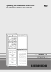
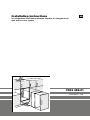
Installation instructions
for refrigerators, BioFresh appliances, freezers, for integrated use
with door-on-door system
GB
7082 452-01
IK/IKP/IKB/IG 2406
(mm)
mi
min. 2
38 n. 200 cm
4
200
560570
max. 2100
3
2
b
2
13mm
1
R
557
53
8
mi
38 n.
6
527
90
°
25
a
Torx
2
mi
55 n.
0
(mm)
A
min. 200 cm
Torx
R
8
3
10
11
2x
4x
1x
13
6
872
1022
1218
1395
1770
6
B
25 9
b
a
2
874- 890
1024-1040
1220-1236
1397-1413
1772-1788
16
14
1x
15
5
9
1x
1x
17 Torx R 25 18 Torx R 15 19
2x
10
7
Torx
20
26
27
1x
21
22
2x
Torx
C1
1x 1x
19 mm
*
23
R
20 2 x
7
1x
27
C3
SW 5
15
1x
2 x 28
6x
12 x
26
R
10
2 x 18 Torx R 15 28
R
2 x Torx 20 4 x
2x
9
10
A1
11
13
2
Torx
R
15
3
1
14
? mm
15
3
A2
1
Torx
R
15
D
=
=
m
X
Z
=
ca
.2
m
J1
Torx
R
25
34
Y
J2
33
32
J
Torx
R
33
25
26
26
Torx
R
15
27
Z
18
Torx
Torx
Torx
R
R
K
15
=
23
15
Torx
R
15
Torx
1
2
R
Torx
15
3
28
=
20
21
=
26
31
18
H
30
R
Torx
R
15
28
M
N
22
R
15
20
Installation instructions
Keep the installation instructions in a safe place and pass
them on to the next owner of your appliance where applicable.
The operating instructions apply to several
models. Differences may therefore occur.
Before reading, please fold out and refer
to the illustrated front page.
You additionally require the following tool for installation:
Cordless screwdriver Torx®15, 20, 25, spanner 13.
Changing the compartment door
W Fig.A2: At the hinge 1 fold away the cover.
Unscrew the hinge 1 and remove the compartment door
with the hinge.
W Unscrew the closure 2.
W Close the holes with the plugs 3.
W Rotate the door and closure by 180° and replace on the
other side: Insert the compartment door at the top, put the
hinge 1 in place at the bottom, screw down again and
close the cover.
Changing over door hinges
Fig. A1 The door hinges can be changed from one side to
the other if need be. Otherwise continue from "Installation
information", fig. B.
W To simplify installation, slide the appliance three-quarters
of the way into the recess. Open the door.
For models with soft stop 3* proceed according to fig. A
(otherwise continue according to fig. A1).
For appliances 870 mm high: remove the lower storage rack
for easier installation.
W Fig. A: Detach the soft stop mechanism:
Please note the soft stop mechanism contracts
in the detached state!
W Take hold of cover 1 at the back for removal,
bend it downwards a little and push it away to the side.
W Undo screw 2, while pressing the fork of the soft stop
mechanism downwards so that it cannot suddenly disengage.
W Carefully disengage the fork of the soft stop mechanism
from the hinge - the mechanism contracts!
W Unscrew the ball stud 4 together with the soft stop
mechanism from the door and set it aside.
W Fig. A1, lift off cover parts 5, 6and 7 in a forward
direction using a flat-blade screwdriver.
W Detail fig. A1.1: Loosen the attachment screws 8 on the
top and bottom of the body of the appliance.
- Pull the door outwards and remove.
W Transfer the attachment screws 8 to the other side and
screw in a little way.
W Fig. A1: Unscrew the door attachment screws 9 and
replace the hinges in the diagonally opposite corner.
NB: Do not fold the hinges together - danger of injury!
- Use a cordless screwdriver to screw down the hinges
- the screws 9 are self-tapping.
W Close the holes on the other side with the plugs bl.
W Suspend the appliance door in the ready inserted
screws 8 and tighten screws.
W Fig. A: Fit the soft stop mechanism 3* back in place:
Screw ball stud 4 together with soft stop mechanism into
the new fastening hole.
W Draw the fork out of the soft stop mechanism, put it over
the hinge and attach with the stud.
W Re-fasten with screw 3, while pressing the fork onto the
hinge so that it does not disengage.
Installation information
W This appliance can also be used to replace an existing
appliance.
In this case, remove the hinges on the unit door and in
the recess. They are no longer needed as the unit door is
fitted to the appliance door.
W Fig. B: Align the unit with a spirit level and an angle. If
necessary, level out by building up from underneath. The
shelf and side walls of the unit must be at right-angles to
one another.
W Fit the refrigerator/freezer in stable kitchen units only.
W The following ventilation gaps must be observed:
- The depth of the ventilation channel at the rear of the unit
must be at least 38 mm.
- There must be a ventilation space of at least 200 cm2
underneath and at the top of the unit. the greater the area
the more economically the appliance will run.
W Check installation dimensions in accordance with fig. B:
Appliance height a, recess height b
Connecting to the mains
Power supply (AC) and voltage
at the operating point must comply with the details on the
type plate. It is located inside the appliance on the left-hand
side.
W The appliance must be connected with a properly installed fused socket.
W The fuse of the plug has to be 10 A or more, it must be
situated away from the rear area of the appliance and be
easily accessible.
W Do not
- connect to stand-alone inverters,
- operate with so-called energy-saving plugs - this can
damage the electronic system.
- connect together with other appliances using an extension cable - danger of overheating.
W When removing the mains cable from the back of the
appliance, remove the cable holder to prevent vibration
noise.
W Fit all the cover parts back in place.
IK/IKP/IKB/IG
* Depending on model and options
5
GB
Installation instructions
Installation and fitting
Figs. C1-3:All installation components are supplied.
W Fig. D: Fit equaliser trim bm centered on the appliance:
slide into the channel and engage in the key holes.
W Route the mains cable with the aid of string 1 in such a way
that the appliance can be easily connected after installation.
W Slide the appliance three-quarters of the way into the
recess.
W Note the thickness of the unit walls:
For 16 mm unit wall (568 mm recess):
- Fig. D: Stick sealing strip bp onto the side of the appliance
on the handle side flush with the front: remove the protective film and stick on; shorten to recess height if necessary.
- Clip spacers boand bq onto the hinges.
- Fig. E: Slide appliance into the recess until the spacers
make contact with the side of the units, Fig. E1.
For 19 mm unit wall = 562 mm recess:
- Fig. E2: Slide the appliance into the recess until the fronts
of the hinges are flush with the sides of the unit walls; note
the additional space needed for units with door furniture
(knobs, sealing lips, etc.). Allow the hinges to protrude by
the additional distance required. Press the appliance on
the hinge side against the wall of the unit.
W Fig. E3: Level the appliance by adjusting the adjustable
feet with the spanner provided cn. Align the body of the
appliance parallel to the front edges of the side walls of the
unit.
W Screw plastic bracket br onto the handle side of the appliance with M5 screws bs.
- Make sure the front of the plastic bracket br is flush with
the front edge of the floor of the unit.
Do not forget the additional space required if the unit has
door furniture (knobs, sealing lips, etc.) and align parallel to
the front edge of the hinge.
W Fig. F: Screw the appliance into the recess.
- Figs. F1/2: Screw in with long wood board screws bu
through the hinge plates at the top and bottom.
- Fig. F3: Screw in temporarily with a long screw bu through
the middle of the long slot on the plastic bracket br. Fold
up the cover on the plastic bracket and close the appliance
door.
Fitting the unit door
W Fig. G1: Check the 8 mm default setting (distance between
appliance door and bottom edge of attachment strut).
W Fig. G: Slide the fitting aids dl up level with the unit door,
underside of stop edge ▲ of fitting aid = upper edge of unit
door
W Fit the attachment strut dm on the unit door:
- For this purpose, unscrew the strut by way of the counternuts dn fig.G
- Fig. H: Suspend the strut with the fitting aids dl on the
inside of the unit door and align centrally (draw a short line
in the middle of the unit door, align the arrow on the strut
with it keeping the same distance to outer edges on left
and right).
W Fasten the attachment strut dm in the centre:
- Fig. H: with at least 6 screws if the doors are made
of wood board,
- with 4 screws round the edge in the case of panel doors.
- Lift the fitting aids dl out to the top, turn round and insert
into the adjacent openings.
6
W Fig.J: Suspend the unit door on the door of the appliance/
adjusting pins do. Screw the counternuts dn loosely onto
the adjusting pins. Close the door.
W Fig. J1: Check the gap between the door and the surrounding unit doors.
- Fig. J2: Align the unit door flush with the surrounding unit
fronts: align laterally (X) by sliding in the corresponding
direction, adjust height (Y) and lateral tilt with the adjusting
pins do using a screwdriver.
- Tighten counternuts dn.
W Fig. K: Secure the mounting bracket cr to the pre-drilled
holes in the appliance door using the hexagonal screw cs.
W Screw the appliance door onto the unit door with the attachment brackets cr:
- Ensure that both metal edges are flush (symbol //). Drill attachment holes (making a hole with a bradawl) and screw
tight.
W Adjust the depth of the unit door (Z):
- Fig. J2: top: loosen screws dp,
- Fig. K: bottom: loosen the hexagonal screws cs with the
ring spanner co provided and adjust the door.
- Fig. J1: Allow an air gap of approx. 2 mm between the unit
door and the body of the unit. Do not allow knobs and sealing lips to make contact with the appliance as this can have
a detrimental effect on its function.
W Fig. L: If the unit door is large or divided into separate parts,
attach another pair of attachment brackets cr (accessories
bag, fig. C3).Use the pre-drilled holes in the handle area of
the appliance door.
W Check that the door is properly positioned, and readjust if
necessary. Tighten all screws.
- Fig. L1: Tighten the counternuts dn with the ring spanner co provided, holding the adjusting pins do in position
with a screwdriver.
W Fig. L2: If necessary, align the equaliser trim bm parallel
with the floor of the unit. It must not project.
W Fig. L3: Fix the appliance in the round hole at the bottom
with the second screw bu through the plastic bracket.
W Fig. M: Fit all the covers:
- Place the top cover cl in position and click into place.
- Place lateral cover cm in position, slide it to the limit, then
press on the cover until it audibly engages.
- Slide on cover ct laterally, draw the cover forwards using a
screwdriver according to fig. M so that it engages well into
place.
W Fig. N: The opening resilience of the door can now be
adjusted. Adjust using the no. 5 Allen key provided.
- Turn clockwise for stronger resilience.
- Turn anticlockwise for = weaker resilience (factory setting).
_______________________________________________
The manufacturer works constantly on the further development of all the types and models. Therefore please understand that we have to reserve the right to make design, equipment and technical modifications.
IK/IKP/IKB/IG