1
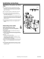
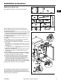
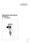
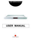
Installation instructions
for refrigerator-freezers, built-in flush
with decor frame
GB
7082 450-01
EK/EKB/EG 2606
Installation instructions
Keep the installation instructions in a safe place and pass
them on to the next owner of your appliance where
applicable.
The operating instructions apply to several models. Differences may therefore occur.
You additionally require the following tool for installation:
crosstip and Torx® screwdriver, 10, 15, 25
Changing over door hinges
Fig. A1: The door hinges can be changed from one side to
the other if need be. Otherwise continue from "Installation
information", fig. B.
W Fig. A1: Lift off cover parts 1, 2 and 3 in a forward
direction.
W Unscrew decor frame 4. Using a screwdriver, lift out
cover plate 5 and hinge pin 6.
W Open the door to an angle of about 45°, then tilt forwards
until the hinge 7 is completely free and lift off.
- If the appliance has a freezer compartment, now change
the compartment door. (see "Changing the compartment
door")
W Transfer the hinge 8 to the other side (screw in through
the second and fourth holes from the outside, using short
metric screws).
- Transfer the hinge pin 9 to the other side.
W Remove the plastic cover bl from the door mounting
and insert on the other side making sure it fits precisely.
Look out for the locking piston.
W Rotate the hinge 7 by 180° and transfer to the other side.
Knock the hinge in from the side!
W Replace the door on the hinge pin 9 at the bottom, guide
it across the hinge 7 at the top and insert hinge pin 6.
W Important - Replace the cover plate 5!
W Screw down decor frame 4. Mount decor panel
(if any, see below). Fit handle (occlude any holes used
with stoppers).
W Rotate cover parts through 180° and re-attach them to
the other side, 1, 2 and 3.
2
Torx
R
15
3
1
Changing the compartment door*
W Fig. A2: At the hinge 1 fold away the cover.
Unscrew the hinge 1 and remove the compartment door
with the hinge.
W Unscrew the closure 2.
W Close the holes with the plugs 3.
W Rotate the door and closure by 180° and replace on the
other side: Insert the compartment door at the top, put
the hinge 1 in place at the bottom, screw down again
and close the cover.
6
3
A2
* Depending on model and options
Torx
R
15
EK/EKB/EG
Installation instructions
Decor panel assembly
For appliances with decor frames, fig. B:
The front of your appliance can be colour-matched or contrasted with other components of a fitted kitchen
through the attachment of a decor panel and frame.
The following table shows the panel dimensions for your appliance:
Appliance for
Decor panel dimensions (mm)
recess height
height
width
max.
thickness
_______________________________________________
874 - 880
860
585
4
1220 - 1226
1206
585
4
GB
W Graduate thicker decor panels according to fig. B1.
br Decor frame
bs Decor panel
Assembly
W Unscrew decor frame br.
W Loosen decor frames bt/bu and slide forwards.
W Slide in decor panel bs.
W Slide all decor frames back and screw tight. Attach handle bq at required height (top or bottom - remove centre
screw if at top).
W Cover screw heads with cover caps cl
Equaliser trims for replacement
appliances
For appliances with decor frames, fig. C.
If the existing decor panel on the replacement appliance
is too short, you can adjust the height with equaliser trims
available in different heights.
Depending on the additional height required, or for visual
reasons, you can use either one or two equaliser trims
(top and/or bottom). The equaliser trims are available in
three different heights and colours (see table below) from
your customer service point.
Equalisation height
Part no.:
[mm]
h
brown
white
aluminium
_______________________________________________
16
9733032
9733035
9733050
41
9733033
9733036
9733051
60
9733034
9733037
9733052
Assembly
W Unscrew top and bottom decor frame br/bu. Just loosen
the decor frames bt at the side and push forwards.
W Slide in decor panel bs.
W Insert equaliser trims cm at top and/or bottom.
W Place decor frames br/bu over panel and screw tight
with retaining screws.
W Cover screw heads with cover caps cl
EK/EKB/EG
* Depending on model and options
7
Installation instructions
Installation information and dimensions
(mm)
W Fig. D: Align the unit with a spirit level and an angle.
If necessary, level out by building up from underneath.
The shelf and side walls of the unit must be at right-angles to one another.
a
872
1218
W Fit the refrigerator/freezer in stable kitchen units only.
- There must be a ventilation space of at least 200 cm2 underneath and at the top of the unit. The following principle
applies: the greater the area the more economically the
appliance will run.
887
1233
874- 880
1220-1226
m
in.
in.
m
2
mi
n. 200 cm 550
38
c
W Check installation dimensions in accordance with fig. D:
appliance height (carcass) a, door height b, recess
height c.
c
110
max. 2100
W The following ventilation gaps must be observed:
- The depth of the ventilation channel at the rear of the
unit must be at least 38 mm.
b
560570
mi
38 n.
1
557
90
593
54
2
a
b
Connecting to the mains
Power supply (AC) and voltage
min. 200 cm²
7
at the operating point must comply with the details
on the type plate. It is located inside the appliance on
the left-hand side.
W The appliance must be connected with a properly installed fused socket.
W The fuse of the plug has to be 10A or more, it must be
situated away from the rear area of the appliance and be
easily accessible.
W Do not
- connect to stand-alone inverters,
- operate with so-called energy-saving plugs - this can
damage the electronic system.
- connect together with other appliances using an extension cable - danger of overheating.
W When removing the mains cable from the back of the appliance, remove the cable holder to prevent vibration
noise.
D
W Route the mains cable with the aid of string 1 in such
a way that the appliance can be easily connected after
installation, fig. D.
8
* Depending on model and options
EK/EKB/EG
Installation instructions
Fastening in kitchen unit
W Fig. E1/2: All installation components are supplied.
GB
3
2x
1x
34
1x
o 4 x 19 Torx
38
1x
2x
37
39
M 5 x 15 Torx R 25 1x
19 mm
5 mm
30
F1
33
30
35
32
R
Torx
15
35
Torx
34
R
15
36
8
37
M5
Torx
38
R
15
34
R
25
F3
37
_______________________________________________
EK/EKB/EG
R
15 o 4 x 29 Torx 15
1x 1x
Torx
The manufacturer works constantly on the further development of all the types and models. Therefore please understand that we have to reserve the right to make design, equipment and technical modifications.
R
36
E2
2x
2 x 35
33
7,5 -15
W Slide appliance 3/4 of the way into the kitchen unit.
W Fig. F: slide equaliser trim dl into the channel and engage it in the key holes.
W Stick sealing strip dn onto the side of the appliance on the
handle side flush with the front: remove the protective film
and stick on; shorten to recess height if necessary.
W For 16 mm unit wall (568 mm recess): clip spacer do onto
the hinge in the slot.
W For19 mm unit wall (562 mm recess): the spacer is not
needed.
W Slide appliance into the recess until the lower hinge 8
abuts the end face of the unit wall, fig. F3.
W Check the fit of the appliance and the door. Align if necessary, fig. F:
- Using a spanner*, vertically align the appliance on the handle side by way of the adjustable foot* du. Pay attention to
the following:
- The appliance has to be tight-fitting against the side wall
at the top on the hinge side!
- Align the door so that it is in alignment with the surrounding unit doors by means of the elongated slots in the
lower hinge 8.
W Screw plastic bracket ds with M5 screws dt onto the appliance at the handle side, fig. F, and align so it is flush
with the front edge of the unit floor, fig. F2.
W Fasten/fix the appliance in the recess using chipboard
screws dp/dq: through top hinge, pressing the appliance firmly against the unit wall; at the bottom through
sleeve dr in the hinge 8 and plastic bracket ds
- If necessary, align the equaliser trim dl by moving it parallel to the ceiling of the unit - it must not be proud, fig. F1.
W Pay attention that all the screws have a tight fit!
32
30
39
F
F2
* Depending on model and options
9