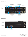
1
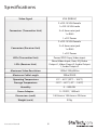
VGA Video Extender over Cat 5 with
Audio and RGB SKEW Calibration
ST122UTPAL
DE: Bedienungsanleitung - de.startech.com
FR: Guide de l'utilisateur - fr.startech.com
ES: Guía del usuario - es.startech.com
IT: Guida per l'uso - it.startech.com
NL: Gebruiksaanwijzing - nl.startech.com
PT: Guia do usuário - pt.startech.com
For the most up-to-date information, please visit: www.startech.com
Manual Revision: 07/12/2011
FCC Compliance Statement
This equipment has been tested and found to comply with the limits for a Class B digital device,
pursuant to part 15 of the FCC Rules. These limits are designed to provide reasonable protection
against harmful interference in a residential installation. This equipment generates, uses and can
radiate radio frequency energy and, if not installed and used in accordance with the instructions,
may cause harmful interference to radio communications. However, there is no guarantee that
interference will not occur in a particular installation. If this equipment does cause harmful
interference to radio or television reception, which can be determined by turning the equipment
off and on, the user is encouraged to try to correct the interference by one or more of the
following measures:
Reorient or relocate the receiving antenna.
Increase the separation between the equipment and receiver.
Connect the equipment into an outlet on a circuit different from that to which the receiver is
connected.
Consult the dealer or an experienced radio/TV technician for help.
Use of Trademarks, Registered Trademarks, and other Protected Names and Symbols
This manual may make reference to trademarks, registered trademarks, and other protected
names and/or symbols of third-party companies not related in any way to StarTech.com.
Where they occur these references are for illustrative purposes only and do not represent an
endorsement of a product or service by StarTech.com, or an endorsement of the product(s) to
which this manual applies by the third-party company in question. Regardless of any direct
acknowledgement elsewhere in the body of this document, StarTech.com hereby acknowledges
that all trademarks, registered trademarks, service marks, and other protected names and/or
symbols contained in this manual and related documents are the property of their respective
holders.
Table of Contents
Introduction.........................................................................................................................................................1
Packaging Contents.................................................................................................................................1
System Requirements.............................................................................................................................1
Side View 1.....................................................................................................................................................2
Side View 2.....................................................................................................................................................2
Installation............................................................................................................................................................3
Preparing Your Site....................................................................................................................................3
Installing the Local Unit.........................................................................................................................4
Installing the Remote Unit...................................................................................................................4
Driver Installation.......................................................................................................................................5
How to Use...........................................................................................................................................................5
Mode A Configuration............................................................................................................................6
Mode B Configuration............................................................................................................................6
EDID Copy......................................................................................................................................................6
Specifications......................................................................................................................................................8
Technical Support............................................................................................................................................9
Warranty Information.....................................................................................................................................9
Instruction Manual
i
Introduction
This VGA and audio over Cat5 video extender allows you to extend a VGA signal using Cat5
/ Cat5e cabling to 4 (2 local and 2 remote) monitors to be connected to a single PC. This
transmitter and receiver pair is unique because it offers a rotary control wheel that allows you
toggle on/off the display signal to connected display devies on the receiver and adjust audio
output volume. Plus, the rotary control wheel can be used to help you fine tune the video signal
by offering RGB (red, green, blue) skew calibration, gain, and equalizer controls.
Packaging Contents
• 1 x ST122UTPAL local unit
• 1 x ST122UTPAL remote unit
• 2 x Power Adapter
• 2 x Grounding Wire
• 1 x Instruction Manual
System Requirements
• VGA enabled display device
• VGA enabled video source
• Stereo audio source with 3.5mm mini-jack plug (optional)
• Stereo speakers with 3.5mm mini-jack plug (optional)
• Available electrical power outlet at local and remote locations
Instruction Manual
1
Side View 1
Power
connector
VGA/Audio
output 2
VGA/Audio
output 1
VGA/Audio
Input
VGA/Audio
output 1
RJ45
connector
Remote
Unit
Local Unit
Side View 2
Remote
Unit
Local Unit
EDID Copy button
VGA/Audio
output 2
Instruction Manual
2
Installation
NOTE: To prevent potential electrical damage to the units in some environments, ensure that
the chassis is properly grounded. Place cables away from fluorescent lights, air conditioners, and
machines that are likely to generate electrical noise.
This product is composed of two different units: the Local Unit and the Remote Unit. The Local
Unit takes the output from an analog audio and VGA video signal source (usually a computer)
and transmits it to the Remote Unit over UTP Ethernet cable. The remote display(s) (monitor,
projector, etc) and speaker(s) connect to the Remote Unit using standard VGA and 3.5mm minijack connections respectively and displays the image and audio from the local computer onto
the remote display(s) and speaker(s).
Preparing Your Site
1. Determine where the local computer will be located and set up the computer.
2. Determine where the remote display(s) will be located and place/mount them appropriately.
3. If you are using surface cabling, ensure you have enough unshielded twisted pair (UTP)
Ethernet cabling to connect the Local Unit to the Remote Unit’s location, and that each end is
terminated with a RJ45 connector. Make sure the cabling does not go through any standard
networking equipment (i.e. routers, modems, switches, etc).
OR
If you are using premise cabling, ensure that the unshielded twisted pair (UTP) Ethernet
Cabling between the Local Unit and the Remote Unit has been properly terminated in a wall
outlet in each location and there is a patch cable long enough to connect the Remote Unit
and the Local Unit to their respective outlets. Make sure the cabling does not go through any
standard networking equipment (i.e. routers, modems, switches, etc).
Instruction Manual
3
Installing the Local Unit
1. Make sure to power off any display devices and the video source device before attempting
the installation.
2. Place the Local Unit near the local video/audio source device.
3. Use a male/female DE-15 VGA cable (not included) to connect the VGA source device (i.e.
computer system) to the input on the ST122UTPAL transmitter unit. If using audio, connect a
3.5mm mini-jack cable from the audio input connector the audio source (i.e. sound card).
4. If using a local monitor, connect a VGA monitor to one of the output connectors on the
transmitter unit. If using audio, connect a set of speakers/headphones with a 3.5mm minijack connector to the audio output connector. Both sets of outputs on the Local unit are
identical.
5. Connect the UTP Ethernet cable to the RJ45 connector on the Local unit.
6. Connect the power adapter from an available power outlet to the Local unit.
Installing the Remote Unit
1. Connect the Remote Unit to the UTP cable connected from the Local Unit.
2. Connect a VGA cable from the remote display to one of the VGA output connectors on the
remote unit. If using audio, connect speakers to the 3.5mm mini-jack port from the same set
of outputs.
OPTIONAL: A second set of display and speakers can be connected to the Remote Unit via
the second set of outputs. Both outputs are identical.
3. Connect the Power Adapter (provided) into an appropriate power source and plug the
opposite end into the power connector on the Remote Unit.
CAUTION: The UTP Ethernet cables that connect the Local and Remote Units carry electrical
current and should not be plugged into any other devices, as they may cause damage. We
strongly recommend marking the Ethernet cables you are using with this product at both
locations for easy identification.
Instruction Manual
4
Driver Installation
No driver installation is required for the video extender as it is an external hardware-only
solution, invisible to the computer system.
How to Use
The rotary wheel on the Remote Unit is used to access the various features available on the video
extender. There are two configuration mode available.
Mode A: This mode allows for selection of the physical connector on the unit to adjust (VGA or
3.5mm mini-jack) as well as volume control and video ON/OFF.
Mode B: This mode allows for adjustments to the video signal output, including Equalization,
Gain and RGB skew calibration.
To activate the configuration modes, follow these steps:
1. After installing and powering on the Local and Remote units, the Power LED on the Remote
Unit should light up solid green.
2. Press and hold the rotary wheel on the Remote Unit for several seconds and the set of
LED indicators under Output 1 and 2 should start flashing. This indicates the unit is in
configuration Mode A.
3. Continuing to hold the rotary wheel for another several seconds will cause the Equalizer/
Gain/Skew LEDs to start flashing. This indicates the unit is in configuration Mode B.
4. Release the rotary wheel when the unit enters the desired configuration mode.
NOTE: The unit will return to normal operating mode if left idle for 20 seconds.
Instruction Manual
5
Mode A Configuration
When in Mode A, each press of the rotary wheel will switch between the different physical ports
available on the unit (VGA and audio). When selected to a video output, rotating the wheel will
toggle the output ON or OFF. When selected to an audio output, rotating the wheel will increase
or decrease the volume output accordingly. The LED strength will reflect the volume level (i.e.
brighter indicates higher volume).
Mode B Configuration
When in Mode B, each press of the rotary wheel switches between the different signal calibration
modes: equalization, gain, red skew, green skew and blue skew. Rotating the wheel in any of
these calibration modes will adjust the output signal accordingly.
NOTE: Before selecting Mode B, first enter Mode A and select a video output connector. Then
when entering Mode B, the video calibration will affect that output only. If using both outputs
on the Remote unit, this process will need to be done to both separately.
EDID Copy
In some cases display problems may arise due to incorrect EDID communication between the
display device and the computer graphics card or insufficient EDID data programmed into the
display device. The Local Unit provides an “EDID Copy” feature that allows the Local Unit to read
the necessary EDID information from the locally attached display device and then provide it, at
all times, to the attached video source. If no new EDID information is available from a display
device, a default profile built into the Local Unit is automatically provided.
Load Default EDID
When using a non-EDID compliant display device, the ST122UTPAL can automatically select
viable EDID data from the Unit’s default EDID profile to set the EDID information up. Users can
enable this default EDID profile by following the instructions below:
1. Press and Hold the button “EDID Copy” on the side panel of the Local Unit.
2. Plug in the provided power adapter to the Local Unit, while still holding the button.
3. Release the “EDID Copy” button immediately after one confirmation beep. The power LED
light will be steady green, indicating that the EDID copy (communication) is completed and
the default profile loaded.
Instruction Manual
6
4. Connect the monitor(s) to the output port on the Local Unit. The Local Unit is ready to
operate now.
Copy EDID (Port 1 only)
When using an EDID compliant display device, the ST122UTPAL’s EDID Copy function will enable
proper EDID communication between the monitor and the computer’s video card for optimal
video quality. Users can enable this EDID communication by following the instructions below:
1. Plug in the provided power adapter to the Local Unit.
2. Connect the EDID compliant display device to the “Port 1” output on the Local Unit.
3. Press and hold the “EDID Copy” button on the side panel of the Local Unit for about two (2)
seconds. Release button “EDID Copy” immediately after two confirmation beeps.
4. If one long beep occurs, it means that the display device is not properly connected to “Port 1”
on the Local Unit or does not contain proper EDID information. Please repeat Step2 to 3 to try
again or attempt with a different display device.
Instruction Manual
7
Specifications
Video Signal
VGA (RGBHV)
2 x DE-15 VGA female
1 x DE-15 VGA male
Connectors (Transmitter Unit)
3 x 3.5mm mini-jack
1 x RJ45
1 x DC Power
2 x DE-15 VGA female
2 x 3.5mm mini-jack
Connectors (Receiver Unit)
1 x RJ45
1 x DC Power
LEDs (Transmitter Unit)
Power/EDID Copy, Video input
LEDs (Receiver Unit)
Skew/Video Input, Gain, EQ, Video
Output 1, Video Ouput 2, Audio Output
1, Audio Output 2
Maximum Video Resolution
1920x1200@300m
Maximum Cable Length
300m/950ft
Operating Temperature
0°C ~ 40°C (32°F ~ 104°F)
Storage Temperature
-20°C ~ 60°C (-4°F ~ 140°F)
Humidity
0 ~ 80% RH
Power Adapter
9~12VDC, 1500mA
Dimensions (each)
140.0mm x 104.6mm x 23.0mm
Weight (each)
970g
Instruction Manual
8
Technical Support
StarTech.com’s lifetime technical support is an integral part of our commit-ment to provide
industry-leading solutions. If you ever need help with your product, visit www.startech.com/
support and access our comprehensive selection of online tools, documentation,
and downloads.
Warranty Information
This product is backed by a two year warranty.
In addition, StarTech.com warrants its products against defects in materials and workmanship for
the periods noted, following the initial date of purchase. During this period, the products may
be returned for repair, or replacement with equivalent products at our discretion. The warranty
covers parts and labor costs only. StarTech.com does not warrant its products from defects or
damages arising from misuse, abuse, alteration, or normal wear and tear.
Limitation of Liability
In no event shall the liability of StarTech.com Ltd. and StarTech.com USA LLP (or their officers,
directors, employees or agents) for any damages (whether direct or indirect, special, punitive,
incidental, consequential, or otherwise), loss of profits, loss of business, or any pecuniary loss,
arising out of or related to the use of the product exceed the actual price paid for the product.
Some states do not allow the exclusion or limitation of incidental or consequential damages. If
such laws apply, the limitations or exclusions contained in this statement may not apply to you.
Instruction Manual
9
Hard-to-find made easy. At StarTech.com, that isn’t a slogan. It’s a promise.
StarTech.com is your one-stop source for every connectivity part you need. From
the latest technology to legacy products — and all the parts that bridge the old
and new — we can help you find the parts that connect your solutions.
We make it easy to locate the parts, and we quickly deliver them wherever they
need to go. Just talk to one of our tech advisors or visit our website. You’ll be
connected to the products you need in no time.
Visit www.startech.com for complete information on all StarTech.com products
and to access exclusive resources and time-saving tools.
StarTech.com is an ISO 9001 Registered manufacturer of connectivity and technology
parts. StarTech.com was founded in 1985 and has operations in the United States,
Canada, the United Kingdom and Taiwan servicing a worldwide market.