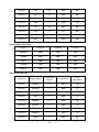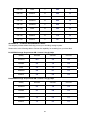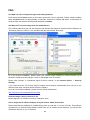
1
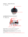
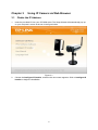
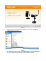
TL-SC3171G
Wireless Day/Night Surveillance Camera
REV: 1.0.0
1910010292
COPYRIGHT & TRADEMARKS
Specifications are subject to change without notice.
is a registered trademark
of TP-LINK TECHNOLOGIES CO., LTD. Other brands and product names are trademarks or
registered trademarks of their respective holders.
No part of the specifications may be reproduced in any form or by any means or used to make any
derivative such as translation, transformation, or adaptation without permission from TP-LINK
TECHNOLOGIES CO., LTD. Copyright © 2010 TP-LINK TECHNOLOGIES CO., LTD.
All rights reserved.
http://www.tp-link.com
FCC STATEMENT
This equipment has been tested and found to comply with the limits for a Class B digital device,
pursuant to part 15 of the FCC Rules. These limits are designed to pro-vide reasonable protection
against harmful interference in a residential installation. This equipment generates, uses and can
radiate radio frequency energy and, if not in-stalled and used in accordance with the instructions,
may cause harmful interference to radio communications. However, there is no guarantee that
interference will not occur in a particular installation. If this equipment does cause harmful
interference to radio or television reception, which can be determined by turning the equipment off
and on, the user is encouraged to try to correct the interference by one or more of the following
measures:
¾
Reorient or relocate the receiving antenna.
¾
Increase the separation between the equipment and receiver.
¾
Connect the equipment into an outlet on a circuit different from that to which the receiver
is connected.
¾
Consult the dealer or an experienced radio/ TV technician for help.
This device complies with part 15 of the FCC Rules. Operation is subject to the following two
conditions:
1)
This device may not cause harmful interference.
2)
This device must accept any interference received, including interference that may cause
undesired operation.
Any changes or modifications not expressly approved by the party responsible for compliance
could void the user’s authority to operate the equipment.
Note: The manufacturer is not responsible for any radio or tv interference caused by unauthorized
modifications to this equipment. Such modifications could void the user’s authority to operate the
equipment.
CE Mark Warning
This is a class B product. In a domestic environment, this product may cause radio interference, in
which case the user may be required to take adequate measures.
CONTENTS
Package Contents.........................................................................................................................1
Chapter 1
Minimum System Requirements .............................................................................2
Chapter 2
Physical Overview....................................................................................................3
2.1
2.2
Front View ......................................................................................................................3
Bottom view....................................................................................................................3
Chapter 3
3.1
3.2
3.3
Obtain the IP Address ....................................................................................................5
Windows Web Browser ..................................................................................................7
Mac Web Browser ..........................................................................................................9
Chapter 4
4.1
4.2
4.3
4.4
4.5
Using IP Camera via Web Browser .........................................................................5
Using IP Camera via Mobile Phone ......................................................................12
3G Streaming Mobile View Mode .................................................................................12
3G Web Brower Mobile View Mode..............................................................................14
2.5G WAP Browser Snapshot Mode ............................................................................16
2.5G Web Browser Snapshot Mode .............................................................................16
Mobile View on Windows Mobile 6 Smart Phone .........................................................16
Chapter 5
Configuration of Main Menu..................................................................................20
5.1
Live View......................................................................................................................20
5.1.1
Snapshot..............................................................................................................20
5.1.1
Zoom in/out the image via the monitor window ....................................................21
5.1.2
Video play buttons................................................................................................21
5.1.3
Audio buttons .......................................................................................................21
5.2
Setting ..........................................................................................................................22
5.3
Client Setting................................................................................................................23
5.3.1
Mode ....................................................................................................................23
5.3.2
View Size .............................................................................................................23
5.3.3
Protocol................................................................................................................24
5.3.4
Video Buffer .........................................................................................................24
5.4
Image Setup.................................................................................................................24
5.4.1
Brightness ............................................................................................................24
5.4.2
Contrast ...............................................................................................................25
5.4.3
Saturation.............................................................................................................25
5.4.4
Hue ......................................................................................................................25
5.4.5
Default..................................................................................................................25
Chapter 6
Setting-BASIC.........................................................................................................26
6.1
System .........................................................................................................................26
6.1.1
Information ...........................................................................................................26
6.1.2
Date/Time.............................................................................................................27
6.1.3
Initialize ................................................................................................................28
6.2
Camera ........................................................................................................................29
6.2.1
General ................................................................................................................29
6.2.2
MPEG4 ................................................................................................................30
6.2.3
MJPEG.................................................................................................................33
6.3
Network ........................................................................................................................34
6.3.1
Information ...........................................................................................................35
6.3.2
PPPoE (Point-to-Point Protocol over Ethernet) ....................................................37
6.3.3
DDNS (Dynamic DNS) .........................................................................................39
6.3.4
UPnP (Universal Plug and Play) ..........................................................................42
6.3.5
Bonjour.................................................................................................................43
6.3.6
IP Notification .......................................................................................................44
6.3.7
Wireless ...............................................................................................................46
6.3.8
Messenger ...........................................................................................................49
6.4
Security ........................................................................................................................54
6.4.1
Account ................................................................................................................55
6.4.2
HTTPS .................................................................................................................56
Chapter 7
Setting-Advance.....................................................................................................58
7.1
FTP client .....................................................................................................................58
7.1.1
General ................................................................................................................59
7.1.2
Alarm sending ......................................................................................................59
7.1.3
Periodical sending................................................................................................62
7.2
SMTP ...........................................................................................................................64
7.2.1
General ................................................................................................................64
7.2.2
Alarm sending ......................................................................................................67
7.2.3
Periodical sending................................................................................................70
7.3
HTTP event ..................................................................................................................72
7.3.1
General ................................................................................................................73
7.3.2
Alarm sending ......................................................................................................73
7.4
Alarm output.................................................................................................................76
7.4.1
Setting..................................................................................................................77
7.5
Schedule ......................................................................................................................79
7.5.1
Setting..................................................................................................................80
7.6
Alarm input ...................................................................................................................81
7.6.1
Setting..................................................................................................................81
7.7
Motion detection...........................................................................................................82
7.7.1
Setting..................................................................................................................83
7.8
System Log ..................................................................................................................83
7.8.1
Setting..................................................................................................................84
Appendix .....................................................................................................................................85
FAQ ..............................................................................................................................................89
Package Contents
The follow items should be found in your package:
¾
TL-SC3171G Wireless Day/Night Surveillance Camera
¾
Power Adapter
¾
Mounting Bracket with three screws, a Lock Ring, a Brace and a Base Plate
¾
RJ45 Cable
¾
Quick Installation Guide
¾
Resource CD, including:
z
This User Guide
z
Other helpful information
) Note:
Make sure that the package contains the above items. If any of the listed items are damaged or
missing, please contact your distributor.
1
Chapter 1
Minimum System Requirements
We strongly recommend your computers follow our minimum requirements in order to use this
IP-Camera normally. If your computer doesn’t meet these requirements below, it might cause
some problems.
Item
Requirements
CPU
Pentium 4 1600MHz (or equivalent AMD)
Graphic
Card
64 MB RAM graphic cards(or equivalent on-board graphic cards)
RAM
512 MB
Operating
System
Windows 98, Windows ME (Please see
) Note)
Windows2000, 2003, XP, Vista, Mac OS X Leopard, Linux
Windows OS: Internet Explorer, Safari, Firefox, Google Chrome, Opera, Maxthon
Web
Browser
MAC OS: Safari, Firefox
Linux OS: Firefox
) Note:
1)
If you are using Windows 98 or Windows ME, please install IP Installer before using WEB UI
to ensure the system runs normally.
2)
If you can't view the record video file, please install Xvid codec while installing Intelligent IP
Installer. (For Windows 98, ME or 2000 server, the codec might not work properly. You’ll need
to download Xvid codec 1.0 from the Internet.)
3)
Please always update the latest Windows component. (Net Framework, Windows Media
Player, Enhance ActiveX Security)
2
Chapter 2
2.1
Physical Overview
Front View
Focus Adjustment Ring
Built-in Microphone
Figure 2-1
Focus Adjustment Ring: Adjust the focus to get a clear image.
Built-in Microphone: Built-in microphone for two-way audio.
2.2
Bottom view
Wireless Antenna
Audio In
Audio Out
Power Connector
Network Connector
Reset
I/O Terminal Connector
Power LED Indicator
Figure 2-2
Wireless Antenna: For connection of IEEE 802.11b/g wireless network.
Audio In: To support audio in with Microphone for two way audio.
Audio Out: To support audio out with earphones or speakers for two way audio.
Power Connector: For connection of 12V DC input.
Power LED Indicator: Power LED will light up after completing the boot process.
Reset: To successfully restore the camera to factory defaults, please keep the device powered on,
3
then press and hold the Reset Button for at least 10 seconds. The CPU of the camera starts to
work completely 1 minute after you release the Reset button.
I/O Terminal Connector: Input/Output to support External Alarm and Sensor used for motion
detection, event triggering and alarm notification, etc.
Network Connector: For connection to the Ethernet via RJ45 standard.
4
Chapter 3
3.1
1.
Using IP Camera via Web Browser
Obtain the IP Address
Insert the provided CD into your CD-ROM driver. The Setup Wizard will automatically pop up
on your computer’s screen as shown in the figure below.
Figure 3-1
2.
Choose the Intelligent IP Installer, and then the next screen appears. Click on Intelligent IP
Installer to begin the installation.
5
Figure 3-2
3.
After the installation is finished, click Start > Program Files > TP-LINK >Intelligent IP
Installer to start using the program.
Figure 3-3
4.
The following screen will then display. Click the Search button to search Network Cameras in
the network; it displays Network Cameras information including IP Address.
6
Figure 3-4
3.2
1.
Windows Web Browser
Click Link to IE button in Figure 3-4 or launch your web browser, and enter the IP address
(obtain from Figure 3-4Figure 3-4) of the IP camera in the Location / Address field of your
browser.
) Note:
1)
For the first time login with IE, you will need to enable “Download signed ActiveX controls”.
Please go to Tool→Internet Options…→Security→Custom Level… and find Download
signed ActiveV controls to prompt it. For detailed information, please refer to the Quick
Installation Guide.
2)
If you only want to view the video without setting page, enter “http://<IP>/index2.htm” as your
web URL . For example, you can enter “http://192.168.1.100/index2.htm” as your web URL to
view the video without setting page.
2.
Enter the default User name “admin” and password “admin” in the login window as shown
7
below.
Figure 3-5
) Note:
The default User name “admin” and Password “admin” are set at the factory for the administrator.
You can change them in the Account Menu (Please check “SETTING → BASIC → Security →
Account”).
3.
The web-based management page will display on your screen. On the leftmost column of the
web-based management page are Setting, Client Setting, and Image Setup. For more
details, you can refer to Section 5.2 Setting, Section 5.3 Client Setting and Section 5.4
Image Setup.
Figure 3-6
8
3.3
1.
Mac Web Browser
Click the Safari icon on the screen as the figure below shown, and enter the IP address of the
IP camera (which can be obtained from Figure 3-4) in the Location / Address field of your
browser.
) Note:
If you only want to view the video without setting page, enter “http://<IP>/index2.htm” as your web
URL. For example, you can enter “http://192.168.1.100/index2.htm” as your web URL to view the
video without setting page.
Figure 3-7
9
2.
Enter the default User name “admin” and password “admin” in the dialog box as shown below.
Figure 3-8
) Note:
The default Name “admin” and Password “admin” are set at the factory for the administrator. You
can change them in the Account Menu (Please check “SETTING → BASIC → Security →
Account”).
10
3.
The web-based management page will be display on your screen. In the leftmost column of
the web-based management page are Setting, Client Setting, and Image Setup. For more
details, you can refer to Section 5.2, Section 5.3 and Section 5.4.
Figure 3-9
11
Chapter 4
Using IP Camera via Mobile Phone
You can use TP-LINK Web User Interface via mobile phones. To use IP cameras via mobile
phones, please make sure your RTSP is set to “On” (Default is “On”). To change the settings of IP
cameras, Please check “Settings → Basic → Camera → General”. Up to the 15th August, it has
been tested that you can use TP-LINK Web User Interface via mobile phones supporting the
mobile view modes shown in the table below.
Tested Mobile Phone
Brand
Model
Nokia
N76
Nokia
N82
Nokia
N95
Nokia
E66
Nokia
5800
Nokia
6680
Apple
iPhone 3G
SonyEricsson
K310i
SonyEricsson
K618i
SonyEricsson
C905
SonyEricsson
W550i
SonyEricsson
W580i
Motorola
W220
Motorola
W510
Motorola
E6
HTC
Touch
Windows Mobile 6 Smart
Phone
Tested Mobile View Mode
3G
Streaming
Mobile View
3G Web Brower
Mobile View
●
●
●
●
●
●
2.5G WAP
browser
Snapshot
2.5G Web
browser
Snapshot
●
●
●
●
●
●
●
●
●
●
●
●
●
●
●
▲
■
●
▲ Please install Platform4 Player on your phone first.
■ Please install Opera Mobile 9.5 on your phone first.
● Please use Real Player and other RSTP streaming media player embedded to view the video
in this mode.
● Please use the normal embedded browser in the phone to view the video in this mode.
) Note:
You can have the latest supporting phones information on our website www.tp-link.com.
4.1
3G Streaming Mobile View Mode
For 3G Streaming Mobile View Mode, please type “rtsp://<IP>:<PORT>/video.3gp ” into your 3G
Streaming Link. <IP> is the IP address of your IP camera (which can be obtained from Figure 3-4);
<PORT> is the RTSP port of your IP camera (Default value is 554). For Example:
rtsp://192.168.1.100:554/video.3gp.
12
) Note:
You can also use RTSP clients (RealPlayer, VLC, QuickTime Player etc) to view RTSP streaming,
just type in “rtsp://<IP>:<PORT>/video.3gp” as the Player URL.
Below is an example of viewing the camera in 3G streaming mode on NOKIA N76:
1. Click Function and select Gallery.
2. Click the Streaming links.
3. Click Option and add a New link.
4. Type the New link Name and Web address. (The address is Public IP or domain name), Ex:
rtsp://tl-sc3130.dyndns.org/video.3gp
13
5. Open with Real-Player and click Yes to connect.
4.2
3G Web Brower Mobile View Mode
For 3G Web Browser Mobile View Mode, please type “http://<IP>” into your 3G Mobile’s Web
Browser. <IP> is the Public IP address of your IP camera (which can be obtained from Figure
3-4Figure 3-4); For Example: rtsp://192.168.1.100:554/video.3gp
Below is an example of viewing the camera in 3G Web Browser Mobile View Mode on iPhone 3G:
1.
Select Safari function
2.
14
Enter IP address in your web link
3.
Enter name and password. Default
values are both admin. Then click Log
in.
4.
The TP-LINK User Interface and live
image will show up in the middle of the
screen.
) Note:
It will show continuous snapshots not a real
time video streaming. Therefore, the recording
feature is disabled.
15
4.3
2.5G WAP Browser Snapshot Mode
For 2.5G WAP Browser Snapshot Mode, please type “<IP>/mobile.wml” into your 2.5G WAP
Browser. <IP> is the IP address of your IP camera, which can be obtained from Figure 3-4.
4.4
2.5G Web Browser Snapshot Mode
For 2.5GWeb Browser Snapshot Mode, please type “<IP>/mobile.htm” into your 2.5G Web
Browser. <IP> is the IP address of your IP camera, which can be obtained from Figure 3-4.
) Note:
Through 2.5G WAP or Web browser, you can only get the snapshot of the camera, not the video.
4.5
Mobile View on Windows Mobile 6 Smart Phone
The tested Smart Phones installed with Windows Mobile 6 OS are HTC smart mobile phone and
HP PDA. Below is the example, and the Platform4 Player and Opera Mobile 9.5 can be
downloaded from our website http://www.tp-link.com.
To use IP Camera via HP PDA, please take the following steps:
1. For HP iPDA HSTNH-L05C-WL, you need to install the free software Platform4 Player first.
Click the program Platform4 Player.
2. Click the setting and type rtsp link in Open Url field. Ex: rtsp://tl-sc3130.dyndns.org/video.3gp.
16
3. Click Setting I and select protocol with TCP.
4. Click Setting II and select System Settings.
5. Click OK and connect to IP Camera.
17
To use IP Camera via Opera Mobile with Windows Mobile Smart Phone, please take the following
steps:
1. Download the ”Opera Mobile 9.5.cab“ and copy to Windows Mobile 6 Smart Phone.
2. Click the “Windows Explorer” to find the download cab file.
3. Click the cab file to install the Opera Mobile 9.5.
4. Click Programs to find the Opera 9.5 icon.
18
5. Type IP or http url link.
6. Type the username and password or setup authentication off in Setting > Basic > Security >
Account.
19
Chapter 5
Configuration of Main Menu
You would find that the illustrative web pages in this Manual are all orange. Please note that
they're from our latest firmware, which can be downloaded from our website. Web pages in our
previous firmware are blue.
On the leftmost column of the web-based management page are Setting, Client Setting, and
Image Setup. For more details, you can refer to Section 5.2 Setting, Section 5.3 Client Setting,
Section 5.4 Image Setup.
Snapshot
Video Play
Audio button
Full screen
Zoom in / Out
On the right column of the web-based management page, you can use Live View. There are four
different functions which are Snapshot, Zoom, Audio and Video Play. You can see more details
as follows.
5.1
Live View
5.1.1 Snapshot
You can capture a still image shot by the camera and save it in your computer.
Symbols
Meaning
click to display a snapshot window
Save
Image
to save the picture in your computer
Close
to return to the view page
full Screen
20
5.1.1 Zoom in/out the image via the monitor window
z
Click
to display the digital zoom in window.
z
Pull
showed on the above window.
z
You can use the left click of your mouse to move the
view the desired detail more clearly.
to adjust the digital zoom range, and it will be
to any where on the window to
5.1.2 Video play buttons
Symbols
Meaning
Pause the current video
Play the video
Stop the current video
Record the current video
5.1.3 Audio buttons
Symbols
Meaning
Speakers turned on
) Note
mean the speakers of your computer are
turned on to transmit the sounds from the
connected IP camera(s)
Speakers turned off
21
Microphone turned on
mean you can broadcast to the connected
IP camera(s) via the Ethernet using your
microphone
Microphone turned off
Volume control bar
5.2
Setting
This function is only for the Administrator. Click this button to get into the Basic and Advance
settings menus.
There are four sub-menus under the BASIC menu, which includes System, Camera, Network,
and Security. For more information, you can refer to Section 6.1 System, Section 6.2 Camera,
Section 6.3 Network and Section 6.4 Security.
There are eight sub-menus under the Advance menu, which includes FTP Client, SMTP, HTTP
event, Alarm output, Schedule, Alarm input, Motion detection, and System Log. Fore more
information, you can refer to Section 7.1, Section 7.2, Section 7.3, Section 7.4, Section 7.5,
Section 7.6, Section 7.7 and Section 7.8.
22
5.3
Client Setting
This function is only for the client.
Click this button to configure the settings of IP Camera, which includes Mode, View size,
Protocol, and Video buffer.
5.3.1 Mode
Click the drop-down list to choose MPEG4, MJPEG and JPEG video compression mode.
) Note:
MJPEG streaming is unavailable if RTSP mode is On (Please check SETTING → BASIC →
Camera → General).
5.3.2 View Size
Select the desired display image resolution to 640*480 or 320*240. It is suggested that you go to
Client Setting to select a suitable View Size before using the IP camera as shown in the figure
below. For the PC whose resolution is less than 1280*1024, View Size of 320*240 is
recommended.
23
5.3.3 Protocol
Select the transferring protocol from TCP, UDP, HTTP and Multicast.
) Note:
This item appears only when RSTP mode is enabled (selecting SETTING → BASIC → Camera
→ General).
5.3.4 Video Buffer
Turn the Video Buffer function ON / OFF. The Video Buffer function makes the streaming more
smoothly in unsteady network environment, but might cause a little delay in live viewing.
5.4
Image Setup
You can use the tool bar to optimize video Brightness, Contrast, Saturation and Hue.
5.4.1 Brightness
The higher value the brightness is, the brighter the image is.
24
5.4.2 Contrast
The contrast is a measure of a display system, defined as the ratio of white to black that the
system is capable of producing. The higher value the contrast is, the more delicate color you can
get.
5.4.3 Saturation
The saturation of a color is determined by a combination of light intensity and how much it is
distributed across the spectrum of different wavelengths. The higher value the saturation is, the
more colorful the image will be.
5.4.4 Hue
Hue is one of the three main attributes of perceived color, which is affected by different wavelength
of color. With higher value of hue, color will be much more vivid.
5.4.5 Default
After the adjustment of all settings, you can still click Default to make the setting back to the
factory default settings.
25
Chapter 6
Setting-BASIC
Click BASIC to display the submenus including System, Camera, Network, and Security.
6.1
System
Click System to display the submenus including Information, Date/Time, and Initialize.
6.1.1 Information
The Information page provides the basic information of the product which includes Product name,
Firmware version and Web version.
26
6.1.2 Date/Time
The Date/Time page displays all options of time setting.
¾
Current date/time: Displays the current date and time of this IP Camera.
¾
PC clock: Displays the date and time of the monitoring PC clock.
¾
Date/time format: You can click the drop-down list to select different time display formats.
¾
Adjust: You can select one of those four adjusting modes for your IP Camera.
z
Keep current setting: Select this mode to keep the current date and time of this IP
Camera.
z
Synchronize with PC: Select this mode to keep the date and time of this IP Camera the
same with the monitoring PC.
z
Manual setting: Select this mode to adjust manually the date and time of this IP Camera.
z
Synchronize with NTP: Specify the NTP server name and the Refresh Interval to
27
synchronize the date and time of this IP Camera with those of the time server, known as
the NTP server.
) Note:
The NTP server (Network Time Protocol) is the time server which is an Internet standard
protocol built on the top of TCP / IP. This assures accurate synchronization to the millisecond
of computer clock time in a network of computers.
z
Time zone: You can select the format from Greenwich Mean Time. The time displayed
will be the same as the current date / time option.
z
Daylight Saving Time (DST; also summer time in British English): It is the practice of
advancing clocks so that afternoons have more daylight and mornings have less. Here
you can find the daylight saving time around the world:
http://en.wikipedia.org/wiki/Daylight_saving_time_around_the_world
6.1.3 Initialize
¾
Reboot: Click this button to reboot this IP Camera. A confirmation dialogue will appear and
then click OK to process. It takes two minutes to reboot this IP Camera.
¾
Factory default: Click this button to reset this IP Camera to the factory default settings. A
confirmation dialogue will appear and then click OK to process. The network LED indicator on
the IP Camera will start to blink. This IP Camera will reboot automatically after the restoring
has been finished. Don't turn off this IP Camera during this process.
¾
Backup setting data: You can save configuration setting data of this IP Camera into a file.
Click Save and follow the instructions on the browser to save this setting data file to specified
location.
¾
Restore setting: Download the saved setting data of this IP Camera. Click Browse… and
select the saved file. Click OK and this IP Camera is adjusted according to the loaded data
and then restarted.
¾
Firmware upgrade: Upgrade the device software. Click Browse… and select the file for
upgrading. A confirmation dialogue will appear. Click OK to start. This IP Camera will reboot
after upgrading has been finished.
) Note:
Use only upgrade files that are special for this IP Camera. Otherwise problems may occur. Don't
28
turn off the IP Camera power or disconnect the network until the upgrading is completed.
¾
6.2
Upload language pack: Upgrade the device language pack. Click Browse… and select
the file for upgrading. A confirmation dialogue will appear. Click OK to start upgrading. The
upgrade is applied immediately. The default language is “English”.
Camera
Click Camera to display the submenus including General, MPEG4 and MJPEG.
6.2.1 General
29
¾
RTSP: Switch On or Off.
z
RTSP Port: Specify the transmission port number of RTSP streaming. The default value
is 554.
z
Port Range: Specify the transmission port range of RTP streaming video. RTP will select
a port randomly from this range.
) Note:
RTSP (Real Time Streaming Protocol) is a protocol used in streaming media system which allows
clients to remotely control a streaming video server. RTSP is supports by most of the media clients
such as Real Player, QuickTime and VLC...etc.
¾
Image rotated: You can mirror or flip the display screen.
¾
Audio Codec: Switch On or Off.
¾
Exposure mode: You can choose Auto, 50Hz or 60Hz. If you choose Auto option, the camera
will adjust automatically to perform well.
¾
White Balance: You can choose the white balance to Auto, Sunny, Cloudy and Black &
White.
¾
IR: You can choose Auto, On or Off. If you choose Auto option, the camera will adjust
automatically to perform well.
) Note:
1) The effective range of the IR (Infrared) light is 10 meters (33 feet), and it is strongly suggested
that you install it in a place without any barriers within 3 meters of the field of view (10 feet).
Reflected light from a large closed barrier (such as a wall) may cause the camera to shut down
the infrared light.
2) Normally, 10 seconds after the environment becomes darker than the threshold, the camera
will turn on the IR (Infrared) light. One typical abnormal situation is that a barrier is very close
to the camera and shields all available light.
¾
Overlay:
z
Text Overlay: You can see some information on the display screen which includes
Date/Time and user-defined text. Also, you can change the background color.
z
Privacy Mask: You can cover a specific area of the video image.
6.2.2 MPEG4
A.
Computer View
If RTSP is On (see Setting →Basic → Camera → General), the screen will display as shown
below.
30
¾
Viewer Authentication: If the viewer authentication is On, the users will be requested to type
in username and password when viewing through RTSP.
¾
Multicast Streaming (If it is ON)
z
Multicast address: Specify the multicast server address.
z
Video/Audio port: Specify the transmission port number of the video data, which is an
even number from 1024 to 65534.
z
Time-To-Live: Set the maximum TTL (Transistor-Transistor Logic) that multicast can
pass through.
¾
Image Size: Specify the image size when the network camera transmits. You can choose
among 640 x 480, 320 x 240, and 160 x 120.
¾
Frame rate: Set the frame rate of the MPEG4 image. You can choose values from 1, 2, 3, 4,
5, 7, 10, 15, 20, 25, and 30 fps. The unit “fps” stands for “frames per second”.
¾
Quality:
z
Auto: The quality and bitrate will be adjusted automatically according to the frame rate.
z
Fixed Quality: You can select the value of quality among Medium, Standard, Good,
Detailed and Excellent.
z
Fixed bitrate: Set the bitrate of MPEG4 image transmission for a line. You can select the
values from 64, 128, 256, 384, 512, 768, 1024, 1280, 1536, and 2048 kbps.
If RTSP is Off (see Setting →Basic → Camera → General), the screen will display as shown
below.
31
B.
Mobile View
If RTSP is On (see Setting →Basic → Camera → General), the screen will display as shown
below.
¾
Viewer Authentication: If the viewer authentication is On, the users will be requested to type
in username and password when viewing through RTSP.
¾
Multicast Streaming (If it is On)
z
Multicast Address: Specify the multicast server address.
z
Video/Audio Port: Specify the transmission port number of the video data, which is an
32
even number from 1024 to 65534. It is set to 10000 and 11000 by default.
z
Time-To-Live: Set the maximum TTL(Transistor-Transistor Logic) that multicast can pass
through.
¾
Image Size: The image size of Mobile View is fixed at 160 x 120.
¾
Frame Rate: Set the frame rate of the MPEG4 image. You can choose values from 5, 10fps.
The unit “fps” stands for “frames sent per second”.
¾
Quality:
z
Auto: The quality and bitrate will be adjusted automatically according to the frame rate.
z
Fixed Quality: You can select the value of quality among Medium, Standard, Good,
Detailed and Excellent.
z
Fixed bitrate: Set the bitrate of MPEG4 image transmission for a line. You can select the
values from 16, 32, 48, 64, 128, 256bps.
If RTSP is Off (see Setting →Basic → Camera → General), the screen will display as shown
below.
6.2.3 MJPEG
If RTSP is On (see Setting →Basic → Camera → General), the screen will display as shown
below.
33
If RTSP is Off (see Setting →Basic → Camera → General), the screen will display as shown
below.
¾
Image Size: Specify the image size when the network camera transmits. You can choose
among 640 x 480, 320 x 240, and 160 x 120.
¾
Frame Rate: Set the frame rate of the MJPEG image. You can choose values from 1, 2, 3, 4,
5, 7, 10, 15fps. The unit “fps” stands for “frames per second”.
¾
Quality:
6.3
z
Auto: The quality will be automatically decided.
z
Fixed Quality: You can select the value of quality among Medium, Standard, Good,
Detailed and Excellent.
Network
Click Network to display the submenus including Information, PPPoE, DDNS, UPnP, Bonjour,
IP Notification, Wireless and Messenger..
34
6.3.1 Information
The page of Information displays the MAC address of the device.
¾
Obtain an IP address automatically (DHCP): (If a DHCP server is installed on the network)
Select this, the IP will be assigned by the DHCP server.
¾
Obtain DNS server address automatically: Select this to obtain the address of DNS server
automatically.
35
¾
¾
¾
Use the following IP address: Select this when the fixed IP address is set.
z
IP address: Enter the IP address of the device.
z
Subnet mask: Enter the subnet mask.
z
Default gateway: Enter the default gateway.
Use the following DNS server address: Select this when you set the fixed IP address as the
IP address of DNS server.
z
Primary DNS server: Enter the IP address of the primary DNS server.
z
Secondary DNS server (optional): Enter the IP address of the secondary DNS server if
necessary.
HTTP port number: Select 80 in general situations. If you want to use a port number other
than 80, select the radio button before the text box and enter a port number between 1024
and 65535.
z
When you have set the HTTP port number to a number other than 80 on the Network
setting page or in the Setup Program, access the device by typing the IP address of the
device on the web browser as follows: for example, when HTTP port number is set to
2000 and the IP address of your camera is set to 192.168.1.100, you should type in
http://192.168.1.100:2000/ to access the device.
The change of settings will not take effect until the camera is rebooted. Please go to
“SETTING→ BASIC → System → Initialize” page and click the Reboot button as shown in
the figure below after you make some changes.
36
6.3.2 PPPoE (Point-to-Point Protocol over Ethernet)
If your ISP provides Dynamic IP with authentication by username and password, enter all PPPoE
information in this part. When you use the PPPoE function, you need to turn on the DDNS or IP
Notification function at the same time.
¾
IP address: The IP address obtained when the IP camera connecting with network at PPPoE.
¾
User ID: Enter the user ID for authentication necessary for PPPoE connections. Type it up to
64 characters.
¾
Password: Enter the password for authentication necessary for PPPoE connections. Type it
up to 32 characters.
¾
Re-type password: Re-type the password to confirm.
¾
Obtain DNS server address automatically: Select this to obtain the address of DNS server
automatically.
37
¾
Use the following DNS server address: Select this when you set the fixed IP address as the
IP address of DNS server.
z
Primary DNS server: Enter the IP address of the primary DNS server.
z
Secondary DNS server: Enter the IP address of the secondary DNS server.
) Note:
1. PPPoE (Point-to-Point Protocol over Ethernet): PPPoE is a network protocol for
encapsulating Point-to-Point Protocol frames insider Ethernet frames. PPPoE connection is
used mainly with ADSL service where individual users connect to the ADSL transceiver
(modem) over Ethernet work. It also widely used in XDSL (digital affiliate line such as ADSL,
VDSL or SDSL).
2. The IP Camera with Intelligent IP Installer can’t be founded after enabling the PPPoE and
rebooting.
The change of settings will not take effect until the camera is rebooted. Please go to
“SETTING→ BASIC → System → Initialize” page and click the Reboot button as shown in
the figure below after you make some changes.
38
6.3.3 DDNS (Dynamic DNS)
Choose menu “Dynamic DNS”, you can configure the Dynamic DNS function.
The IP Camera offers the DDNS (Dynamic Domain Name System) feature, which allows the
hosting of a website, FTP server, or e-mail server with a fixed domain name (named by yourself)
and a dynamic IP address, and then your friends can connect to your server by entering your
domain name no matter what your IP address is. Before using this feature, you need to sign up for
DDNS service providers such as www.dyndns.org, or www.noip.org. The Dynamic DNS client
service provider will give you a password or key.
¾
Server name: Choose the DDNS Server from the list.
¾
User ID: Enter the user ID for authentication necessary for DDNS connections. Type it up to
64 characters.
¾
Password: Enter the password for authentication necessary for DDNS connections. Type it
up to 32 characters.
¾
Re-type password: Re-type the password to confirm.
¾
Host name: Enter the host name that is registered to the DDNS server.
) Note:
How to apply DDNS username and Host name?
You can apply DDNS username and Host name by the following steps:
1.
Log in http://www.dyndns.org, click the Create Account.
39
2.
Input all information and follow step by step with DynDNS.
.
3.
Log in with new account and click Account → My Hosts → Add Host Services.
40
4.
Type domain in the Hostname field and select sub-domain.
5.
After typing in information, check your DDNS service.
41
6.
Type your DDNS User ID, Password and Host name in Setting → Basic → Network →
DDNS. After completing setting, reboot IP Camera.
6.3.4 UPnP (Universal Plug and Play)
Choose menu “Network→UPnP”, and you can view the information about UPnP (Universal Plug
and Play) in the screen as shown in the following figure. The UPnP feature allows the devices,
such as Internet computers, to access the local host resources or devices as needed. UPnP
devices can be automatically discovered by the UPnP service application on the LAN.
42
¾
HTTP port: Enter the HTTP port number and the default HTTP port is 80.
¾
SSL port: Enter the SSL port number and the default SSL port is 443.
¾
MPEG4 RTSP port: Enter the MPEG4 RTSP port, default value is 554.
) Note:
UPnP (Universal Plug and Play): UPnP is a set of computer network protocol. It allows devices
to connect seamlessly and simplify the implementation of networks at home and corporate
environments. The device supports UPnP which is enabled by default. The device will be
automatically detected and a new icon will be added to “My Network Place” if it also enables on
your computer. It provides Port Forwarding for opening a port in a router or firewall in a private
network in order to let a party from the outside world contact a inside user.
6.3.5 Bonjour
Bonjour, also known as zero-configuration networking, enables automatic discovery of
computers, devices, and services on IP networks. Bonjour uses industry standard IP protocols to
allow devices to automatically discover each other without the need to enter IP addresses or
configure DNS servers.
43
¾
Device Name: Enter Device Name to your needs.
) Note:
How to use Bonjour in your Windows Browser UI? Please check the link below:
http://www.apple.com/support/downloads/bonjourforwindows.html
6.3.6 IP Notification
When network notify type is set to “ON”, you can send an e-mail notification of the completion of
the network setting.
44
¾
Notify Type: You can select the notify type among DHCP, Static IP, and PPPoE.
¾
SMTP Server Name: Type the SMTP server name up to 64 characters, or the IP address of
the SMTP server.
¾
SMTP Server Port: You can set port number from 1~65535 according to your mail server.
The default value is 25.
z
SSL: It is Security setting. Checking SSL box if the mail server you use has security
restriction.
) Note:
If you use g-mail as your mail server, you should set 587 as your port number and check SSL box.
¾
Authentication: Select the authentication required when you send an email.
z
Off: Select this if no authentication is necessary when an email is sent.
z
On: If authentication is necessary when an e-mail is sent, there are SMPT, POP before
SMPT or both three options.
z
SMTP: Select this if SMTP authentication is necessary when an e-mail is sent.
z
POP before SMTP: Select this if POP before SMTP authentication is necessary when an
e-mail is sent. If this option is selected, the IP Notification page will be different as
following figure shown.
z
POP server name: It is necessary when the POP before SMTP is selected in
Authentication. Type the POP (receiving mail) server name up to 64 characters, or type
the IP address of the POP server. This setting is necessary when the SMTP server which
sends e-mails performs authentication using the POP user account.
45
z
User name, Password: Type the user name and Password of the user who has the mail
account. This setting is necessary when the SMTP server which sends e-mails performs
authentication.
¾
Recipient e-mail address: Type the recipient e-Mail address. You can specify more than one
recipient E-mail address using “;” to separate.
¾
Administrator e-mail address: Type the Administrator e-Mail address up to 64 characters.
This address is used for reply mail and sending system messages from the SMTP server.
¾
Subject: Type the subject/title of the e-Mail up to 64 characters. With respect to mail which is
sent according to the IP notification.
¾
Message: Type the text of the E-mail up to 384 characters. Default value provides network
information including IP, Port, MAC, Model, Firmware Version and Web Version.
6.3.7 Wireless
Choose Network → Wireless, you can configure the wireless function for the camera in the figure
below.
46
The wireless network has to be set up by using cable network connection. After setting the camera
correctly, the wireless function can work without cable network connection. Please follow the
setting process below step by step:
1. Connect IP Camera with Ethernet connection.
2. Go to SETTING → BASIC → Network → Wireless, and choose option “On”. You will see the
wireless setting page.
3. Then click Refresh. All access points (AP) around you will show up.
4. Select the AP you wish to connect.
5. Enter password in Passphrase field if you need. If you don't know the setting of the wireless
AP, please ask your network administrator.
47
6. Choose the option of Obtain an IP address automatically (DHCP) or Use the following IP
address:
48
¾
¾
Use the following IP address: Select this when the fixed IP address is set.
z
IP address: Enter the IP address of the device.
z
Subnet mask: Enter the subnet mask.
z
Default gateway: Enter the default gateway.
Use the following DNS server address: Select this when you set the fixed address as the IP
address of DNS server.
z
Primary DNS server: Enter the IP address of the primary DNS server.
z
Secondary DNS server: Enter the IP address of the secondary DNS server, if necessary.
7. Please click OK button to finish the wireless setting. Now please have a short rest or work on
other business, for the wireless setting will take effect 1 minute after you click OK.
8. Please unplug the Ethernet cable connecting the TL-SC3171G and the Router (or the PC),
and log into the IP camera with its wireless address.
6.3.8 Messenger
If the firmware of your IP Camera has been updated to LM.1.6.16.03P5, then the Messenger
submenu will be displayed under the Network menu. Click the Messenger submenu, the
Messenger configuration page will be displayed similar to the figure shows below. This function
allows you to use the desired computer with MSN installed to view the video captured by the IP
camera.
49
¾
Messenger: Check the radio button before On, so you can use your IP Camera via this
function.
¾
Protocol: Displays the protocol used.
¾
Login Account: Enter the MSN account registered for you IP Camera.
¾
Password: Enter the password of the MSN account.
¾
Re-type password: Type the password again.
¾
Alias: Give an alias for the account of your IP Camera. The figure above takes
“TL-SC3171G” for example.
¾
Port range: Enter the port range used.
¾
IP Notification: When this feature is enabled, the IP camera would notify "friends" on MSN
about its IP address when it logs into the MSN account or when its IP address is changed.
¾
Privacy: When this feature is enabled, the MSN stream will be secured, then only users
whose MSN ids are in the Allow List can add the camera's MSN account and view the camera
video. When it's disabled, any user can add the camera's MSN id and see it.
¾
Allow list: Enter the account of the MSN user you want communicate with in “User” field.
Click Add button and then the account will be added to the “Allow list”. Choose an account in
the “Allow list” and click Remove button to delete it.
To use MSN to view the video captured by the IP camera, please follow the steps below.
50
A.
Configuring your IP camera
) Note:
If you use a Modem Router to access the Internet, you should set your IP Camera as the virtual
server with port range 20000-21000 on the Modem Router’s web-based management page.
1.
Click “BASIC->Network->Messenger” to enter the “Messenger” page. Enable Messenger
and then set the Login Account, Password, Alias, Port range, IP Notification, Privacy and
Allow list parameters as the above figure shows. Click OK to save your settings.
2.
Click “BASIC->Network->Information” to enter the “Information” page. Add 192.168.1.1 as
the Primary DNS server.
3.
Click “Advanced->System Log->Setting” to see if there is “Messenger is Ready” information
as the figure below shows. If there is, go on with the following steps.
51
B.
Add the camera’s msn account
1.
Make sure the desired computer with MSN installed. Log into the MSN.
2.
Make sure the MSN view plugin is installed.
This plugin is embedded in IntelligentIPInstallerSetup(TPLink)-1.1.16.09.exe and will be
installed automatically when you install IntelligentIPInstallerSetup(TPLink)-1.1.16.09.exe.
▲ You can download the IntelligentIPInstallerSetup(TPLink)-1.1.16.09.exe here:
http://www.tp-link.com/download/ipcamera/Intelligent_IP_Installer.rar
3.
Log into your MSN account.
4.
Add the camera’s MSN account as a contact.
52
5.
Check its status. Normally it should be online.
6.
Click the camera icon
and select View a contact’s webcam to view the video.
53
7.
6.4
Wait for a moment, and you will see the video captured by your IP Camera.
Security
Click Security to display the submenus including Account and HTTPS.
54
6.4.1 Account
The device default account and password setting is “admin / admin”. That means everyone who
knows IP address can access the device including all configuration. Therefore, it is necessary to
assign a password if the device is intended to be accessed by others.
¾
User name: Set a user name between 4-16 characters.
¾
Password: Set a password between 4-16 characters.
¾
Re-type Password: Re-type the password to confirm.
¾
Viewer Mode: Set the user mode among Admin, Operator, and Viewer. Different viewer mode
has different limits of authority.
z
The Admin mode has all authority of configuration.
55
¾
z
The Operator mode can not only view the Live View but also control the PTZ (apply in
speed dome).
z
The Viewer mode only can view the Live View.
Viewer Authentication: Allows all viewers directly access to Live View.
6.4.2 HTTPS
HTTPS is a URL scheme used to indicate a secure HTTP connection. It is syntactically identical to
the http:// scheme normally used for accessing resources using HTTP. Using https: //URL/ with a
different default TCP port (443) and an additional encryption / authentication layer between the
HTTP and TCP, you can use the IP camera through HTTPS easily by using “https://” instead of
“http://”.
¾
Create & Install: Create a self-signed certificate for HTTPS to recognize.
¾
Installed Certificate: Display or remove the properties of the installed certificate.
¾
HTTPS Connection Policy: Set HTTPS connection policy for different level of users.
To use the HTTPS encryption, please set up “Create self-signed certificate” for the first time you
use the HTTPS function, and then set up the connection policy for different users.
56
) Note:
1)
When enable HTTPS with RTSP on mode, the IP Camera only protect the setting such as
username and password and do not protect video and audio.
2)
When enable HTTPS with RTSP off mode, the IP Camera will protect all setting including
video and audio.
57
Chapter 7
Setting-Advance
Click Advance to display the submenus including FTP client, SMTP, HTTP event, Alarm output,
Schedule, Alarm input, Motion detection and System Log.
7.1
FTP client
Use this menu to set up for capturing and sending images to an FTP server. By using FTP client
function, you can send the image and video file which has been shot and recorded linked with the
built-in motion detection function to FTP server. FTP client setting menu is composed of three
items, General, Alarm sending and Periodical sending.
58
7.1.1 General
Select On when you use FTP function. The FTP client setting page will appear.
Select Off when you do not wish to use the FTP client function.
) Note:
The frame rate and operability on the main viewer may decrease while a file is being transmitted
by the FTP client function.
¾
FTP server name: Type the FTP server name to upload still images up to 64 characters, or
the IP address of the FTP server.
¾
User name: Type the user name for the FTP server.
¾
Password: Type the password for the FTP server.
¾
Retype password: To confirm the password, type the same characters as you have typed in
the Password box.
¾
Passive mode: Set whether you use the passive mode of FTP server or not when connecting
to FTP server. Select On to connect to FTP server using the passive mode.
7.1.2 Alarm sending
Set to forward the image and video file to the specified FTP server linked with the alarm detection
by the built-in motion detection function. Select On to send the image file to FTP server linked with
the alarm detection.
59
¾
Remote Path: Type the path to the destination in FTP server up to 64 characters.
¾
Image File Name: Type the file name you want to assign to the images when sending to the
FTP server. You can use up to 10 alphanumeric characters, - (hyphen) and _ (underscore) for
naming.
¾
Suffix: Select a suffix to add to the file name
¾
z
Date & time: The date & time suffix is added to the Image file name. The date/time suffix
consists of lower two-digits of year (2 digits), month (2 digits), date (2 digits), hour (2
digits), minute (2 digits), second (2 digits), and consecutive number (2 digits), thus
14-digit number is added to the file name.
z
Sequence number: A consecutive number of 10 digits between 0000000001 and
4294967295 and two fixed digits 00 is added to the Image file name.
z
Sequence number clear: Click Clear and the suffix of the sequence number returns to
1.
Alarm
z
Motion Detection: Click it for using Motion Detection function as a sensor. You can set
motion detection function on the motion detection page.
60
) Note:
1)
You can set motion detection on motion detection page (Please go to “Setting →
Advance →Motion detection → Setting”). For more details, you can check Section
7.7.
2)
Motion Detection works only when the MPEG4 function is On and the Cropping is set to
Off.
z
Alarm Input: Select the connected alarm. Sensor input1: The external sensor which is
connected to sensor input1 of the alarm input.
61
) Note:
You can set the alarm input function at Alarm Input page. (Please go “Setting → Advance →
Alarm Input → Setting”). For more details, you can check Section 7.6.
¾
Effective period: Set the period when the periodical sending is effective.
z
Always: The periodical sending is always effective.
z
Schedule: You can specify the period when the periodical sending is effective in the
Schedule setting in the other section.
) Note:
You can set schedule function on Schedule page. (Please go to “Setting → Advance →
Schedule → Setting”) For more details, you can check Section 7.5.
7.1.3 Periodical sending
You can set to send an image file to FTP server periodically by selecting On to send the image file
to FTP server linked with setting period.
62
¾
Image file name: Type the file name of the image sent by SMTP up to 10 alphanumeric
characters, - (hyphen) and _ (under score).
¾
Suffix: Select a suffix to be added to the file name sent by SMTP.
z
None: The name of the sent file will be the Image file name.
z
Date Time: The date time suffix is added to the Image file name. The date time suffix
consists of lower two-digits of year (2 digits), month (2 digits), date (2 digits), hour (2
digits), minute (2 digits) and second (2 digits), and consecutive number (2 digits), thus
14-digit number is added to the file name.
z
Sequence number: A consecutive number is added to the Image file name.
z
Sequence number clear: Click Clear and the suffix of the sequence number returns to
1.
¾
Interval: Set the periodical sending is effective interval. Min value is 1 min and Max value is
24 hour.
¾
Effective period: Set the period when the periodical sending is effective.
z
Always: The periodical sending is always effective.
z
Schedule: You can specify the period when the periodical sending is effective in the
schedule setting in the other section.
63
) Note:
You can set schedule function on Schedule page. (Please go to “Setting → Advance →
Schedule → Setting”) For more details, you can check Section 7.5.
7.2
SMTP
Set the SMTP menu when you want to send an image via e-mail. By using Mail (SMTP) function,
you can send a mail with attached image and video which has been shot linked with the built-in
motion detection function. The image file can also be sent periodically. E-Mail (SMTP) setting
menu is composed of three items, General, Alarm sending and Periodical sending.
7.2.1 General
Select On when you use the SMTP function. The common setting options are displayed below.
Select Off if you do not wish to use the e-Mail (SMTP) function.
) Note:
64
The Setting of General will be the same as the setting of IP Notification (Please check “SETTING
→ BASIC → Network → IP Notification”).
¾
SMTP server name: Type the SMTP server name up to 64 characters, or the IP address of
the SMTP server.
¾
SMTP Server Port: You can set port number from 1~65535 according to your mail server.
The default value is 25.
¾
Security setting: Check SSL box if the mail server you use has security restriction.
) Note:
If you use g-mail as your mail server, you should set 587 as your port number and check SSL box.
¾
Authentication: Select the authentication required when you send an email.
z
Off: Select it if no authentication is necessary when an email is sent.
z
On: When authentication is necessary an e-mail is sent, select one of the authentication
methods from the followings.
65
¾
SMTP: Select it if SMTP authentication is necessary when an e-mail is sent.
¾
POP before SMTP: Select if POP before SMTP authentication is necessary when an e-mail
is sent.
) Note:
When you set to On, be sure to select either or both SMTP or / and POP before SMTP.
z
POP server name: When the POP before SMTP is selected in Authentication, type the
POP (receiving mail) server name up to 64 characters, or type the IP address of the POP
server. This setting is necessary when the SMTP server which sends e-mails performs
authentication using the POP user account.
z
User name, Password: Type the user name and Password of the user who has the mail
account. This setting is necessary when the SMTP server which sends e-mails performs
authentication.
¾
Recipient e-mail address: Type the recipient e-Mail address up to 64 characters. You can
specify up to three recipient E-mail addresses.
¾
Administrator e-mail address: Type the Administrator e-Mail address up to 64 characters.
This address is used for reply mail and sending system messages from the SMTP server.
¾
Subject: Type the subject/title of the e-Mail up to 64 characters. With respect to mail which is
sent according to the alarm detection when Alarm sending of the alarm tab is set to On, the
characters standing for the sensor type added to the subject.
¾
Message: Type the text of the E-mail up to 384 characters. (A line break is equivalent to 2
characters.)
66
7.2.2 Alarm sending
Set to send the mail with connection to the alarm detection by the external sensor input or by the
built-in motion detection function. Select On to send the image and file to SMTP server linked with
the alarm detection.
¾
Alarm sending: Select On to set to send mail with connection to the alarm detection.
¾
File attachment: Set whether an image file is attached to the mail sent or not. When On is
selected, the image file made by the settings below is attached. When Off is selected, only
the message is sent.
¾
Image file name: Type the file name you want to assign to the image to attach a mail. You
can use up to 10 alphanumeric, - (hyphen) and _ (underscore) for naming.
¾
Suffix: Select a suffix to add to the file name
z
Date Time: The date time suffix is added to the Image file name. The date/time suffix
consists of lower two-digits of year (2 digits), month (2 digits), date (2 digits), hour (2
digits), minute (2 digits), second (2 digits), and consecutive number (2 digits), thus
14-digit number is added to the file name.
z
Sequence number: A consecutive number of 10 digits between 0000000001 and
4294967295 and two fixed digits 00 is added to the Image file name.
z
Sequence number clear: Click Clear and the suffix of the sequence number returns to
1.
67
¾
Alarm
z
Motion Detection: Click it for using Motion Detection function as a sensor. You can set
motion detection function on the motion detection page.
68
) Note:
1)
You can set motion detection on motion detection page (Please go to “Setting →
Advance →Motion detection → Setting”). For more details, you can check Section
7.7.
2)
Motion Detection works only when the MPEG4 function is On and the Cropping is set
to Off.
z
Alarm input: Select the connected alarm. Sensor input1: The external sensor which is
connected to sensor input1 of the alarm input.
69
) Note:
You can set the alarm input function at alarm input page (Please go “Setting → Advance →
Alarm input → Setting”). For more details, you can check Section 7.6.
¾
Effective period: Set the period when the periodical sending is effective.
z
Always: The periodical sending is always effective.
z
Schedule: You can specify the period when the periodical sending is effective in the
Schedule setting in the other section.
) Note:
You can set schedule function on Schedule page. (Please go to “Setting → Advance →
Schedule → Setting”) For more details, you can check Section 7.5.
7.2.3 Periodical sending
You can set to send an image file by SMTP server periodically by selecting On to send the image
file by SMTP server linked with setting period.
70
¾
Image file name: Type the file name of the image sent by SMTP up to 10 alphanumeric
characters, - (hyphen) and _ (under score).
¾
Suffix: Select a suffix to be added to the file name sent by SMTP.
z
None: The name of the sent file will be the Image file name.
z
Date Time: The date & time suffix is added to the Image file name. The date & time suffix
consists of lower two-digits of year (2 digits), month (2 digits), date (2 digits), hour (2
digits), minute (2 digits) and second (2 digits), and consecutive number (2 digits), thus
14-digit number is added to the file name.
z
Sequence number: A consecutive number is added to the Image file name.
z
Sequence number clear: Click Clear and the suffix of the sequence number returns to
1.
¾
Interval: Set the periodical sending is effective interval. Minimum value is 30 min and
Maximal value is 24 hour.
¾
Effective period: Set the period when the periodical sending is effective.
z
Always: The periodical sending is always effective.
z
Schedule: You can specify the period when the periodical sending is effective in the
schedule setting in the other section. Please check “SETTING → BASIC → Advance →
Schedule → Setting”.
71
) Note:
You can set schedule function on Schedule page (Please go to “Setting → Advance →
Schedule → Setting”). For more details, you can check Section 7.5.
7.3
HTTP event
Use this menu to set up for capturing and sending images to an HTTP server. By using HTTP
client function, you can send the image file and audio file which has been shot and recorded linked
with the built-in motion detection function to HTTP server. HTTP client setting menu is composed
of two items, General and Alarm sending.
72
7.3.1 General
¾
HTTP event: Set up the HTTP server URL, port, User ID, Password, and Proxy Server
settings.
For example: URL: 192.168.1.7/cgi-bin/operator/ptzset
) Note:
The setting of URL should be the same as CGI.
7.3.2 Alarm sending
Set to send the mail with connection to the alarm detection by the built-in motion detection
function. Select On to send the image and audio file to HTTP server linked with the alarm
detection.
73
Alarm sending: Select On to set to send command with connection to the alarm detection.
¾
Alarm
z
Motion detection: Click it for using Motion Detection function as a sensor. You can set
motion detection function on the motion detection function page.
9
Parameter: the parameter of CGI (defined in Setting → Advance → HTTP event →
General → URL) is from your target device. For example, move=down.
9
Message: message will show up in the form of Message = PTZ down. If your target
device didn’t support the parameter of message, you can’t see the message. So you
can just take the message as a note. For example: PTZ down.
74
) Note:
1. You can set motion detection on motion detection page (Please go to “Setting → Advance
→Motion detection → Setting”). For more details, you can check Section 7.7.
2. Motion Detection works only when the MPEG4 function is On and the Cropping is set to Off.
z
Alarm input: Select the connected alarm. Sensor input1: The external sensor which is
connected to sensor input1 of the alarm input.
9
Parameter: the parameter of CGI (defined in URL of HTTP→General) is from your
target device. For example, move=down.
9
Message: message will show up in the form of Message = PTZ down. If your target
device didn’t support the parameter of message, you can’t see the message. So you
can just take the message as a note. For example: PTZ down.
75
) Note:
You can set the alarm input function at alarm input page (Please go “Setting → Advance →
Alarm input → Setting”). For more details, you can check Section 8.6.
¾
Effective period: Set the period when the periodical sending is effective.
z
Always: The periodical sending is always effective.
z
Schedule: You can specify the period when the periodical sending is effective in the
schedule setting in the other section.
) Note:
You can set schedule function on Schedule page (Please go to “Setting → Advance →
Schedule → Setting”). For more details, you can check Section 7.5.
7.4
Alarm output
When you click Alarm output on the Advance mode menu, the Alarm output setting menu
appears. You can set in this menu to control the alarm out of I / O port on the rear of the device
linked to the alarm detection and the timer.
76
7.4.1 Setting
Alarm output: To activate the Alarm output function, select On. When you do not use the Alarm
output function, select Off.
¾
Digital output: Select High signal output and Low signal output as your alarm.
¾
Trigger condition: Select the mode of the Alarm output function. You can choose “Alarm” or
“Timer”.
¾
Alarm: Controls alarm output by synchronizing with an external sensor input or the built-in
activity detection function.
z
Motion Detection: Click it on for using Motion Detection function as a sensor. You can
set motion detection function at the motion detection function page.
77
) Note:
1.
You can set motion detection on motion detection page (Please go to “Setting →
Advance →Motion detection → Setting”). For more details, you can check Section
7.7.
2. Motion Detection works only when the MPEG4 function is On and the Cropping is set
to Off.
z
Alarm Input: Select the connected alarm. Sensor input1: The external sensor which is
connected to sensor input1 of the alarm input.
78
) Note:
You can set the alarm input function at alarm input page (Please go “Setting →Advance
→Alarm input → Setting”). For more details, you can check Section 7.6.
¾
Alarm duration: There are up to 60 second options to choose for alarm duration interval.
¾
Effective period: Set the period when the periodical sending is effective.
z
Always: The periodical sending is always effective.
z
Schedule: You can specify the period when the periodical sending is effective in the
Schedule setting in the other section.
) Note:
You can set schedule function at schedule page. (Please go “Setting → Advance →
Schedule → Setting”) For more details, you can check Section 7.5.
7.5
Schedule
When you click Schedule on the Advance mode menu, the Schedule setting menu appears.
79
This is the same menu as the setting menu which is displayed when you click Schedule to set
Effective period and Schedule in FTP client setting menu, e-Mail (SMTP) setting menu, HTTP
Event setting menu and so on.
Example: When setting e-Mail (SMTP) (the alarm sending) in the Schedule setting menu.
7.5.1 Setting
¾
Schedule Selection: Select the list box to specify the schedule you want to set.
z
FTP -Alarm
z
FTP - Periodical
z
e-Mail (SMTP) -Alarm
z
e-Mail (SMTP) -Periodical
z
HTTP event -Alarm
¾
Mon (Monday) to Sun (Sunday): The time period on the right of the checked day is the
effective period of the schedule.
¾
Start time/End time: Specify the Start time and the End time.
¾
Use the same time schedule every day: When this is checked, the Start time and End time
80
set to Mon (Monday) are applied to all days. In this case, the Start time and End time of the
other days than Mon (Monday) cannot be input.
7.6
Alarm input
When you click Alarm Input on the Advance mode menu, the Alarm input setting menu appears.
You can set in this menu to control the external alarm input of I / O port on the rear of the device
linked to FTP, SMTP, and HTTP sending function.
7.6.1 Setting
¾
Sensor input 1: Click it on for using external sensor which is connected to sensor input1 of
the camera I / O port.
z
Trigger condition: Select High signal output and Low signal output as your alarm.
z
Camera move: Pull down the window to select the camera preset position.
81
7.7
Motion detection
There are three Motion Detection functions as sensors to set for different detecting zones. Each
one has Threshold and Sensitivity inputs which you can adjust to specific zone sequentially.
Motion Detection function can support to FTP, SMTP and Alarm output for capturing and
sending images or starting alarm output.
82
7.7.1 Setting
¾
Threshold: It means the extent which the alarm will be triggered.
¾
Sensitivity: It means that how often the sensor will scan the image. The higher sensitivity it is
and the more frequently it scans.
7.8
z
Motion Detection 1: Click it for using Motion Detection 1 function as a sensor. You can
adjust and move the detecting zone by using mouse.
z
Motion Detection 2: Click it for using Motion Detection 2 function as a sensor. You can
adjust and move the detecting zone by using mouse.
z
Motion Detection 3: Click it for using Motion Detection 3 function as a sensor. You can
adjust and move the detecting zone by using mouse.
System Log
The System Log function allows users to review any changes and events happened. The
system begins logging automatically after started.
83
7.8.1 Setting
¾
Enable remote log: Enables user to send the log data to a specified log server.
) Note:
There is a function called Watchdog which can automatically detect errors and restart the IP
camera while mpeg, mjepg, 3gpp, or web cannot work. It will take about 5 minutes from detection
to reboot, and it will show up with “connecting” on mainpage during this 5 minutes. If the Watchdog
function detects errors, “*** ffmpeg”, “*** mjpeg”, “*** gsm” or “*** boa” will be shown in system log.
In this case, please send the file “backup” to TP-LINK (you can save it from Setting > Basic >
System > Initialize > Backup setting data), and also provide the router spec you’re using, we will
analyze and solve the problem as soon as possible.
E-mail: [email protected]
84
Appendix
APPENDIX a – FRAME RATE & BIT RATE TABLE
This chapter provides tables that help you to optimize your IP camera with your network environment.
Base on your network upload environment to choose the best Image-Quality setting.
For example, if the network environment is ADSL 256Kb(upload) / 2Mb(download), the most fluent
Image-Quality needs to set up under 256 Kb situation.
A.1 MPEG4 @ 30fps / kbps
Quality
640*480
320*240
160*120
Excellent
1000
300
90
Detailed
400
150
50
Good
300
100
30
Standard
250
70
25
Medium
250
55
20
A.2 MPEG4 / kbps, fps
Image-Size
Bitrate Setting
Frame-Rate
Setting
Current Bitrate
Current
Frame-Rate
640*480
2048
30
1800
26
640*480
2048
15
2200
16
640*480
1536
30
1500
30
640*480
1536
15
1700
16
640*480
1024
30
1000
30
640*480
1024
15
1000
16
640*480
512
30
500
30
640*480
512
15
600
16
320*240
1536
30
1500
30
320*240
1536
15
1600
16
320*240
1024
30
1000
30
320*240
1024
15
1000
16
85
320*240
512
30
550
30
320*240
512
15
600
16
160*120
1024
30
950
30
160*120
1024
15
750
16
160*120
512
30
500
30
160*120
512
15
50
16
160*120
128
30
130
30
160*120
128
15
140
16
A.3 MJPEG @ 15fps / kbps
Quality
640*480
320*240
160*120
Excellent
4000
1500
600
Detailed
2400
900
400
Good
1600
650
300
Standard
1300
500
240
Medium
900
350
170
A.4 MJPEG / kbps, fps
Image-Size
Quality Setting
Frame-Rate
Setting
Current Bitrate
Current
Frame-Rate
640*480
Excellent
15
4000
13
640*480
Excellent
5
1600
5
640*480
Good
15
1600
13
640*480
Good
5
650
5
640*480
Medium
15
900
14
640*480
Medium
5
360
5
320*240
Excellent
15
1500
13
320*240
Excellent
5
550
5
320*240
Good
15
650
13
86
320*240
Good
5
260
5
320*240
Medium
15
350
13
160*120
Medium
5
130
5
160*120
Excellent
15
600
13
160*120
Excellent
5
230
5
160*120
Good
15
300
13
160*120
Good
5
115
5
160*120
Medium
15
170
13
160*120
Medium
5
65
5
APPENDIX b – STORAGE REQUIREMENT TABLE
This chapter provides tables that help you set your recording storage system.
Please refer to the following table to find out the capability for recording into your hard disk.
B.1 MPEG4 Storage Requirement GB / channel / day @ 30fps
Quality
640*480
320*240
160*120
Excellent
10.5
3.2
0.9
Detailed
4.2
1.6
0.5
Good
3.2
1.1
0.3
Standard
2.6
0.7
0.3
Medium
2.6
0.6
0.2
B.2 MPEG4 Storage Requirement GB / channel / day @ 15fps
Quality
640*480
320*240
160*120
Excellent
5.3
1.6
0.4
Detailed
2.1
0.8
0.3
Good
1.6
0.6
0.2
Standard
1.3
0.4
0.1
Medium
1.3
0.3
0.1
87
B.3 MPEG4 Storage Requirement GB / channel / day
Image-Size
Bitrate Setting
Frame-Rate Setting
Current Bitrate
640*480
2048
30
23.0
640*480
2048
15
22.2
640*480
1536
30
18.5
640*480
1536
15
17.9
640*480
1024
30
10.5
640*480
1024
15
10.5
640*480
512
30
5.3
640*480
512
15
6.3
320*240
1536
30
15.8
320*240
1536
15
16.9
320*240
1024
30
10.5
320*240
1024
15
10.5
320*240
512
30
5.8
320*240
512
15
6.3
160*120
1024
30
10.0
160*120
1024
15
7.9
160*120
512
30
5.3
160*120
512
15
0.5
160*120
128
30
1.4
160*120
128
15
1.5
88
FAQ
Q1. What can I do if I forgot the login name and password?
Press and hold the Reset button on the bottom panel with a pin or paperclip. Please continue holding
down the Reset button for approximately 15 seconds. And then IP Camera will reboot. It will require 45
seconds. Both the default username and password are admin.
Q2. Why can’t I view the image from the web browser?
First, please make sure that you are using the web browser that supports ActiveX (Internet Explorer) or
Java script (Firefox or Safari). If it is, please install the ActiveX and Java script.
As to the ActiveX installation, please check your internet option settings to confirm whether you’re
allowed to install the ActiveX plug-in, which is embedded in the IP camera.
Please click "prompt" in "Download signed ActiveX controls" in the Internet Option → Security
Settings.
If you check that box, the ActiveX plug-in program would prompt automatically when you log in the
camera's web page, and then please choose to install it.
As to the Java script installation, please visit the official website here:
http://www.java.com/en/download/manual/jsp
Q3.If the image is blurry, what can I do?
Please adjust the IP Camera’s focus by rotating the Lens.
Q4. If I forgot the IP address and port of my IP Camera. What should I do?
Please download the Intelligent IP Installer Setup from our web site, or run the CD firstly. This software
will search the IP Camera automatically. Double click your IP Camera in this software, you will view the
IP address and port of your IP Camera.
89