1
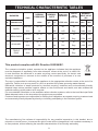
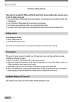
GUIDE FOR INSTALLATION AND USE
GB - Cooking Hob
COD. 208248 - REV0 - 30.08.2007
Dear Customer,
You have just acquired a FAGOR hob and we would like to thank you. Our research teams have created
a new generation of appliances for you. Their quality, design, features and technological advances make
them exceptional products and reveal our unique know-how. In the line of FAGOR products, you will also
find a wide range of ovens, microwave ovens, ventilation hoods, dishwashers, and refrigerators, all of
which can be integrated and all of which can be coordinated with your new FAGOR hob.
FAGOR
GENERAL NOTICE
We invite you to read this instruction booklet carefully, before installing and using the equipment.
It is very important that you keep this booklet together with the equipment for any future
consultation.
If this equipment should be sold or transferred to another person, make sure that the new
user receives the booklet, so that he can learn how to operate the appliance and read the
corresponding notice.
This is a Class 3 appliance.
This appliance complies with the following Directives:
EEC 90/396 (Gas)
2006/95/CE (Low Voltage)
EEC 89/336 (Electromagnetic Compatibility)
EEC 89/109 (Contact with foods)
- The installation must be carried out by experienced and qualified personnel, in conformity with the
regulations in force.
- This equipment has been designed to be used by adults.
- Therefore, make sure that children do not go near the equipment to play with it.
- While the appliance is running, watch the children and make sure they neither stay near the equipment,
nor touch the surfaces that have not cooled down completely.
- Before powering the equipment, check that it is properly adjusted for the type of gas at disposal (see the
“installation” paragraph).
- Before carrying out the maintenance or cleaning the equipment, cut power supply off and make it cool
down.
- Make sure that air circulates around the gas equipment. Insufficient ventilation produces a lack of oxygen.
- In case of an intense or prolonged use of the equipment, it may be necessary to improve aeration, for
example by opening a window or increasing the mechanical suction power, if it exists.
- The products of combustion must be discharged outside through a suction hood or an electric fan (see the
“installation” paragraph).
- For any possible operation or modification, apply to an authorized Technical Assistance Centre and
demand original spare parts.
WARNING:
If the appliance is equipped with a glass cover, the latter may shatter if heated. Turn off all the
burners and wait a few minutes before closing the cover.
The product label, with the serial number, is sticked under the hob.
The manufacturer refuses all responsibility for possible damages to things or people, resulting
from a wrong installation or from an improper, incorrect or unreasonable use of this equipment.
2
INSTRUCTIONS FOR THE USER
It is necessary that all the operations regarding the installation, adjustment and
adaptation to the type of gas available are carried out by qualified personnel, in
conformity with the regulations in force.
The specific instructions are described in the booklet section intended for the
installer.
USING THE BURNERS
these substances can catch fire when overheated.
- Do not use sprays near the appliance in operation.
- Do not place unstable or deformed pots on the burner, so
as to prevent them from overturning or overflowing.
- Make sure that pot handles are placed properly.
- When the burner is started up, check that the flameis
regular and, before taking pots away, always lowerthe
flame or put it out.
The symbols silk-screen printed on the side of the knob
indicate the correspondence between the knob and the
burner.
Automatic start-up with valves
Turn the corresponding knob anticlockwise up to the
maximum position (large flame, fig. 1) and press the knob.
Once the burner has been started up, keep the knob
pressed for about 6 seconds.
CLEANING
Before any operation, disconnect the appliance from the
electric grid.
It is advisable to clean the appliance when it is cold.
Using the burners
In order to obtain the maximum yield without waste of
gas, it is important that the diameter of the pot is suitable
for the burner potential (see the following table), so as to
avoid that the flame goes out of the pot bottom (fig. 2).
Use the maximum capacity to quickly make the liquids
reach the boiling temperature, and the reduced capacity
to heat food or maintain boiling. All of the operating
positions must be chosen between the maximum and the
minimum ones, never between the minimum position and
the closing point.
Use the maximum capacity to quickly make the liquids
reach the boiling temperature, and the reduced capacity
to heat food or maintain boiling. All of the operating
positions must be chosen between the maximum and the
minimum ones, never between the minimum position and
the closing point.
The gas supply can be interrupted by turning the knob
clockwise up to the closing position.
If there is no power supply, it is possible to light the
burners with matches, setting the knob to the start-up
point (large flame, fig. 1).
BURNERS
Power W
Enamelled parts
The enamelled parts must be washed with a sponge and
soapy water or with a light detergent.
Do not use abrasive or corrosive products.
Do not leave substances, such as lemon or tomato juice,
salt water, vinegar, coffee and milk on the enamelled
surfaces for a long time.
Stainless steel parts
Stainless steel can be stained if it remains in contact with
highly calcareous water or aggressive detergents for an
extended period of time.
The stainless steel parts should also be cleaned with
soapy water and then dried with a soft cloth.
Burners and racks
These parts can be removed to make cleaning easier.
The burners must be washed with a sponge and soapy
water or with a light detergent, wiped well and placed in
their housing perfectly. Make sure that the flame-dividing
ducts are not clogged.
Check that the feeler of the safety valve and the start-up
electrode are always perfectly cleaned, so as to ensure
an optimum operation.
The racks can be washed in the dishwasher.
Ø of pots
Auxiliary
1000
10 - 14 cm
Semi-rapid
1750
16 - 18 cm
Rapid
3000
20 - 22 cm
Triple crown
3800
24 - 26 cm
Gas taps
The possible lubrication of the taps must be carried out by
specialized personnel, exclusively.
In case of hardening or malfunctions in the gas taps,
apply to the Customer Service.
Notice
- When the equipment is not working, always check that
the knobs are in the closing position (see fig.1).
- If the flame should blow out accidentally, the safety
valve will automatically stop the gas supply, after a few
seconds. To restore operation, set the knob to the lighting
point (large flame, fig. 1) and press.
- While cooking with fat or oil, pay the utmost attention as
3
INSTRUCTIONS FOR THE INSTALLER
IMPORTANT NOTICE:
THE OPERATIONS INDICATED BELOW MUST BE FOLLOWED BY QUALIFIED PERSONNEL
EXCLUSIVELY, IN CONFORMITY WITH THE REGULATIONS IN FORCE.
THE MANUFACTURING FIRM REFUSES ALL RESPONSIBILITY FOR DAMAGES TO PEOPLE,
ANIMALS OR THINGS, RESULTING FROM THE FAILURE TO COMPLY WITH SUCH PROVISIONS.
INSTALLATION
Fastening the top
Every cook-top is equipped with a special washer.
A set of hooks is also supplied for mounting the
cook-top.
Depending on the type of mounting surface, the
suitable type of mounting hook is supplied (hook A
or hook B).
For the installation proceed as follows:
- Remove the racks and burners from the top.
- Turn the appliance upside down and lay the
washer S along the external border (fig. 5).
- Introduce and place the cook-top in the hole made
in the piece of furniture, then block it with the V
screws of the fastening hooks G (fig.6 / 6A).
Installing the top
The appliance is designed to be embedded into
heat-resistant pieces of furniture.
The walls of the pieces of furniture must resist a
temperature of 75°C besides the room one.
The equipment must not be installed near
inflammable materials, such as curtains, cloths,etc.
Make a hole in the top of the piece of furniture, with
the dimensions indicated in fig. 3, at a distance of
at least 50 mm from the appliance border to the
adjacent walls.
MODEL
L (mm)
P (mm)
5FI-4GLSX
5FI-4GLSTX
5FI-5GLSTX
560
480 - 490 (*)
5FI-95GLSTX
820
480 - 490 (*)
Installation room
This appliance is not provided with a device for
exhausting the products of combustion.
The room containing this hotplate should have an
air supply in accordance with BS 5440: Part 2:
1989.
(*) Necessary size for the installation with
cover.
- All rooms require an openable window, or
equivalent and some rooms will require a
permanent vent a well.
- For room volumes up to 5 m 3 an air vent of
100cm2 is required.
- For room volumes between 5 m3 and 10 m3 an air
vent of 50 cm2 is required.
- If the room is greater than 5 m3 and has a door
that opens directly to the outside, then no air vent
is required.
Any possible wall unit over the cook-top must be
placed at a distance of at least 760 mm from the
top.
It is advisable to isolate the appliance from the
piece of furniture below with a separator, leaving a
depression space of at least 10 mm (fig. 4).
If the hob is going to be installed on the top of an
oven, precautions must be taken to guarantee an
installation in accordance with current accident
prevention standards. Pay particular attention to
the position of the electric cable and gas pipe: they
must not touch any hot parts of the oven.
Moreover, if the hob is going to be installed on
the top of a built in oven without forced cooling
ventilation, proper air vents must be installed to
guarantee an adequate ventilation, with the lower
air entering with a cross section of at least 200cm2,
and the higher air exiting with a cross section of at
least 60 cm2.
If there are other fuel burning appliances in the
same room BS 5440: Part 2:1989 should be
consulted to determine the air vent requirements.
4
INSTRUCTIONS FOR THE INSTALLER
Gas connection
Make sure that the appliance is adjusted for
the gas type available (see the label under the
appliance). Follow the instructions indicated in the
chapter “gas transformations and adjustments” for
the possible adaptation to different gases.
The appliance must be connected to the gas
system by means of stiff metal pipes or flexible
steel pipes having continuous walls, in compliance
with the regulations in force.
Some models are equipped with both cylindrical A
and conical B connectors for gas supply (fig. 7).
Please select the type which is correct for the
supply concerned.
The connection must not stress the gas ramp.
Once the installation is over, check the
connection seal with a soapy solution.
Adjusting the burners
The lowest flame point must always be properly
adjusted and the flame must remain on even if
there is an abrupt shift from the maximum to the
minimum position.
If this is not so, it is necessary to adjust the lowest
flame point as follows:
- start the burner up
- turn the tap up to the minimum position (small
flame)
- remove the knob from the tap rod
- introduce a flat-tip screwdriver C in the hole F of
the tap (fig. 9) and turn the by-pass screw up to a
proper adjustment of the lowest flame point.
Electric connection
The connection to the electric grid must be carried
out by qualified personnel and in conformity with
the regulations in force.
The voltage of the electric system must correspond
to the value indicated in the label under the
appliance. Make sure that the electric system is
provided with an effective ground connction in
compliance with the regulations and provisions of
the law. Grounding is compulsory.
MAINTENANCE
As regards G30 gas burners, the by-pass screw
must be tightened completely.
Replacing the power supply cable
If the power supply cable should be replaced,
it is necessary to use a cable with a section of
3x0.75mm2, type HO5VV-F or H05RR-F, complying
with the regulations in force.
The connection to the terminal board must be
effected as shown in fig. 10 - 10/A:
brown cable L
blue cable N
green-yellow cable
GAS TRANSFORMATIONS AND ADJUSTMENTS
Replacing the nozzles
If the equipment is adjusted for a type of gas that
is different from the one available, it is necessary
to replace the burner nozzles.
The choice of the nozzles to replace must be
made according to the table of the “technical
characteristics” as enclosed.
Act as follows:
- Remove the racks and burners.
- By means of a straight spanner L, unscrew
the nozzle U (fig.8) and substitute it with the
corresponding one.
- Tighten the nozzle strongly.
5
(phase)
(neutral)
(ground)
Close
Maximun
Minimum
1
2
3
4
5
6A
7
6
8
10
9
6
10/A
5FI-4GLSX
5FI-4GLSTX
5FI-5GLSTX
5FI-95GLSTX
1 Rapid burner
2 Semi-rapid burner
3 Auxiliary burner
4 Triple ring burner
8 Control knob for burner
3000 W
1750 W
1000 W
3800 W
7
TECHNICAL CHARACTERISTIC TABLES
INJECTOR
DIAMETER
TAPE BY
PASS
DIAMETER
mbar
g/h
L/h
1/100 mm
1/100 mm
Max.
Min.
G30-G31
28 - 37
225
-
85
42
3000
950
G20
20
-
290
115Y
Reg.
3000
950
G30-G31
28 - 37
126
-
65
31
1750
600
G20
20
-
165
97Z
Reg.
1750
600
G30-31
28 - 37
71
-
50
27
1000
450
G20
20
-
99
72X
Reg.
1000
450
G30-G31
28 - 37
278
-
98
60
3800
2100
G20
20
-
367
135K
Reg.
3800
2100
GAS
N°
DESCRIPTION
1
RAPID
2
SEMI-RAPID
3
AUXILIARY
4
TRIPLE
RING
NOMINAL
HEAT INPUT
(W)
NOMINAL
RATE
BURNERS
NORMAL
PRESSURE
This product complies with EU Directive 2002/96/EC.
The crossed-out dustbin symbol reported on the appliance indicates that the appliance
must be disposed of separately from other domestic refuse at the end of its useful life.
It must therefore be delivered to a waste recycling centre specifically for electric and
electronic equipment or returned to the retailer at the moment of purchase of a new
equivalent appliance.
The user is responsible for delivering the appliance to the appropriate collection centre at the end of its
useful life, Failure to do so may result in a fine, as provided for by laws governing waste disposal.
Differential collection of waste products for eventual recycling, treatment and environmentally friendly
disposal helps reduce possible negative effects on the environment and health, and also enables the
materials making up the product to be recycled.
For more detailed information on the available refuse collection systems, refer to the local Municipal Solid
Waste disposal centre or the shop where the product was purchased.
Producers and importers are responsible for fulfilling their obligations as regards recycling, treatment and
environmentally friendly disposal by directly or indirectly participating in the collection system.
The manufacturing firm refuses all responsibility for any possible imprecision in this booklet, due to
misprints or clerical errors. It reserves the right to make all the changes that it will consider necessary in
its own products, without effecting the essential characteristics of functionality and safety.
8