1
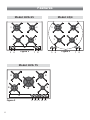
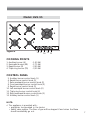
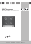
Gas on glass cooktops
4Q4
HVG 65
HVG 75
HVG 95
GB
Users Operating Instructions
Installation instructions
Before operating this hob,
please read these instructions carefully
Dear Customer
Thank you for choosing one of our appliances, carefully designed and built by
our specialist staff and thoroughly tested to satisfy your cooking requirements.
We suggest that you read this Instruction Booklet so that you will understand
fully how to operate your appliance.
Please keep the booklet handy. You may wish to refer to it at a later date.
CDA
Declaration of
CE
conformity
✓ This hob (Class 3) has been designed for use only as a cooking appliance. Any
other use (e.g. heating rooms) should be considered incorrect and therefore
dangerous.
✓ This hob has been designed, constructed and put on to the market in conformity with:
- Safety requirements of EU Directive "Gas" 90/396/EEC;
- Safety requirements of EU Directive "Low Voltage" 2006/95/EC;
- Protection requirements of EU Directive "EMC" 89/336/EEC;
- Requirements of EU Directive 93/68/EEC.
GB
These instructions are only valid for those countries whose identification symbol appears on the cover of the instruction booklet and on the product data
plate.
Important:
This appliance is designed and manufactured solely for the cooking of domestic
(household) food and is not suitable for any non domestic application and therefore should not be used in a commercial environment.
The appliance guarantee will be void if the appliance is used within a non domestic environment i.e. a semi commercial, commercial or communal environment.
2
CONTENTS
Page Number
Before using for the first time . . . . . . . . . . . . . . . . . . . . . . . . . . . . . . . . . . 4
Important safeguards & recommendations . . . . . . . . . . . . . . . . . . . . . . . . 5
Features . . . . . . . . . . . . . . . . . . . . . . . . . . . . . . . . . . . . . . . . . . . . . . . . . 6
Use of the hob . . . . . . . . . . . . . . . . . . . . . . . . . . . . . . . . . . . . . . . . . . . . 8
Gas burners . . . . . . . . . . . . . . . . . . . . . . . . . . . . . . . . . . . . . . . . . . . . . . . . . . . . 8
Lighting the burners . . . . . . . . . . . . . . . . . . . . . . . . . . . . . . . . . . . . . . . . . . . . . . 9
Choice of burner . . . . . . . . . . . . . . . . . . . . . . . . . . . . . . . . . . . . . . . . . . . . . . . 10
Correct use of triple-ring burner . . . . . . . . . . . . . . . . . . . . . . . . . . . . . . . . . . . . 11
Correct use of the burners . . . . . . . . . . . . . . . . . . . . . . . . . . . . . . . . . . . . . . . . 12
Cleaning and Maintenance . . . . . . . . . . . . . . . . . . . . . . . . . . . . . . . . . . . 13
Hob surfaces . . . . . . . . . . . . . . . . . . . . . . . . . . . . . . . . . . . . . . . . . . . . . . . . . . 13
Burners and grids . . . . . . . . . . . . . . . . . . . . . . . . . . . . . . . . . . . . . . . . . . . . . . . 15
Correct positioning of the burners . . . . . . . . . . . . . . . . . . . . . . . . . . . . . . . . . . 16
Tips for installation
Location . . . . . . . . . . . . . . . . . . . . . . . . . . . . . . . . . . . . . . . . . . . . . . . . . 19
Technical information for the installer . . . . . . . . . . . . . . . . . . . . . . . . . . 20
Fastening the cooktop . . . . . . . . . . . . . . . . . . . . . . . . . . . . . . . . . . . . . . 22
Ventilation requirements . . . . . . . . . . . . . . . . . . . . . . . . . . . . . . . . . . . . . 23
Gas supply requirements . . . . . . . . . . . . . . . . . . . . . . . . . . . . . . . . . . . . 24
Gas connection . . . . . . . . . . . . . . . . . . . . . . . . . . . . . . . . . . . . . . . . . . . 25
Conversion to Natural Gas or LPG . . . . . . . . . . . . . . . . . . . . . . . . . . . . . . 27
Minimum burner setting adjustment . . . . . . . . . . . . . . . . . . . . . . . . . . . . 29
Lubrication of the gas taps . . . . . . . . . . . . . . . . . . . . . . . . . . . . . . . . . . . 29
Electrical connection . . . . . . . . . . . . . . . . . . . . . . . . . . . . . . . . . . . . . . . . 30
Appliance servicing . . . . . . . . . . . . . . . . . . . . . . . . . . . . . . . . . . . . . . . . . 32
Guarantee . . . . . . . . . . . . . . . . . . . . . . . . . . . . . . . . . . . . . . . . . . . . . . . 33
3
BEFORE USING FOR THE FIRST TIME
• Read the instructions carefully before installing and using the appliance
• After unpacking the appliance, make sure it is not damaged. In case of doubt, do not
use the appliance and contact your supplier or a qualified engineer.
• Remove all packaging and do not leave the packing material (plastic bags, polystyrene, bands etc ) in easy reach of children as they may cause serious injury. The
packaging materials are recyclable.
• The appliance should be installed and all the gas/electrical connections made by a
qualified engineer in compliance with local regulations in force and following the
manufacturer’s instructions.
• Do not attempt to modify the technical properties of the appliance, as it may become
dangerous to use.
4
IMPORTANT SAFEGUARDS & RECOMMENDATIONS
• Do not carry out any cleaning or maintenance without first disconnecting the appliance from the electrical supply.
• During and after use of the hob, certain parts will become very hot. Do not touch
hot parts.
• After use always ensure that the control knobs are in the “●” OFF position.
• Young children should be supervised to ensure that they do not play with the appliance.
• Keep children away from the hob during use.
• The appliance is not intended for use by young children or infirm persons unless they
have been adequately supervised by a responsible person to ensure that they can
use the appliance safely.
• Do not allow young children or infirm persons to use the appliance without your
supervision.
• WARNING
When correctly installed, your product meets all safety requirements laid down for
this type of product category. However special care should be taken around the
underneath of the appliance as this area is not designed or intended to be touched
and may contain sharp or rough edges, that may cause injury.
• Fire Risk! Do not leave inflammable materials on the hob top.
• Make sure that electrical cords connecting other appliances in the proximity cannot
come in to contact with the hob top.
• Do not scratch the hob with sharp objects. Don’t use the hob as a work surface.
• Do not allow heavy or sharp objects to drop on the glass surface.
• Do not use the hob if the glass surface is broken or cracked in any way.
Please disconnect the hob from the mains and contact the After-Sales
Service
• Never use a damaged appliance. Get it checked or repaired: “see appliance servicing”.
• When the appliance is not being used, it is advisable to keep the gas tap closed.
• Regular lubrication of the gas taps must only be carried out by qualified engineers.
Contact Service in case of problems with the operation of the gas taps.
• Before disposing of an unwanted appliance, it is recommended that it is made inoperative and that all potentially hazardous parts are made harmless.
• If the power supply cable is damaged, it must be replaced only by an
authorised service agent in order to avoid a hazard.
CAUTION:
Gas hobs produce heat and humidity in the environment in which they are installed.
Ensure that the cooking area is well ventilated by opening the natural ventilation grilles
or by installing an extractor hood connected to an outlet duct.
CAUTION:
If the hob is used for a prolonged time it may be necessary to provide further ventilation
by opening a window or by increasing the suction power of the extractor hood (if fitted).
5
Features
Model: 4Q4
Model: HVG 65
3
1
5
3
2
6
1
2
Figure 1
7
5
8
Model: HVG 75
2
3
Figure 3
6
2
4
2
1
9 10 11 12 13
6
2
Figure 2
7
8
Model: HVG 95
2
2
4
3
Figure 4
1
13 9 10 12 11
COOKING POINTS
1. Auxiliary burner (A)
2. Semirapid burner (SR)
3. Rapid burner (R)
4. Triple ring burner (TR)
- 1,00 kW
- 1,75 kW
- 3,00 kW
- 3,50 kW
CONTROL PANEL
5. Auxiliary burner control knob (1)
6. Rapid burner control knob (3)
7. Rear semirapid burner control knob (2)
8. Front semirapid burner control knob (2)
9. Rapid burner control knob (3)
10. Left semirapid burner control knob (2)
11. Triple ring burner control knob (4)
12. Right semirapid burner control knob (2)
13. Auxiliary burner control knob (1)
NOTE:
✓ The appliance is provided with:
• gas-lighter incorporated in the knobs
• safety valve system. The flow of gas will be stopped if and when the flame
should accidentally go out.
7
Use of the Hob
GAS BURNERS
Gas flow to the burners is adjusted by turning the knob illustrated in fig. 5 which controls the safety valves.
Turning the knob so that the indicator line points to the symbols printed on the panel
achieves the following functions:
✓ full circle
●
=
closed valve
✓ symbol
=
maximum aperture or flow
✓ symbol
=
minimum aperture or flow
The maximum aperture position permits rapid boiling of liquids, whereas the minimum
aperture position allows slower warming of food or maintaining boiling conditions of
liquids.
To reduce the gas flow to minimum, rotate the knob further anti-clockwise to point
the indicator towards the small flame symbol.
Other intermediate operating adjustments can be achieved by positioning the indicator
between the maximum and minimum aperture positions, not between the maximum
aperture and closed positions.
N.B. When the hob is not being used, set the gas knobs to their closed positions and also close the cock valve on the gas bottle or the main gas supply
line.
Figure 5
8
LIGHTING THE BURNERS
In order to light the burner, you must:
1 – Press in the corresponding knob and turn counter-clockwise to the full flame
position marked by the
symbol (fig. 6) and hold the knob in until the
flame has been lit.
In the case of a mains failure light the burner with a match or lighted taper.
2 – Wait about ten seconds after the gas lighting before releasing the knob (starting
time for the valve).
3 – Adjust the gas valve to the desired power.
Important
If the burner flame should go out for some reason, the safety valve will automatically
stop the gas flow.
To re-light the burner, return the knob to the closed ● position, wait for at least 1
minute and then repeat the lighting procedure.
If your local gas supply makes it difficult to light the burner with the knob set to maximum, set the knob to minimum and repeat the operation.
Figure 6
9
CHOICE OF BURNER
The burner must be choosen according to the diameter of the pans and energy
required.
Figure 7
PAN DIAMETER
BURNER
MINIMUM
Auxiliary
12 cm
14 cm
Semirapid
16 cm
(1)
Rapid
24 cm
Triple-ring
26 cm
Woks (2)
MAXIMUM
20
- 24 cm
26 cm
28 cm
max 36 cm
do not use pans with concave or convex bases
(1) Front right Semirapid burner of models HVG 65, 4Q 4 only.
(2) Models with triple-ring and with wok pan adapter (the wok pan adapter is available as an
accessory at extra cost): wok pans have to be used only with the special grille fitted (see correct use of triple-ring burner).
Saucepans with handles which are excessively heavy, in relationship to the weight
of the pan, are safer as they are less likely to tip. Pans which are positioned
centrally on burners are more stable than those which are offset.
It is far safer to position the pan handles in such a way that they cannot be
accidentally knocked.
When deep fat frying fill the pan only one third full of oil.
DO NOT cover the pan with a lid and DO NOT leave the pan unattended.
In the unfortunate event of a fire, leave the pan where it is and turn off all
controls.
Place a damp cloth or correct fitting lid over the pan to smother the flames.
DO NOT use water on the fire.
Leave the pan to cool for at least 30 minutes.
10
CORRECT USE OF TRIPLE-RING BURNER
✓ The flat-bottomed pans are to be placed directly onto the pan-support.
✓ To use the WOK you need to place the proper stand (available as an accessory at
extra cost) in order to avoid any faulty operation of the triple-ring burner (Figs. 8a
- 8b).
IMPORTANT:
The special grille for wok pans (available as an accessory at extra cost) (fig. 8b) MUST
BE PLACED ONLY over the pan-rest for the triple-ring burner.
Figure 8a
Figure 8b
WRONG
CORRECT
11
Figure 9
12
Cleaning and Maintenance
GENERAL TIPS
✓
✓
✓
✓
✓
Before cleaning the hob switch it off and wait for it to cool down.
Clean with a cloth, hot water and soap or liquid detergent.
Do not use products which are abrasive, corrosive or chlorine based.
Do not use steel pads.
Do not leave acid or alkaline substances (vinegar, salt, lemon juice, etc.) on the
hob.
✓ Do not use steam jet cleaners because the humidity could infiltrate into
the appliance making it dangerous.
✓ WARNING: When correctly installed, your product meets all safety requirements
laid down for this type of product category. However special care should be taken
around the underneath of the appliance as this area is not designed or intended
to be touched and may contain sharp or rough edges, that may cause injury.
GLASS SURFACE
✓ Remove spillages and other types of incrustations by using only specific products
which do not contain abrasives or chlorine-based acids.
✓ If you use a detergent, please make sure that it is not abrasive or scouring. Abrasive
or scouring powders can damage the glass surface of the hob.
✓ All traces of the cleaner must be removed with a damp cloth.
✓ Dust or food particles can be removed with a damp cloth.
✓ Dust, fat and liquids from food that has boiled over must be removed as soon as
✓
✓
✓
✓
possible.
If they are allowed to harden they become increasingly difficult to remove. This is
especially true in the case of sugar/syrup mixtures which could permanently
damage the surface of the hob if left to burn on it.
Avoid using a knife or other sharp utensil as these may damage the glass surface.
Do not use steel wool or an abrasive sponge which could scratch the surface
permanently.
Do not put articles on the hob which can melt: i.e plastic, aluminium foil, sugar,
sugar syrup mixtures etc.
Do not use harsh abrasive cleaners or sharp metal scrapers to clean the
glass since they can scratch the surface, which may result in shattering
of the glass.
13
ENAMELLED PARTS
✓ All the enamelled parts must be washed only with a sponge with soapy water or
other non-abrasive products.
✓ Dry preferably with a soft cloth.
✓ If acid substances such as lemon juice, tomato conserve, vinegar etc. are left on
the enamel for a long time they will etch it, making it opaque.
STAINLESS STEEL SURFACES (some models only)
✓ Stainless steel parts should be rinsed with water and dried with a microfibre or
soft cloth.
✓ For persistent dirt, use specific non-abrasive products available commercially or a
little hot vinegar.
✓ Note: regular use will cause discolouring around the burners, because of the high
flame temperature.
GAS TAPS
✓ Regular lubrication of the gas taps must only be performed by specialised engineers.
✓ If the gas taps are not working properly call the After-Sales Service.
CONTROL KNOBS
✓ The control knobs may be removed for cleaning but care should be taken not to
damage the seal.
14
BURNERS AND GRIDS
✓ These parts can be removed and cleaned with appropriate products.
✓ After cleaning, the burners and their flame spreaders must be well dried and correct-
ly replaced.
✓ It is very important to check that the burner flame spreader and the cap have been
correctly positioned. Failure to do so can cause serious problems.
✓ Check that the electrode “S” (figs. 11 and 14) is always clean to ensure trouble-free
sparking.
✓ Check that the probe “T” (figs. 11 and 14) next to each burner is always clean to
ensure correct operation of the safety valves.
✓ Both the probe and ignition plug must be very carefully cleaned.
✓ Note: To avoid damage to the electric ignition do not use it when the
burners are not in place.
IMPORTANT WARNING
NEVER unscrew the burner plate fixing screws (fig. 10).
The burner plates can be removed ONLY by an authorised service agent.
Damage to the appliance will occur if not observing this condition and
this may result in serious injury to the user.
The manufacturer declines every responsibility for any inconvenience
resulting from the inobservance of this condition.
Figure 10
15
CORRECT POSITIONING OF THE AUXILIARY, SEMIRAPID AND
RAPID BURNERS
✓ It is very important to check that the
Figure 12
burner flame spreader “F” and the
cap “C” have been correctly positioned (see figs. 11 and 12). They
shall be level and must not rotate.
Failure to do so can cause serious
problems.
✓ The pan supports shall be correctly
positioned as indicated in fig. 13.
The pan supports shall be level and
must not rotate.
Models with triple-ring burner: be
sure not to fit the triple-ring burner
pan support on the auxiliary, semirapid or rapid burners. The triple-ring
burner pan support IS ONLY to be
used on the triple-ring burner.
Figure 11
Figure 13
C
F
Ignitor "S"
16
Flame failure
probe "T"
MODELS WITH TRIPLE RING BURNER CORRECT POSITIONING OF THE TRIPLE RING BURNER
The triple ring burner must be correctly
positioned (see fig. 14); the burner ribs
must be fitted in their housing as
shown by the arrow.
The burner correctly positioned must
not rotate (fig. 15).
Then position the cap “A” and the ring
“B” (figs. 15 - 16). They shall be level.
Figure 16
✓ The pan support shall be correctly
positioned as indicated in fig. 17.
The pan support shall be level and
must not rotate.
Be sure not to fit the auxiliary, semirapid or rapid burner pan support on
the triple-ring burner. The auxiliary,
semirapid or rapid burner pan support IS ONLY to be used on the auxiliary, semirapid or rapid burners.
Figure 14
Figure 17
Ignitor "S"
Flame
failure
probe "T"
Figure 15
A
B
17
Tips
for
installation
18
Location
✓ The appliance may be installed in a kitchen, Kitchen/diner or a bed sitting room, but
not in a room or space containing a bath or a shower.
✓ The appliance must not be installed in a bed-sitting room of less than 20 m3.
✓ The appliance is designed and approved for domestic use only and should not be
installed in a commercial, semi commercial or communal environment.
✓ Your product will not be guaranteed if installed in any of the above environments
and could affect any third party or public liability insurances you may have.
✓ This hob should only be installed by a qualified installer.
Failure to observe this rule leads to cancellation of the guarantee.
✓ The appliance must be installed correctly, in compliance with the regulations in force
and following the manufacturer's instructions.
✓ Any repair or maintenance must be performed with the appliance switched off.
✓ These hobs are designed to be fitted into 600 mm deep kitchen units.
✓ These appliances have been designed and manufactured to be fitted into heat-resis-
tant units.
✓ The walls of the units must be capable of resisting temperatures of 75 °C above
room temperature.
✓ We would point out that the adhesive which bonds the plastic laminate to the furni-
ture must withstand temperatures not less than 150 °C to avoid elamination.
✓ Avoid installation near inflammable materials (e.g. curtains).
19
TECHNICAL INFORMATION FOR THE INSTALLER
In order to install the cooktop into the kitchen fixture, a hole with the dimensions
shown in fig. 19 has to be made, bearing in mind the following:
✓ Within the unit, between the bottom of the cooktop and the upper surface of a
shelf there must be a clearance of at least 30 mm.
It is absolutely essential that you place a separator between the base of the cooktop
and the built-in unit or the oven;
✓ The cooktop must be kept no less than 200 mm away from any side wall (fig. 18).
✓ There must be a distance of at least 60 mm between the back side of the cut-out
and the back of the countertop.
✓ There must be a distance of at least 650 mm between the hob and any wall cup-
board or extractor hood positioned immediately above (see fig. 18).
✓ If the hob is installed over a built-in oven, the built-in oven shall be provided with
cooling fan.
The two appliances shall be connected to the gas/electric supply with independent
connections.
200 m
m min
20
650 mm
450 mm
Figure 18
500 m
m
Figure 19
HVG 75
HVG 65 - 4Q4
585
715
0
51
(2)
60
54 (1)
48
48
0
0
54 (1)
60
(2)
0
51
680
560
HVG 95
869
0
48
0
60
54 (1)
(2)
51
840
54 mm from top of countertop
at least 60 mm between the back side of the cut-out and the back of the countertop.
INSTALLING THE
SEPARATOR BELOW THE
BASE OF THE COOKTOP
It is recommended that a 30 mm clearance be left between to base of the
cooktop and the separator.
The separator shall be heat resistant,
made of low thermal conductivity
material and shall be removable with
the use of a tool for installation and service.
Figure 20
Clearance
Separator
30 mm
(1):
(2):
Space for
connections
21
FASTENING THE COOKTOP
Each cooktop is provided with an installation kit including brackets and screws for fastening the cooktop to benches from 30 to 40 mm thick.The kit includes two "F" type
brackets (for the front of the cooktop), two "R" type brackets (for the rear of the cooktop) and four self-threading screws "S" (figs. 21, 22a and 22b).
✓ Cut the unit according to the dimensions in fig. 19.
✓ Turn the hob upside down and rest the glass side on a soft surface.
✓ Spread the seal "G" around the edge of the hob (fig. 21).
✓ Fasten the brackets "F" and "R" to the appropriate socket holes, without tightening
the screws "S" for the moment. Make sure that the tabs are mounted correctly, as
shown. Rotate the tabs so that the cooktop can be put into the cutout.
✓ Put the cooktop into the cutout and
Figure 21
position it correctly.
✓ Put the brackets "F" and "R" into
place; tooth "A" of the brackets
should go into the hole (Figs. 22a
and 22b).
G
✓ Tighten screws "S" until the cooktop
is completely secured to the bench.
✓ Using a sharp cutter or trimmer knife,
trim the excess sealing material
around the edge of the cooktop.
Take care not to damage the workbench.
REAR FIXING BRACKETS
FRONT FIXING BRACKETS
22
A
3 cm
min
S
3 cm
min
A
R
3 cm
Figure 22b
3 cm
4 cm
Figure 22a
S
F
4 cm
Adhesive side
G
Ventilation requirements
✓ The appliance should be installed into a room or space with an air supply in accor-
dance with BS 5440-2: 2000.
✓ For rooms with a volume of less than 5 m3 - permanent ventilation of 100 cm2 free
area will be required.
✓ For rooms with a volume of between 5 m3 and 10 m3 a permanent ventilation of
50 cm2 free area will be required unless the room has a door which opens directly to
the outside air in which case no permanent ventilation is required.
✓ For rooms with a volume greater than 10 m3 - no permanent ventilation is required.
NB. Regardless of room size, all rooms containing the appliance must
have direct access to the outside air via an openable window or
equivalent.
✓ Where there are other fuel burning appliances in the same room, BS 5440-2: 2000
should be consulted to determine the correct amount of free area ventilation requirements.
✓ The above requirements allow also for use of a gas oven and grill but if there are
other gas burning appliances in the same room, consult a qualified engineer.
23
Gas supply requirements
IMPORTANT NOTE
This appliance is supplied for use on NATURAL GAS or LPG (check the gas regulation
label attached on the appliance).
✓ Appliances supplied for use on NATURAL GAS: they are adjusted for this gas only
and cannot be used on any other gas (LPG) without modification. The appliances
are manufactured for conversion to LPG.
✓ Appliances supplied for use on LPG: they are adjusted for this gas only and cannot
be used on any other gas (NATURAL GAS) without modification. The appliances are
manufactured for conversion to NATURAL GAS.
If the NATURAL GAS/LPG conversion kit is not supplied with the appliance this kit can
be purchased by contacting the After-Sales Service.
INSTALLATION & SERVICE REGULATIONS (UNITED KINGDOM)
It is a legal requirement that all gas appliances are Installed & Serviced by a competent
person in accordance with the current editions of the following Standards &
Regulations or those regulations appropriate to the geographical region in which
they are to be installed:
✓ Gas Safety (Installation & Use) Regulations
✓ Building Regulations
✓ British Standards
✓ Regulations for Electrical Installation
Installation and service of any gas product must be made by a suitably qualified
person competent on the type of product being installed or serviced and holding a
valid certificate of competence for the work being carried out. Currently the proof of
competence is the Accredited Certification Scheme (ACS) or S/NVQ that has been
aligned to the ACS.
It is also a requirement that all businesses or self employed installers are members of
a class of person approved by the Health and Safety Executive. Currently the only
body with such approval is CORGI.
Failure to install the appliance correctly could invalidate any manufacturers warranty
and lead to prosecution under the above quoted regulation.
24
Gas Connection
The installation of the gas appliance to Natural Gas or LP Gas must be carried out by a
C.O.R.G.I. registered installer. Installers shall take due account of the provisions of the
relevant British Standards Code of Practice, the Gas Safety Regulations and the
Building Standards (Scotland)(Consolidation) Regulations issued by the Scottish
Development Department.
INSTALLATION TO NATURAL GAS
Installation to Natural Gas must conform to the Code of Practice, etc.
The supply pressure for Natural Gas is 20 mbar.
The installation must conform to the relevant British Standards.
INSTALLATION TO LP GAS
When operating on Butane gas a supply pressure of 28-30 mbar is required. When
using Propane gas a supply pressure of 37 mbar is required.
The installation must conform to the relevant British Standards.
CDA are not legally able to provide any assistance in the installation of gas appliances
except to Corgi registered installers. Any Corgi registered fitter requiring help must provide name, address and registration number.
Information supplied will be validated before help is provided.
Warning: Only a C.O.R.G.I. registered installer, also with technical knowledge
of electricity should install the appliance. He should observe the Regulations
and Codes of Practice governing such installation of gas appliances.
Note: It is recommended that the gas connection to the appliance is installed
with a flexible connecting tube made to BS5386.
Notes:
✓ Flexible hoses can be used where the sited ambient temperature of the
hose does not exceed 70°C. These hoses must be manufactured in
accordance with BS669 part 1 and be of the correct construction for the
type of gas being used.
✓ Gas hoses designed for natural gas MUST NOT be used for supplying LPG
gas (LPG gas hoses can be identified by a either a red band or stripe on
the rubber outer coating of the hose).
The hose should not be crushed or trapped or be in contact with sharp
or abrasive edges.
25
GAS CONNECTOR
GB
Cat: II 2H3+
The fitting (fig. 23) is made up of:
✓ 1 nut “A”
✓ 1 elbow fitting “C”
✓ gasket “F”
CONNECTION TO THE GAS SUPPLY
✓ Be careful when flexible pipes are used that they do not come into contact with
moving parts.
✓ To maintain the thickness of 3 cm, the hob is fitted with a channel to contain the
connection pipe.
✓ The gas inlet union can be turned in the direction required after the elbow fitting
“C” and nut “A” connection (figure 23) has been slackened (Fig. 24).
✓ Never put it in the horizontal or vertical position.
✓ Never attempt to turn the elbow “C” without having first slackened off the relative
lock nut “A”.
✓ The gasket “F” (fig. 23) guarantees the seal of the gas connection.
It is recommended that it be replaced whenever it shows even the slightest
deformation or imperfection.
✓ Using a suitable leak detection fluid solution (e.g. Rocol) check each gas
connection one at a time by brushing the solution over the connection.
The presence of bubbles will indicate a leak. If there is a leak, tighten
the fitting and then recheck for leaks.
IMPORTANT! Do not use a naked flame to test for leaks
Figure 23
1/2" G cylindrical
(ISO 228-1) male
C
Figure 24
1/2" G cylindrical
(ISO 228-1) female
F
A
1/2" G conical
(ISO 7-1) male
26
Conversion to Natural Gas or LPG
REPLACING THE BURNER INJECTORS
If the NATURAL GAS/LPG conversion kit is not supplied with the appliance this kit can
be purchased by contacting the After-Sales Service.
Choose the injectors to be replaced according to the table on next page.
The injector diameter, expressed in hundredths of a millimetre, is marked on the
injector body.
To replace the injectors proceed as follows:
✓ Remove the pan supports and the burners covers.
✓ Using a wrench, substitute the nozzle injectors “J” (Figs. 25 - 26) with those most
suitable for the kind of gas for which it is to be used.
The burners are made in such a way so as not to require regulation of the
primary air.
Figure 25
Figure 26
J
J
27
Table for the choice of the Injectors
GB
Cat:
II 2H3+
G30/G31
28-30/37 mbar
G 20
20 mbar
[Hs - kW]
[Hs - kW]
Ø injecteur
Ø injecteur
[1/100 mm]
[1/100 mm]
Auxiliary (A)
1,00
0,30
0,50
0,72 (X)
Semirapid (SR)
1,75
0,45
0,65
0,97 (Z)
BURNER
28
NOMINAL REDUCED
POWER
POWER
Rapid (R)
3,00
0,75
0,85
1,15 (Y)
Triple ring (TR)
3,50
1,50
0,95
1,35 (T)
MINIMUM BURNER SETTING ADJUSTMENT
Check whether the flame spreads to all
burner ports when the burner is lit with
the gas tap set to the minimum
position. If some ports do not light,
increase the minimum gas rate setting.
Figure 27
Check whether the burner remains lit
even when the gas tap is turned
quickly from the maximum to the
minimum position. If the burner does
not remain lit, increase the minimum
gas rate setting.
A
The adjustment is performed with the
burner lit, as follows:
✓ Turn the knob to the minimum
position.
✓ Remove the knob.
✓ Using a screwdriver turn screw "A"
until the flame setting is correct.
Normally for LPG, fully tighten the
adjustment screw.
Lubrication of the gas taps
The operations must be executed by a qualified technician.
IMPORTANT
All intervention regarding installation maintenance and conversion of the
appliance must be fulfilled with original factory parts.
The manufacturer declines any liability resulting from the non-compliance of
this obligation.
29
Electrical Connection
IMPORTANT: The appliance must be installed by a qualified technician according with the current local regulations and in compliance with the manufacturer instructions.
Incorrect installation may be dangerous and the manufacturer can not be
held responsible.
Warning! This appliance must be earthed
A properly earthed three pin plug (fused at 3 amps, to BS 1362 ASTA approved) must
be used. As the colours of the wires in the mains lead of this appliance may not
correspond with the coloured markings identifying the terminals in your plug, proceed
as follows.
The wire which is coloured GREEN & YELLOW must be connected to the terminal in
the plug which is marked with letter "E" or by the Earth symbol or coloured GREEN
& YELLOW.
The wire which is coloured BLUE must be connected to the terminal which is marked
with the letter "N" or coloured BLACK.
The wire which is coloured BROWN must be connected to the terminal which is
marked with the letter "L" or coloured RED.
Figure 28
Green &
Yellow
Earth
Blue Neutral
30
3 amp fuse
Brown Live
SECTION OF THE SUPPLY CABLE - TYPE “H05V2V2-F”
resistant to temperatures of 90°C
WARNING: If the power supply cable is damaged, it must be replaced only
by an authorised service agent in order to avoid a hazard.
230 VAC
50/60 Hz
3 x 0,75 mm2
✓ The electrical cable must be connected to the terminal board following the diagram
of Fig. 29.
The appliance must be earthed.
The manufacturer declines all responsibility for any problem caused by
failure to observe this rule.
Figure 29
230 V
L1 PE N(L2)
31
Appliance servicing
CDA provide a quality and effective after-sales service to cover all your
servicing needs.
Please attach your receipt to this page for safekeeping.
Please help us to help you by having the following information available
when booking a service-call:
1. Model type, make and model – see the product data plate.
2. Evidence of installation / purchase date
3. Retailer where appliance was purchased
4. Clear and concise details of the fault
5. Full address including postcode and any contact phone numbers
Contact telephone numbers
CDA Customer Care Department
• Telephone: 01949 862012
• Fax: 01949 862003
• Email: [email protected]
32
Guarantee
CDA appliances carry a five-year parts and a one-year labour guarantee.
CDA will repair or replace any defect or part attributable to faulty material or workmanship. Within the first year this will be free of both labour and parts charges. After the
first year and within five years, the parts will be supplied free of charge provided that
the repair is carried out by an agent authorised by CDA and the labour will be charged
at the commercial rate applicable at the time of repair.
The appliance must have been installed by a suitably qualified person and in accordance with the manufacturer’s instructions and current legislation. The guarantee does
not cover faults caused by the incorrect fitting of appliances.
Limit of Cover
• The guarantee does not cover cosmetic damage e.g. discolouration or oxidisation.
• Proof of purchase or installation date must be produced before a service-call will be
booked.
• The appliance must be used for domestic purposes only. Appliances used for commercial or professional purposes are not covered by the guarantee. Commercial warranty is available at extra cost.
• The appliance must not be modified or tampered with or repair attempted by any
unauthorised person.
• The guarantee does not cover damage caused in transit or by misuse, accident,
abuse or neglect.
• The guarantee does not cover routine maintenance.
• Use of parts not supplied or recommended by |C|D|A| will invalidate the warranty.
• Rubber seals, filters, removable glass parts, control knobs and buttons, fuses and
light bulbs will need replacing periodically and are not covered by the guarantee.
• Second-hand or reconditioned appliances are not covered by the guarantee.
The conditions under which this guarantee is offered are in addition to the statutory
rights of the domestic purchaser and these statutory rights are not affected by this
guarantee.
CDA reserve the right to change specification without prior notice.
33
34
35
Cod. 1103126 - ß4
Gas on glass cooktops
The
Group Ltd
Harby Road Langar Nottingham NG13 9HY UK
VAT No : 528 7168 19 Registered in England : 2621460
●
●
●
●
●