1
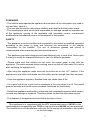
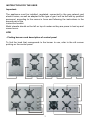
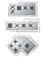
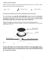
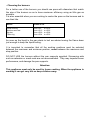
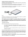
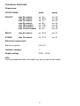
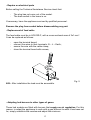
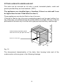
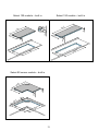
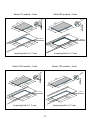
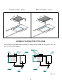
PISLG - inglese REV.06
INSTRUCTION FOR
INSTALLATION AND USE
HOBS
SELECT SERIES
built in
flush
WOLO SERIES
STARK SERIES
F.lli BARAZZA s.r.l.
31025 Sarano di Santa Lucia di Piave (TV)
Via Risorgimento, 14 – Tel +39 0438 62888 Fax +39 0438 64901
www.barazzasrl.it E-mail: [email protected]
DEAR CUSTOMER
F.lli Barazza S.r.l. in present in the household appliances market for over 40
years. Now it would thank you to have bought its appliance and it want to assure
you the quality of this product. The use of this appliance is not so difficult, but we
would invite you, before starting use it, to read careful the instructions below.
FOREWORD
- This booklet accompanies the appliance and contains all the information you need to
use and take care of it.
- The user should read its instructions carefully and keep the booklet within reach.
- The manufacturer shall not be held responsible for damage caused by improper use
of the appliance, moving of the appliance with unsuitable means, unauthorized
modifications and whatever else is not considered in this booklet.
SAFETY
- The appliance must be installed and connected to the mains by qualified personnel
according to the norms in force and following the instructions in the chapter
"Instructions for the installer", The use of protective glasses and gloves is
recommended when unpacking and during maintenance,
- This appliance has been designed and manufactured only to cook food. Never open
it unduly or modify its characteristics and or use it for different purposes.
- Please make sure that children do not touch the control panel or play with the
appliance. The parts exposed during cooking warm up and will stay warm for a while
after switching the appliance off.
- After using the appliance make sure that the knobs are on the “off ” position. If the
appliance is near other units make sure the cables are far enough from their hot parts.
- Clean the appliance regularly. Residual food can cause risks of fire.
- It is a good rule never to put food or containers in the oven when it is off. This would
produce humidity and could cause accidents if switched on involuntarily
- Should the appliance malfunction, authorized and competent personnel shall repair it
to avoid any damage or incidents. Therefore please contact the after sales service.
- The disposal of the appliance should follow the laws in force.
This appliance is in compliance with the EEC requirement rules n. 89/336 on the
electromagnetic compatibility and 73/23 on low tension and 90/396 on gas appliances.
The instructions in this booklet are valid only for the country of destination, see symbol
on the front page.
2
INSTRUCTION FOR THE USER
Important:
The appliance must be installed, regulated, connected to the gas network and
electric mains, as well as adapted to the type of gas it will be fed with by qualified
personnel, according to the norms in force and following the instructions in the
second part of the
instruction booklet.
Metal utensils should not be left on top of cooker as they are prone to heat up and
cause burns.
HOB
- Finding burners and description of control panel
To find the knob that corresponds to the burner to use, refer to the silk screen
printing on the control panel.
3
4
5
6
- How to use the burners
Next to each knob there is a symbol that shows which burner it refers to. Each
gas burner knob has the following symbols:
Stop
Maximum setting
Minimum setting
The burner should be turned on before putting the pan on the rung.
To turn a burner on, press the knob right down turning it counter-clockwise to
the maximum position and then press the electric ignition button. Let go of the
knob after 5 seconds. If the burner fails to stay alight, keep the knob pressed
right down longer to give the safety valve time to warm up.
Check that the flame is regular and turn the knob to the setting required.
If ignition is difficult or the flame irregular, check the correct position of the burner
and its cover ( Fig.1 ).
BURNER COVER
BURNER
NOZZLE HOLDER
INTERCHANGEABLE NOZZLE
Fig.1
To turn the flame out, turn the knob clockwise to the
symbol. Before
taking the pans off the rung, lower the flame or turn it out. If, when you’re using
the hob, the flame goes out accidentally the safety valve will stop the flow of
gas in about 40 seconds.
7
- Choosing the burners.
For a better use of the burners you should use pans with diameters that match
the size of the burners so as to have maximum efficiency using as little gas as
possible.
It is also essential when you are cooking to centre the pans on the burners and to
use their lids.
Burner
Ø Pan in cm.
Small auxiliary
Medium semi fast
Big fast
Triple ring
from
from
from
from
Ø6
Ø 15
Ø 20
Ø 24
to
to
to
to
Ø 18
Ø 22
Ø 28
Ø 32
As soon as the liquid in the pan starts to boil we advise turning the flame down
just enough to keep the liquid boiling.
It is important to remember that all the working positions must be selected
between the maximum and minimum position, never between the maximum and
stop position.
DO NOT USE the burners without the pan supports supplied. Simmering aids
such as asbestos or mesh mats are not recommended. They may impede burner
performance, and damage the pan supports.
Attention:
This appliance must only be used for home cooking. When the appliance is
working it can get very hot so keep children away.
8
INSTRUCTIONS FOR THE INSTALLER
Installation must be performed by a qualified installer and conform to local codes,
and carried out with extreme care.
Prior to installation, ensure that the local distribution conditions (nature of gas and
gas pressure) and the adjustments of the appliance are compatible.
The gas adjustment conditions for this appliance are stated on the data plate
located on the back of the appliance (see fig. 2)
F.lli BARAZZA
0051
Questo apparecchio deve es sere installato conformemente alle norme
in vigore e utiliz zato solamente in un locale ben areato. Consultare
il libretto istruzioni prima di installare e usare l'appar ecchio.
Fig. 2
Installation and adjustment must be done with maximum attention by qualified
personnel and in accordance with current standards.
If the appliance has to be adapted to a gas type different from the original
one, enclosed with the guarantee you will find two labels for the installer to
affix on the appliance’s rating plate and on the guarantee to make the new
adjustment known.
- Electrical connection
Before connecting to the electricity mains first check that:
-
the electrical supply system is fitted with an effective earth connection; to
the contrary it must be done separately and in compliance with current
EEC standards;
-
The socket or four-pole connecting switch are easy to reach once the
appliance is installed.
The hob is supplied with lead on which a standardised plug must be fitted that will
withstand the load indicated on the appliance’s rating plate; the plug must then be
plugged into a suitable socket (Fig. 2). In all cases you must take the precaution
to position the lead so that it will never exceed a temperature that is 50°C higher
than environmental temperature in any one point.
The manufacturer declines all responsibility if these accident prevention
rules and regulations are not abided by.
9
- Connecting gas
-
Ensure that it has been adjusted to local fuel types.
If it has not been adjusted, follow adjustment instructions as set out in
‘Adjustments for alternative gas types’.
If it is to be fuelled by liquid gas, only a certified and approved pressure
regulator is to be used.
Connect the appliance to gas cylinder or other gas supply in accordance
with local codes and regulations.
- Connecting appliance
-
The hob can be installed with either an approved stainless steel flexible
pipe or a rigid pipe.
Connection is made to the GJ1/2” threaded elbow.
The gasket has to guarantee the connection holds fast.
The elbow can be turned by releasing the nut. Once the desired position
has been established it is to be tightened again.
Shaft pipe
Nut
Gasket
Fitting for metal pipe
Fig. 3
Important:
After the installation check there are no leaks by using a soap
solution and never a flame.
The manufactured declines every responsibility if these safety
standards are not respected.
10
TECHNICAL FEATURES
Dimensions:
FITTED HOBS
width
depth
SELECT
size 30 module
size 60 module
size 70 module
size 90 module
size 100 module
size 120 module
size Corner module
cm. 30
cm. 58.5
cm. 70
cm. 86
cm. 100
cm. 116
cm. 83
cm. 50
cm. 50
cm. 50
cm. 50
cm. 45
cm. 35
cm. 83
WOLO
size 60 module
cm. 58.5
cm. 51
STARK
size 70 module
cm. 71.5
cm. 51
Electrical components:
Electronic ignition
V.A. 0,6
Isolation category
I
Supply voltage
230V
50 Hz
N.B.:
On the professional hobs, the depth can vary as well as the length.
11
MAINTAINANCE AND CLEANING
- Cleaning the hob
Before you start cleaning the hob wait until the rungs, burners and hotplates
are cold and then, for greater safety, turn the power off via the main switch.
Wash the enamelled, painted or chromium parts with warm water and soap or a
mild, non-corrosive liquid detergent, avoiding all abrasive substances. Do not
leave acid or alkaline substances (lemon juice, vinegar, etc.) on for any length of
time as they can ruin the surface. If your hob is in stainless steel, use a damp
cloth and a suitable, non-abrasive product, easily found on the market, or hot
vinegar. Dry with a soft cloth or chamois leather.
NB: Do not steam clean.
- Cleaning the gas burners
Once the components are cold take the burners off and wash them with hot
water and a liquid detergent. Dry them thoroughly before putting them back,
checking that no openings are clogged with dirt. The burners must be put back
properly otherwise it could lead to serious combustion anomalies. The nozzle
holders, Fig. 4, also need cleaning periodically, removing any dirt that may have
accumulated and suctioning them, also checking that the gas outlet holes are not
clogged.
PAN
BURNER COVER
BURNER
NOZZLE HOLDER
Fig. 4
WARNING: Keep the openings on the triple burner clean. To do this, use a piece
of cotton wool soaked in a mild non-abrasive and non-corrosive detergent
12
- Repairs on electrical parts
Before calling the Technical Assistance Service check that:
-
The plug has not come out of the socket.
The main switch in the home is on.
If necessary, have the appliance serviced by qualified personnel.
Remove the plug from socket before disassembling any part.
- Replacement of feed cable
The feed cable must be in HO5 RR-F, with a cross sectional area of 3x1 mm².
It can be replaced as follows:
-
open the terminal board;
connect the wires to their terminals: N – L – Earth;
secure the wire with the cable clamp;
close the terminal board with screws;
Fig. 5
N.B.: After installation the lead must be accessible.
- Adapting hob burners to other types of gases
These hob models are fitted with burners that require no air regulation. For this
reason, to adapt the appliance to work with a gas different to what it has been set
for, simply substitute the nozzles and adjust the minimum.
13
a) Changing the nozzles
Remove the rungs, burners and flame dividers. Using the spanner provided with
the appliance, remove the nozzles – Fig. 6 and replace them with those enclosed,
strictly observing the marking and the following table.
NOZZLE HOLDER
INTERCHANGEABLE NOZZLE
Fig. 6
If the appliance has to be adjusted to suit a different gas source, the installer has
to fix the new labels over the old ones. Two labels are found in the guarantee and
in the back of appliance.
NOZZLE TABLE
Small
auxiliary
burner
Medium
semi fast
burner
Big fast
burner
Triple ring
burner
3.8 kW
Liquid G30
Liquid G31
Liquid G30
Liquid G31
Natural G20
Natural G25
Liquid G30
Liquid G31
Liquid G30
Liquid G31
Natural G20
Natural G25
Liquid G30
Liquid G31
Liquid G30
Liquid G31
Natural G20
Natural G25
Liquid G30
Liquid G31
Liquid G30
Liquid G31
Natural G20
Natural G25
30 mbar
37 mbar
50 mbar
50 mbar
20 mbar
25 mbar
30 mbar
37 mbar
50 mbar
50 mbar
20 mbar
25 mbar
30 mbar
37 mbar
50 mbar
50 mbar
20 mbar
25 mbar
30 mbar
37 mbar
50 mbar
50 mbar
20 mbar
25 mbar
g/h 73
g/h 90
g/h 121
g/h 121
l/h 94
l/h 110
g/h 127
g/h 157
g/h 212
g/h 212
l/h 158
l/h 165
g/h 218
g/h 269
g/h 363
g/h 363
l/h 270
l/h 292
g/h 276
g/h 340
g/h 460
g/h 460
l/h 358
l/h 411
14
50
50
43
43
71
72
65
65
58
58
96
94
85
85
75
75
115
121
98
98
77
77
133
140
kW 1
kW 1
kW 1
kW 1
kW 1
kW 1
kW 1.75
kW 1.75
kW 1.75
kW 1.75
kW 1.75
kW 1.75
kW 3
kW 3
kW 3
kW 3
kW 3
kW 3
kW 3.8
kW 3.8
kW 3.8
kW 3.8
kW 3.8
kW 3.8
kW 0.45
kW 0.45
kW 0.45
kW 0.45
kW 0.45
kW 0.45
kW 0.45
kW 0.45
kW 0.45
kW 0.45
kW 0.45
kW 0.45
kW 0.85
kW 0.85
kW 0.85
kW 0.85
kW 0.85
kW 0.85
kW 1.40
kW 1.40
kW 1.40
kW 1.40
kW 1.40
kW 1.40
b) Regulating the minimum
To adjust the hob burner minimum, light the burners and turn them down to
minimum (serigraphed small flame). Take the knob off (it simply pulls off) and
insert the screwdriver (provided with the appliance) in the screw in the knob
holder pin (Fig.7): turn this screw to the right to make the flame smaller or to the
left to make it bigger until you reach the minimum wanted.
If the appliance is working on liquid gas (G30/G31), the minimum adjustment
screw must be screwed down completely. After these conversions and
adjustments use soapy water to check for gas leaks and make sure the burners
and working properly. Turn quickly the knob from maximum to minimum, the
flame mustn’t extinguish, in case it comes, adjust the minimum again.
Fig. 7
Attention:
Check the condition of the flexible gas pipe periodically and change it whenever
you notice it is deteriorating. It is advisable to check it at least once a year. It
must only be changed by qualified personnel.
WARNINGS:
- If the burner flame goes out accidentally, close the knob and do not attempt to
light it again for at least 1 minute.
- When gas cooking appliances are used they produce heat and humidity in the
room in which they are installed. Please ensure good aeration in the room
keeping the natural ventilation vents free and open or install a suction hood with
discharge duct.
- An intensive and prolonged use of the appliance might need additional aeration
like, for instance, the opening of a window or a more effective aeration, increasing
mechanical suction power if it exists.
15
- Lubricating the cocks periodically
This must be done by qualified personnel whom you must contact also if the
appliance is malfunctioning.
It is however advisable each time work is done on the cocks, to change the cocks
and gasket.
- Knobs
-
The gas hob burner knobs are ONLY TO BE REMOVED for servicing
(regulating the minimum flame) and NOT for cleaning.
They are to be replaced in the correct order and in their original position.
Any changes will result in the appliance malfunctioning.
PROBLEMS AND SUGGESTIONS
Problem
Suggestions
The gas flow seem irregular
- Check that the gas cock is open.
- Clean the holes of the flame breaker and the
nozzle.
- Check the position of the burner.
Smell of gas in the room
- Check the knobs are in the OFF position
- Check the condition of the feeding pipe and
its connections.
The pilot light of the electric
hotplate or griddle is not
working
- Make sure the lead is connected to the
mains.
If the problems persist or cannot be remedied with the above suggestions, contact
the nearest Assistance Centre explaining the problem found, the model, the
item and serial number of the appliance written on the guarantee certificate.
16
ATTENTION
This appliances can be installed and used only on permanently ventilated
premises in accordance with the standards.
- Installation premises
To ensure the gas-run appliance works properly the room in which it is installed
must have enough air for the combustion gas, in compliance with the current
standards. Vents with a minimum section of at least 100 cm², must be made so
they cannot be obstructed either from indoors or outdoors and located close to
the floor Fig.9; any other type of ventilation must necessarily comply with the
contents of the standard.
- Fumes discharge
Gas-run appliances must discharge the products of combustion directly outdoors
through a flue, suction hood or electric at a flow rate that will guarantee an hourly
change of air that is at least 3 times the volume of the room. Remember that the
3
air necessary for combustion is 2m /h for each kW of nominal heat capacity (see
rating plate).
ELETRIC FAN
HEIGHT = 70 cm MIN.
AIR INLET 100 cm² MIN.
17
HEIGHT = 56 cm
DISTANCE FROM THE SIDE = RIF.A
DISTANCE FROM THE BACK = RIF.B
Fig. 9
RIF.A
RIF.B
30 module
80 mm
50 mm
60 module
20 mm
50 mm
70 module
100 mm
50 mm
90 module
20 mm
50 mm
100 module
100 mm
50 mm
116 module
20 mm
50 mm
Corner module
50 mm
50 mm
18
FITTING A HOB INTO A MODULAR UNIT
The hobs can be mounted on all units in wood, laminated plastic, metal and
granite provided they are heat resistant (120°C).
The appliances are classified type y, therefore, if there is a side wall it can
be higher than the hob. Fitted hobs are class 3;
100 min
These appliances can also be fitted on top of an oven.
If the hob is fitted on top of an oven a separating panel must be used, putting it on
top of the oven, at a distance from the undercounter of at least 100 mm. It can be
perforated at the back only to let the hob’s gas pipe and electricity lead through.
585
Undercounting separating panel
with holes for the gas pipe and lead
hole 40 x 400 mm
56
0
Fig. 10
The dimensional characteristics of the hobs, their housing holes and of the
undercounter units are given in the following drawings.
19
SIZES OF THE FITTED AND SUPPORTED HOBS AND HOUSING HOLES
Measurements in mm.
Select 30 module – built in
Select 60 module – built in
0
29
5
58
50
0
48
0
3
45
45
3
50
0
48
0
0
27
70
Select 90 module – built in
27
Select 70 module – built in
0
56
0
0
50
0
45
3
55
3
50
0
18
0
86
48
0
0
68
48
0
20
0
84
Select 120 module – built in
27
Select 100 module – built in
11
18
35
0
3
45
45
0
0
98
43
0
3 30
Select 90 corner module – built in
0
83
45
10
50
0
20
60
5
5
48
60
3
00
10
0
33
0
81
0
21
40
11
Select 70 module – flush
Select 90 module – flush
R
0
55 674
0
0
83
50
0
R 26.5
4
50 80
3
R 26.5
0
68 03
7
0
84 63
8
4
50 80
3
Lowering belt h=1.7 mm
Lowering belt h=1.7 mm
Select 100 module – flush
Select 120 module – flush
00
10
R
0
85 97 0
18
60
11
20
11
35
0
R 26.5
4
45 30
3
25
98
46.5
45
0
25
28.5
R
25
46.5
86
18
0
70
50
0
25
28.5
R
R 26.5
0
03
10
33
0
35
3
40
1 1 163
1
Lowering belt h=1.7 mm
Lowering belt h=1.7 mm
22
Wolo 60 module – built in
0
8
5
71
51
0
48
0
43
41
51
5
11
58
Stark 70 module – built in
56
48
0
0
0
68
ASSEMBLY DIAGRAM FOR FITTED HOBS
The hobs are provided with brackets so they can be fixed on any type of top, as
per the following diagram:
Silicone
Silicone
Piano
Silicone
Top
Hob
Piano
Hob
10
10
1,7
30 / 40
1,5
30 / 40
3
Top
Staffa
Staffa
Bracket
Bracket
Vite
Vite
Screw
Screw
Fig. 11
23
ATTENTION
This appliance has to be disposed off in accordance with local rules and
regulations regarding. For Europe 2002/96/CE and 2003/108/CE
24