1
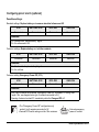
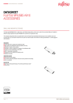
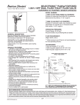
Paragon
Series
Status Information Card
Status Information Card
Installation
❑
❑
❑
❑
Switch off the Paragon UPS using the “on/off” button located on the front panel of the unit (see the
Paragon Series User Manual).
Disconnect from the power supply.
Unscrew the communication card cover at the rear of the unit.
The default pin settings can be modified (optional pinout configuration procedure):
- pin 2: used for the “replace battery” signal in the default configuration, but can be reconfigured for the
“emergency off” command.
- pin 5: provides a common electrical reference for all signals. Connected to 0-volts in the default
configuration but can be reconfigured for volt-free contacts.
(See “configuring pins 2 and 3” below for further information on modifying the default configuration.)
- Insert the status information card.
- Secure the card with the screws.
Functions
This relay card provides you with a simple means of transmitting data to a management system, a PLC, or a
computer system, using a 9-pin connector with the following pinout:
❑
❑
Pin 1: chassis ground.
Pin 2: contact closed when the battery must be
replaced.
A battery test is performed when the UPS is first powered on,
then again weekly (adjustable with UPS Driver). If a battery fault
is detected, the contact closes.
❑
❑
❑
❑
❑
❑
OV
5 4 3 2 1
9 8 7 6
Imax = 1A
no nc no no no no
Pin 4: contact open when operating on battery supply.
Pin 5: common electrical reference for all signals (0V).
Pin 6: contact closed when operating on automatic bypass.
Pin 7: contact closed when a “low battery” warning is received.
Pin 8: contact closed when your application is powered via a UPS.
Pin 9: contact closed when operating on battery supply.
2 Status Information Card
Relay breaking capacity:
Vmax = 25V DC
no = normally open
nc = normally closed
Configuring pins 2 and 5 (optional)
Possible settings:
Standard settings: Replace battery and common electrical reference at 0V.
JP01
BATT.FAIL JP02
EPO JP03
GND JP04
Connected
Connected
Removed
Connected
Comments
• Pin 2 delivers the “replace battery” signal.
• Pin 5 is referenced to 0V.
Customer settings: Replace battery and volt-free contacts.
JP01
BATT.FAIL JP02
EPO JP03
GND JP04
Connected
Connected
Removed
Removed
Comments
• Pin 2 delivers the “replace battery” signal.
• Pin 5 is volt-free.
Customer setting: Emergency Power Off (EPO).
JP01
BATT.FAIL JP02
EPO JP03
GND JP04
Removed
Removed
Connected
Connected
Comments
• Pins 2 and 5 receive the customer “Emergency Power Off” command: S1 wiring, max.
length 10m, see diagram below (pin 5 remains connected to 0V).
• Opening of external contact S1 immediately shuts the Paragon UPS off.
• The “Emergency Power Off” configuration only
works if pin 5 remains connected to 0V.
• Remote EPO switch wiring must be 10m maximum.
S1
5 4 3 2 1
9 8 7 6
External emergency
power off contact.
Status Information Card 3
Paragon Series
Status Information Card