1
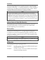
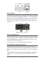
IE-MiniFiberLinX-II
Operation Manual
FCC Radio Frequency Interference Statement
This equipment has been tested and found to comply with the limits for a Class A computing device, pursuant to Part 15 of the FCC Rules.
These limits are designed to provide reasonable protection against harmful interference when the equipment is operated in a commercial
environment. This equipment generates, uses and can radiate radio frequency energy and, if not installed and used in accordance with the
instruction manual, may cause harmful interference to radio communications. Operation of this equipment in a residential area is likely to
cause harmful interference in which the user will be required to correct the interference at his own expense.
Any changes or modifications not expressly approved by the manufacturer could void the user’s authority to operate the equipment.
The use of non-shielded I/O cables may not guarantee compliance with FCC RFI limits. This digital apparatus does not exceed the Class A
limits for radio noise emission from digital apparatus set out in the Radio Interference Regulation of the Canadian Department of
Communications.
Le présent appareil numérique n’émet pas de bruits radioélectriques dépassant les limites applicables aux appareils numériques de classe A
prescrites dans le Règlement sur le brouillage radioélectrique publié par le ministère des Communications du Canada.
Warranty
IMC Networks warrants to the original end-user purchaser that this product, EXCLUSIVE OF SOFTWARE, shall be free
from defects in materials and workmanship under normal and proper use in accordance with IMC Networks' instructions
and directions for a period of six (6) years after the original date of purchase. This warranty is subject to the limitations set
forth below.
At its option, IMC Networks will repair or replace at no charge the product which proves to be defective within such
warranty period. This limited warranty shall not apply if the IMC Networks product has been damaged by unreasonable
use, accident, negligence, service or modification by anyone other than an authorized IMC Networks Service Technician
or by any other causes unrelated to defective materials or workmanship. Any replaced or repaired products or parts carry
a ninety (90) day warranty or the remainder of the initial warranty period, whichever is longer.
To receive in-warranty service, the defective product must be received at IMC Networks no later than the end of the
warranty period. The product must be accompanied by proof of purchase, satisfactory to IMC Networks, denoting
product serial number and purchase date, a written description of the defect and a Return Merchandise Authorization
(RMA) number issued by IMC Networks. No products will be accepted by IMC Networks which do not have an RMA
number. For an RMA number, contact IMC Networks at PHONE: (800) 624-1070 (in the U.S and Canada) or (949) 4653000 or FAX: (949) 465-3020. The end-user shall return the defective product to IMC Networks, freight, customs and
handling charges prepaid. End-user agrees to accept all liability for loss of or damages to the returned product during
shipment. IMC Networks shall repair or replace the returned product, at its option, and return the repaired or new
product to the end-user, freight prepaid, via method to be determined by IMC Networks. IMC Networks shall not be
liable for any costs of procurement of substitute goods, loss of profits, or any incidental, consequential, and/or special
damages of any kind resulting from a breach of any applicable express or implied warranty, breach of any obligation
arising from breach of warranty, or otherwise with respect to the manufacture and sale of any IMC Networks product,
whether or not IMC Networks has been advised of the possibility of such loss or damage.
EXCEPT FOR THE EXPRESS WARRANTY SET FORTH ABOVE, IMC NETWORKS MAKES NO OTHER WARRANTIES,
WHETHER EXPRESS OR IMPLIED, WITH RESPECT TO THIS IMC NETWORKS PRODUCT, INCLUDING WITHOUT
LIMITATION ANY SOFTWARE ASSOCIATED OR INCLUDED. IMC NETWORKS SHALL DISREGARD AND NOT BE
BOUND BY ANY REPRESENTATIONS OR WARRANTIES MADE BY ANY OTHER PERSON, INCLUDING EMPLOYEES,
DISTRIBUTORS, RESELLERS OR DEALERS OF IMC NETWORKS, WHICH ARE
INCONSISTENT WITH THE WARRANTY SET FORTH ABOVE. ALL IMPLIED WARRANTIES INCLUDING THOSE OF
MERCHANTABILITY AND FITNESS FOR A PARTICULAR PURPOSE ARE HEREBY LIMITED TO THE DURATION OF THE
EXPRESS WARRANTY STATED ABOVE.
Every reasonable effort has been made to ensure that IMC Networks product manuals and promotional materials
accurately describe IMC Networks product specifications and capabilities at the time of publication. However, because of
ongoing improvements and updating of IMC Networks products, IMC Networks cannot guarantee the accuracy of printed
materials after the date of publication and disclaims liability for changes, errors or omissions.
i
Table of Contents
FCC Radio Frequency Interference Statement .....................................................i
Warranty.............................................................................................................i
About the IE-MiniFiberLinX-II.............................................................................1
iView² Management Software ............................................................................1
Installation .........................................................................................................3
Mini-Serial Port ..................................................................................................3
LED Operation...................................................................................................3
Powering Options ..............................................................................................4
Features and Configuration ................................................................................4
Auto Negotiation, Duplex Mode and Speed.......................................................4
Assigning IP Information .....................................................................................8
Configuration .....................................................................................................9
Software Configuration.......................................................................................9
Main Configuration Screen...............................................................................10
Removing Trap Destinations.............................................................................12
Using iView2 ....................................................................................................27
Configuration File Save/Restore Function..........................................................29
Product Applications ........................................................................................36
Modes of Operation.........................................................................................37
Troubleshooting ...............................................................................................40
IE-MiniFiberLinX-II Modes of Operations..........................................................41
Specifications ...................................................................................................42
Fiber Optic Cleaning Guidelines.......................................................................43
Electrostatic Discharge Precautions...................................................................43
Safety Certifications..........................................................................................44
ii
About the IE-MiniFiberLinX-II
The IE-MiniFiberLinX-II is an optical demarcation network interface device, allowing
fiber network operators to connect to and manage remote network segments.
Advanced networking capabilities allow operators to easily observe both end points
and the fiber link between them as a single management entity, rather than as
separate networks. No host management traffic is visible to the remote or customer
network nor is access to the customer network required, guaranteeing end-to-end
data integrity. The IE-MiniFiberLinX-II offers 802.3ah OAM (passive), with firmware
version B5 or higher. Management is also available via the copper port. See Mode
One for configuration instructions.
The IE-MiniFiberLinX-II includes one 100 Mbps fiber port (OPTICS), one 10/100
twisted pair data port (DATA), and one auxiliary Craft port for serial configuration
(with the included adapter). The twisted pair port can Auto Negotiate or be set
manually for 10 or 100 Mbps, and half or full-duplex. The optics port operates at
100 Mbps, full duplex mode only. Powering options include AC and DC power as
well as Power over Ethernet, functioning as a Powered Device (PD) compliant with
802.3af.
The IE-MiniFiberLinX-II is 802.1Q VLAN compatible, supporting a full-range of VLAN
IDs, and offering Q-in-Q tagging and a 2-tier queue for differential prioritization
(802.1p). The IE-MiniFiberLinX-II also includes the LinkLoss and FiberAlert as well as
LinkFault Pass Through (LFPT) features for troubleshooting, loopback testing
functionality, bi-directional bandwidth control, and optional protection against
Broadcast storms. IMC Networks offers a Graphical User Interface (GUI) based
element management system called iView², which runs on SNMP.
Single-strand fiber versions of the IE-MiniFiberLinX-II allow two wavelengths to share
one fiber strand — Full-Duplex data travels on different wavelengths for example,
1310 nm and 1550 nm — doubling the capacity of fiber.
Management
The IE-MiniFiberLinX-II is capable of accepting IP-based management traffic from its
Data and/or Fiber ports. Management can be configured on either port via the iView2
software, and requires firmware version B5 or higher. When connected to an iMcVFiberLinX-II, Host-to- Remote management is IP-less.
iView² Management Software
iView² is a network management application for IMC Networks’ intelligent
networking devices. It features a GUI, which provides network managers the ability
to monitor and control IMC Networks’ products. The application is available in
several versions and can also function as a snap-in module for HP OpenView
1
Network Node Manager. Refer to the iView² help files for information regarding
configuring and managing the IE-MiniFiberLinX-II.
iView² supports the following platforms:
•
•
•
Windows NT
Windows 2000
Windows XP
iConfig Utility
iConfig is an in-band utility created by IMC Networks, used for SNMP configuration
for IMC Networks’ SNMP-manageable devices.
The iConfig feature allows the following to be performed:
•
•
Set an IP address, subnet mask and default gateway
Define community strings and SNMP traps
iConfig also includes an authorized IP address system and restricted access to MIB
groups which are supported by IMC Networks’ manageable devices. These extra
layers of security do not affect SNMP compatibility. iConfig can upload new versions
of the system software and new MIB information. It also includes diagnostic
capabilities for faster resolution of technical support issues.
Default Username/Password
The default user ID and password for both iConfig and Telnet are the following:
User: admin / Password:admin
2
Installation
To install the IE-MiniFiberLinX-II into a network environment, connect the proper
twisted-pair and fiber cables. In a standalone configuration, or if direct management
is desired, assign an IP Address to the IE-MiniFiberLinX-II after installation. Refer to
Assigning IP Information for information on assigning an IP Address.
NOTE
Since single-strand fiber products use optics that transmit and receive on two different
wavelengths, single-strand fiber products must be deployed in pairs or connected with two
compatible IMC Networks single-strand fiber products. For example, connect IE-MiniFiberLinXII, TX/SSFX-SM1310-SC (which has 1310 xmt and 1550 rcv) to a product which has 1550 xmt
and 1310 rcv, e.g. iMcV-FiberLinX-II, TX/SSFX-SM1550-SC. The two connected products must
also have the same speed and distance capabilities (i.e. both are single-mode [20 km] or both
are single/PLUS [40 km]).
Autocross Feature for Twisted Pair Connection
All twisted pair ports on the IE-MiniFiberLinX-II include AutoCross, feature that
automatically selects between a crossover workstation and a straight-through
connection depending on the connected device.
Mini-Serial Port
Included with the IE-MiniFiberLinX-II is a serial port adapter for configuration.
A standard AC mini-jack on the IE-MiniFiberLinX-II provides a local RS-232, Craft
interface for management. A special mini-jack to DF-9F cable is provided for direct
connection to a PC serial port.
NOTE
To log on through the serial port, set the computer/terminal for VT-100 emulation, with; 38.4K
baud, 8 data bits, 1 stop bit, no parity, no FlowControl.
LED Operation
The IE-MiniFiberLinX-II features two diagnostic LEDs:
FX LNK/ACT
This LED is on when a FX Link exists and blinks when data passes
through the fiber connection.
TX LNK/ACT
This LED is on when a TX Link exists and blinks when data passes
through the twisted-pair connection.
3
Powering Options
The IE-MiniFiberLinX-II powering options include AC and DC power as well as Power
over Ethernet, functioning as a PD compliant with 802.3af. The DC Terminal block
allows you to daisy-chain one IE-MiniFiberLinX-II to another. To use the DC terminal
block, connect to any one positive and any one negative terminal from a power
source. The illustration shows the wiring configurations for the DC terminal block (7
to 50 VDC).
Features and Configuration
The IE-MiniFiberLinX-II offers a full feature set including Auto Negotiation, Selective
Advertising, FiberAlert, AutoCross, read/write VLANs, SNMP management, bandwidth
control, and loopback testing. Features can be configured through software or via a
serial port, Telnet session, iConfig or SNMP.
Unit software updates can be downloaded through TFTP and iConfig.
Auto Negotiation, Duplex Mode and Speed
The twisted pair port on the IE-MiniFiberLinX-II Auto Negotiates for speed and
duplex mode. The optics port does not Auto Negotiate; it operates at 100 Mbps FullDuplex. Use the management software to configure the features on the twisted pair
ports.
The IE-MiniFiberLinX-II ships from the factory with Auto Negotiation enabled on the
twisted pair port. In this mode, the port automatically negotiates for speed and
duplex.
4
The twisted pair port on the IE-MiniFiberLinX-II can also be manually set for 10 Mbps
or 100 Mbps operation and for Half- or Full-Duplex (i.e. 10 Mbps Full-Duplex, 10
Mbps Half-Duplex, 100 Mbps Full-Duplex or 100 Mbps Half-Duplex).
Selective Advertising, when used in combination with Auto Negotiation, advertises
only the configured speed and duplex mode for the twisted pair port. If a specific
speed and/or duplex mode is desired, Selective Advertising should be used rather
than Force Mode, when connecting to devices that ONLY Auto Negotiate.
Bandwidth Control
The IE-MiniFiberLinX-II includes bi-directional bandwidth control, which can be
independently set in 32 Kbps increments up to 100 Mbps. Bandwidth control can be
configured through iView² or a console session. The device features an integrating
algorithm with a 64 Kb buffer, allows traffic bursts, to prevent lost data. This allows
operators to offer tiered services. See the iView² for configuration information.
FX LinkLoss, TX LinkLoss and FiberAlert
During normal operation, link integrity pulses are transmitted by all point-to-point
Ethernet devices. When an IE-MiniFiberLinX-II receives valid link pulses, it knows the
device to which it is connected is up, and the copper or fiber cable coming from that
device is intact. The appropriate link LED is lit to indicate this. For troubleshooting
information using the LinkLoss and FiberAlert features of the IE-MiniFiberLinX-II
modules, refer to the Troubleshooting section of this manual.
WARNING
The FiberAlert and LinkLoss features cause data interruptions designed to alert remote sites of
line failures. These data interruptions can be misinterpreted as module failures when these
features are enabled. Enable these features only when the resulting data interruptions and
causes are well understood.
FX LinkLoss
FX LinkLoss is link integrity monitoring feature that forwards fiber link faults to the RJ45 DATA port to indicate that a fiber link fault has occurred.
TX LinkLoss
TX LinkLoss is a link integrity monitoring feature that forwards an RJ-45 link fault to
the fiber connected device to indicate that a link fault has occurred.
FiberAlert
FiberAlert minimizes the problems associated with the loss of one strand of fiber.
Normally when a single strand of fiber is lost, the transmitting side of the connection
is unaware that there is a fault. FiberAlert returns faults back on the fiber they came
in on.
5
Using LinkLoss and FiberAlert
In a typical central site to remote site media conversion, it is recommended the
LinkLoss and FiberAlert features are enabled as indicated in the following:
Feature
FiberAlert
TX LinkLoss
FX LinkLoss
FiberAlert and LinkLoss
Enabled
Fault Location
Remote Side Only
Remote Side (or both)
Host Side (or both)
Fiber
Twisted Pair
Fiber
Port Affected
Fiber
Fiber
Twisted Pair
WARNING
Do not enable FiberAlert on both modules when using them in pairs. This will cause them to
lock up when a fault occurs on the fiber. Only enable FiberAlert on the remote module.
Link Fault Pass Through (LFPT)
Link Fault Pass Through is a troubleshooting feature that combines TX and FX
LinkLoss from both the local and remote modules. LFPT is enabled by turning on
both FX and TX LinkLoss on both modules. This feature allows either end of the
conversion to detect a link fault occurring at the other end of the media conversion
chain.
Regardless whether a break occurs on a copper or fiber segment between the End
device and the media converter, or between the two media converters, End devices
at both ends.
6
Regardless if there is a break in segment 1, 2 or 3, the link will drop on the switches
at both ends.
The link fault is passed through the media conversion and is observed at each end. It
acts just like it would if the devices were directly connected.
Loopback Testing
The IE-MiniFiberLinX-II includes Loopback testing functionality. During loopback
testing, management traffic entering the uplink port is still capable of managing the
device. This is selectable form the UNIT screen in a serial/Telnet session or through
iView².
The menu of choices in the CLI includes:
• No loopback, normal traffic mode
• Loopback Enabled
• Loopback, Source/Destination address swap
• Loopback, address swap and clear Multicast bit
• No learning on fiber or Data ports
The menu of choices in iView².includes:
• Off
• ON
• On- Address Swap
• On-Address swap + Clear MC
Loopback Testing on Remote or Standalone
No loopback, normal traffic mode
The standard mode in which the units function, either as stand-alone or
Host/Remote.
Loopback Enabled
Loopback mode without address swap
Loopback, Source/Destination Address Swap
A Layer 2 Ethernet switch will discard all received packets with the same MAC
address as sent packets. To avoid this issue the Loopback feature can swap the
source and destination MAC addresses on the looped data. (This selection can cause
a frame with a multicast source address to be created, which violates the IEEE
standard.)
Loopback, Address Swap and Clear Multicast Bit
In addition to swapping the source and destination MAC addresses on the looped
7
data, the Loopback feature can also be set to clear the multicast bit. This allows the
looped data to avoid being blocked by any multicast settings.
Loopback Testing in a Host/Remote configuration
The IE-MiniFiberLinX-II is strictly a CPE device; configuration on a Host would require
an iMcV-FiberLinX-II; select No Learning on OPTICS and DATA Ports on the Host; on
the Remote, choose SRC/DST Address Swap or Address Swap and Clear Multicast Bit.
Host: No Learning on OPTICS and DATA Ports
The Loopback feature can be set to disable address learning on the OPTICS (or
UPLINK) and DATA ports, allowing the loopback to be performed without
interference from MAC address filtering functions. This is a function on the HOST
unit. Set the REMOTE unit for Loopback then set the HOST to disable learning so
Loopback frames pass from the OPTICS port to the DATA port.
Remote: Source/Destination Address Swap
A Layer 2 Ethernet switch will discard all received packets with the same MAC
address as sent packets. To avoid this issue the Loopback feature can swap the
source and destination MAC addresses on the looped data.
OR
Address Swap and Clear Multicast Bit
In addition to swapping the source and destination MAC addresses on the looped
data, the Loopback feature can also be set to clear the multicast bit. This allows the
looped data to avoid being blocked by any multicast settings.
NOTE
Units should not be in the Default Mode when performing LoopBack tests.
Assigning IP Information
To utilize SNMP-management in a standalone environment, the IE-MiniFiberLinX-II
IP configuration information (e.g., IP address, subnet mask, etc.) must be assigned by
using iConfig (from iView²), by using the unit’s serial port or by using DHCP.
These methods will also allow you to create community strings, assign access rights,
configure traps and more. iConfig offers more options than serial port configuration.
After assigning the IE-MiniFiberLinX-II an IP address, use iView² or another SNMPcompatible Network Management System (NMS) for remote configuration,
monitoring and management.
8
Configuration
The IE-MiniFiberLinX-II includes many features that function automatically or are
configurable via iView², iConfig, or a serial/Telnet session.
Software Configuration
The following table presents port options configurable from iView² or from a
serial/Telnet session. Refer to the iView² section later in this chapter or the iView²
Help file for more information. For information on configuring VLANs, refer to the
Serial Configuration/Telnet Session section in this chapter.
Feature
iView²
9
9
9
9
9
9
9
9
FX/TX LinkLoss
FiberAlert
Loopback
Auto Negotiation
Selective Advertising
Force Mode
FlowControl
Bandwidth Control
VLANs
Serial/Telnet
9
9
9
9
9
9
9
9
9
The following table presents management options configurable via iConfig or a
serial/Telnet session.
Feature
PROM Software Download/Upload
Telnet Session
TFTP Trigger
Software Download Setup (TFTP)
DHCP
Configuration File/Save Restore
iView²
9
9
Serial/Telnet
9
9
9
9
The following options are configurable through both iConfig and Serial:
•
•
•
•
•
•
•
•
•
IP Address
Subnet Mask
Default Gateway
MIB Community
Traps Assignment
Users
Passwords
Access Level
Reboot
9
Main Configuration Screen
Press Enter, at the prompt, to display the main configuration screen.
The following displays are available:
Saved Values (displays changes made during current session)
• IP Address (must be assigned during initial configuration)
• Subnet Mask (must be assigned during initial configuration)
• Default Gateway (default router for IP traffic outside subnet)
• Server IP Addr (for the TFTP server)
• New Prom File (firmware file name)
Current Values (displays values currently in use)
• IP Address (IP address of SNMP agent)
• Subnet Mask (mask to define IP subnet)
• Default Gateway (default router for IP traffic outside subnet)
• Server IP Addr (for the TFTP server)
• New Prom File (firmware file name)
NOTE
Reboot the IE-MiniFiberLinX-II for changes to take effect. To reboot, type reboot at the prompt
on the main configuration screen, or power cycle the chassis. If a Delete key is not available,
use the F2 key. Any changes to the configuration may result in a momentary loss of connection.
10
Command List
I
P
T
K
C
U
E
Reboot
D
Space Bar
=
=
=
=
=
=
=
=
=
=
Enter New Saved Parameter Values
Change Password
New Trap Destination
Remove ALL Trap Destinations
New Community String
Delete ALL Community Strings
End Session
Reboots the IE-MiniFiberLinX-II
Enable/disable DHCP
Opens the Device Specific Configuration Options
Assigning TCP/IP Information
To modify the Saved Parameter Values (i.e., assign IP address and subnet mask), press
I. Then, enter the IP address and subnet mask for the connected device, pressing
Enter after each. A default gateway can also be assigned, or press Enter to skip.
When finished, press Enter, then type reboot for changes to take effect. The Current
Values can only be saved and acted on after the IE-MiniFiberLinX-II has been
successfully rebooted.
Password Protection for Serial Port Connections
Password protection is provided for the serial configuration process by pressing P on
the main configuration screen. Enter a password, keeping in mind that passwords are
case-sensitive and must not exceed eight characters or include spaces, and press
Enter. This password will be requested whenever logging on. To remove password
protection, select P and, instead of entering a password, press Enter. If a password
becomes lost, contact IMC Networks Technical Support at (949) 465-3000 or (800)
624-1070.
Assigning Trap Destinations
Traps are sent by the manageable device to a management PC when a certain event
takes place. To enter a trap destination, press T. At the “Enter a New IP Address.”
prompt, enter the appropriate IP address and press Enter. Then, type the name of
the community string (that the destination device has been configured to accept) and
press Enter. This function enables ALL of the device traps. To individually activate
and deactivate traps, use iConfig for configuration. Supported traps include: Link
Down, Link Up, Cold Start, Warm Start and Authentication Failure.
11
Removing Trap Destinations
To remove all trap destinations, press K. Press Y to continue to confirm or N to abort
and then, press Enter. To selectively remove community strings, use iConfig to
configure the device.
Creating Community Strings
Community strings add a level of security to a network. The default community string
is named “public” and has read/write access. “Public” should be replaced with
custom community strings such as one with read-only access (for general use), the
other with read/write access (for the administrator).
Steps:
1.
Type C on the main configuration screen.
2.
Enter the name of the new community (up to 16 characters, no spaces) and
press Enter.
3.
Type one of the following to assign the community string’s access rights:
R
W
Enter
=
=
=
read-only access
read/write access
abort
4.
After entering R or W, press Enter.
5.
To finish, press Enter, and reboot.
Deleting Community Strings
To delete all community strings, perform the following:
1.
Press U. The “Are you sure you want to delete all future strings?” prompt
displays.
2.
Press Y to proceed, N to abort.
3.
Press Enter.
This function will delete ALL community strings. To selectively delete community
strings, use iConfig to configure the device.
Ending the Session
Be sure to press E to end a serial port or Telnet/HyperTerminal session, before
disconnecting the cable. This will stop the continuous stream of data to the serial
port.
12
Rebooting the Unit
To reboot the IE-MiniFiberLinX-II, type reboot.
Enabling/Disabling DHCP
To toggle DHCP on the IE-MiniFiberLinX-II between enable and disable, press D.
Additional Device-Specific Commands
The IE-MiniFiberLinX-II also includes the following device-specific options.
To access these options, perform the following:
1.
Press the Space Bar when in the Command List section of the Main
Configuration screen (serial configuration/Telnet session).
2.
Type the name of the action (shown below) and press Enter.
cleandb
download
ifStats
rmStats
version
reboot
security
port
Reboots the unit with a clean database. This removes all information from
the database and sets the unit to factory defaults.
Downloads firmware via the TFTP protocol
Displays Ethernet statistics
Displays RMON statistics
Displays the unit’s serial number and build date
Reboots the unit and clears all internal counters.
Allows ARP request configuration. This setting is only for very unique
configurations and should not be adjusted.
Displays and changes port settings, such as duplex status and speed.
13
config
accounts
sysdescr
unit
bw
sfpstats
Allows VLAN and transparency mode configurations.
Allows the addition of new users.
Allows the editing of sysName, sysDescr, and Port information
text.
Unit Global Setting
Bandwidth Limiting Controls
Provides information about the wavelength, serial number, output power,
BER, and other useful information.
Cleandb
Entering cleandb reboots the unit with its database cleaned depending on the option
selected. Users are presented with two, sequential options, first to reset all SNMP
settings and, second, to reset all of the unit’s configuration to default. Enabling the
first option presents the second. Resetting the unit to factory default values (option
two) will delete all custom IP and VLAN settings.
Downloading Files
Firmware for the IE-MiniFiberLinX-II can be downloaded from a central server via
TFTP protocol. Initiate this download via serial configuration or Telnet session. To
download a file, type download and press Enter to be taken to the Download a file
screen. This screen displays the IP Address of the TFTP server and the name of the
file to be downloaded. The TFTP server should be open. Make sure the IP Address
and the name of the file are correct in the Current Values section of the Main
Configuration screen. These are changed by entering I from the Main Configuration
screen. Press Enter to start downloading the file.
Viewing Port Statistics
To view port statistics on the IE-MiniFiberLinX-II, enter ifstats. This will open a screen
displaying information on packets received and transmitted as defined by MIB-II
standard RFC 1213.
Pressing the Space Bar will refresh the data on the screen.
14
Viewing Port RMON Statistics
To view port RMON (Remote MONitoring) statistics on the IE-MiniFiberLinX-II, enter
rmstats. This will display RMON information on packets received as defined in RFC
2819 for RMON.
Pressing the Space Bar will refresh the data on the screen.
Version
Entering version will display the version of the firmware operating the IEMiniFiberLinX-II.
15
NOTE
In the examples shown, ports are referred to as how they appear on the unit itself. Some
screens may show TX and FX for the port titles. In this case, TX = DATA port and FX = OPTICS
port.
Reboot
Entering reboot will save settings and reboot the IE-MiniFiberLinX-II.
Setting Security
Security settings on the IE-MiniFiberLinX-II are reserved for non-standard
configurations. Most users won’t utilize this screen. Security configuration should
only be utilized when non-standard networking equipment is being employed. Enter
Y to set new security settings or any other key to abort.
The next screen that appears will configure ARP settings, such as the destination
address of ARP messages along with Ethernet Types. Enter the new data, then press S
to save the settings or Q to quit.
Port Configuration
Serial/Telnet sessions display port status as well as allowing configuration of some port
features. Type port and press Enter to be taken to the Port screen. From this screen,
view the port speed, duplex and link status.
The Port screen contains the following commands:
Port Enable
Admin Status
Port Speed
Ctrl
Advertise Ctrl
Enable/Disable the port. (Select Enable to enable the port.)
Set Administration level. (Select UP to enable the port.)
Both settings must be enabled to enable the port.
Set the port manually or for Auto Negotiation.
This is the Selective Advertising feature. Selective Advertising,
when used in combination with Auto Negotiation, advertises the
configured speed and duplex mode for the twisted pair ports.
Auto Negotiation must be enabled for Selective Advertising.
NOTE
Selective Advertising must be used when connecting to a device that Auto Negotiates and a
specific speed and duplex mode is desired.
16
Advertise FlowC and Force FlowCtrl - This is the FlowControl feature.
•
•
•
•
When using FlowControl functionality on any port, enable Global FlowControl.
Then, configure each port individually.
When using Auto Negotiation and FlowControl, set Advertise FlowC to Advertise
Flow and set Force FlowCtrl to Flow Auto.
Set Advertise FlowC to No Flow to disable FlowControl on a given port.
When using FlowControl and Force Mode on a given port, set Advertise FlowC
to Advertise Flow and set Force FlowCtrl to Frc FlowCt.
Unit FlowControl
This enables/disables FlowControl functionality on the unit and
must be enabled for FlowControl to function on any port.
Operational Mode Configuration
As referenced in Product Applications, there are six modes of operation that can be
configured through the Serial/Telnet session. All of the modes of operation will block
management traffic on the Data port.
The configuration screen is accessed by typing config and pressing Enter from the
Additional Commands screen.
Mode One – Default and Default Plus
The default mode is designed to pass untagged traffic only. Press F4 to return to the
Additional Device-Specific Commands screen. In Default Mode Plus, all tagged and
untagged traffic passes between the data and optics ports. Management to the device
must be untagged.
17
How to configure the IE-MiniFiberLinX-II for management on the
copper port
1.
Configure the device to be set in the default mode. If unsure of the device's
configuration, perform a cleandb which will set the device to the default setting.
This resets the IP address (see page 14 for information on the cleandb function).
2.
Make sure that the version of firmware is 722-10b5 or higher.
3.
Telnet into the device.
Press Enter for device configuration mode.
18
Press the Space Bar once for access to additional commands.
Type config then press Enter to set the operation mode.
19
Press Enter for other options.
Press 2 to change to Default Plus Mode, then press Enter.
Press Y to allow TX management, then press Enter.
20
Press S to save the configuration.
Reboot the device and use the SNMP software to manage the device over the copper
port.
Mode Two - Transparency with Untagged Management
This mode is designed to pass all tagged and extra-tagged customer traffic unchanged
and must be managed using untagged traffic only. It does not add or remove tags.
Select Y on the initial config screen and from the Transparent Mode Setup screen,
select N in the fields.
21
Mode Three - Transparency with Tagged Management
This mode will pass all tagged and untagged customer traffic. Management traffic
must be tagged. It does not add or remove tags.
Select Y on the initial config screen. From the Transparent Mode Setup screen, select
Y and enter the Management Tag.
22
Mode Four - Transparency with Extra Tagging (or Q-in-Q)
This mode is designed to either pass all customer traffic with the defined extra tag (Qin-Q) or add and remove the defined extra tag (Q-in-Q) on all customer traffic.
Management traffic can be tagged or untagged.
Select Y on the initial config screen and then, select Y when asked to select Extra
Tags. When setting this operation mode, the question “Are Extra Tags left on the
Data Port” should be answered NO for the remote IE-MiniFiberLinX-II and YES for
the host connection.
Mode Five - VLAN Filter
This mode is designed to only pass traffic with any of the 32 tags that have been
identified in the user-defined table. No untagged traffic can pass and management
traffic must be tagged. No tags are added or removed from the traffic. Select N on
the initial config screen and then setup the VLAN screen.
VLAN IDs can be any number between 1 and 4,094.
23
Mode Six - Port VLAN
This mode tags all customer traffic received by the copper port going to the fiber port,
untagging traffic conversely. This tag is entered as the Data VLAN tag with the optical
Tags selected as YES to indicate it is added at the egress of the optical port.
Select N on the initial config screen and then setup the VLAN screen.
The table below displays how the settings are entered.
VLAN
Optical
Data
Mgmt (SNMP)
Priority
Tag2
Tag1
4
1
System Description
24
Tags
Yes
No
Yes
Sysdescr offers the options of assigning a system name, System Contact System
Location, Unit Description and individual Port names. Enter a description or name,
up to 32 characters per line. Press the Enter key to complete the editing task.
To change the MIB name of the IE-MiniFiberLinX-II as it appears on the network,
type sysname and press Enter. Enter a new name, not exceeding 16 characters in
length.
Unit Control Settings
Serial/Telnet sessions display unit status as well as allowing configuration of some of
the IE-MiniFiberLinX-II features. Type unit and press Enter to be taken to the Unit
screen. From this screen, view the settings for FlowControl, FiberAlert, LoopBack,
Maximum Frame Size, and 802.1p Base Priority.
NOTE
Requires firmware version B2 or higher.
Use the arrow keys to navigate and the Space Bar to change the values on this screen.
These settings include:
Unit FlowControl
Unit FiberAlert
Unit LoopBack
Unit Max FrameSz
Enable/Disable FlowControl
Enable/Disable FiberAlert
Enable/Disable the various LoopBack testing modes
Set the maximum Frame Size to pass through the ports:
1518, 1522, 1536, or 1916.
25
802.1p Base Pri
Set the level of 802.1p base priority (3 or 4).
The IE-MiniFiberLinX-II has two outgoing queues; one for
high priority traffic and one for low priority traffic. If the Base
VLAN Priority is 4 for example, 0-3 are low priority and 4-7
are high priority. If the Base VLAN Priority is changed to 3,
0-2 are low priority and 3-7 are high priority.
Serial Configuration/Telnet Session
Access to the IE-MiniFiberLinX-II can be managed by typing accounts and pressing
Enter from the command screen.
On the screen that appears, press A to add a user, entering the user’s information in
the appropriate fields. To delete a user, press D for the user selected. Pressing any
other button will exit this screen.
NOTE
User rights only allow viewing of status/settings but not changing of settings.
To log onto the unit through the serial port, connect a PC to the IE-MiniFiberLinX-II
using the included adapter. Set the computer/terminal for VT-100 emulation, with
the following settings: 38.4K baud, 8 data bits, 1 stop bit, no parity, no FlowControl.
Enter the User Name and Password as admin (which is the default setting), when
connecting through Telnet/HyperTerminal. A new User Name and Password should
be set after signing on the first time.
Assign the IE-MiniFiberLinX-II an IP address before using a Telnet session (the default
IP address is 10.10.10.10). All configurations performed using the serial port can
also be performed using Telnet. Multiple accounts can be assigned with individual
names and passwords.
Each account can be assigned one of the following authority roles:
User
This role can only see status, change a password, and reboot.
Operator
This role can perform User role functions and change settings.
26
Administrator
This role can perform Operator role functions, add/delete accounts,
and use the cleandb command. Account access through the serial
port is at the Administrators level (default).
DHCP
DHCP Disable (Static IP Addressing)
DHCP is disabled in the default configuration. Initially, modules are assigned
a Static default IP Address of 10.10.10.10. Changes to the Static IP Address
can be added manually through iConfig, an RS-232 Serial session, or Telnet.
The changes will be initiated following reboot of the module.
DHCP Enable (Dynamic IP Addressing)
If a DHCP server is present on the network and DHCP is enabled, the DHCP client
will initiate a dialogue with the server during the boot up sequence. The server will
then issue an IP address to the management card. Once the new IP address is
received, the SNMP Management Module will reboot so that the new IP address will
take effect. Refer to About Serial Port Configuration for more information about
Enabling/Disabling DHCP. When there is no DHCP server on the network, use
iConfig or serial configuration to manually set the IP addresses.
When DHCP is enabled, the IP address (default 10.10.10.10 or user configured) is
saved. When DHCP is disabled, the saved IP address will be reinstated and the
device will reboot.
DHCP servers give out lease times: devices renew their leases based on the
administrator-specified time. If a device cannot renew its lease, and the lease
expires, the device will be given the IP address 10.10.10.10 and will reboot.
Using iView2
iView² is IMC Networks’ management software, providing network management in
an easy to use GUI. Once iView² is installed on a network management PC using a
Windows operating system, use the Start menu to access iView².
NOTE
Windows SNMP services must be installed to receive traps.
The left side of the iView² screen will display the IMC Networks products on the
network. Click the connection for the IE-MiniFiberLinX-II to open its iView² screen.
The example shows a connection to a FiberLinX but this could vary depending on the
connection. When configuring the IE-MiniFiberLinX-II as a standalone unit, only the
IE-MiniFiberLinX-II will appear.
27
A navigation bar on the top of the screen displays the options for configuring the IEMiniFiberLinX-II connection.
These options include the following:
Host
Displays the configuration screen for the Host connection.
Remote
Displays the configuration screen for the Remote connection.
This will show the IE-MiniFiberLinX-II configuration information.
Information on this screen is provided on the following page.
NOTE
The Host and Remote buttons will not appear when configuring the IE-MiniFiberLinX-II alone. In
this setup, a Configuration button will appear with the same settings.
Bandwidth
Port Desc
Tables
Advanced
Agent Info
Refresh
Displays the Bandwidth Limitation Settings.
Displays a screen for setting port descriptions. Each name should not
exceed 32 characters or include any spaces.
Displays a screen showing network performance statistics.
Displays the IE-MiniFiberLinX-II advanced settings.
Displays information about the SNMP Management software.
Reloads the content of a window with the most current data.
28
The Configuration/Remote Screen
Depending on whether the IE-MiniFiberLinX-II is being set up as a standalone or in a
Host/Remote connection, the Configuration or Remote buttons will show a screen for
configuring the IE-MiniFiberLinX-II settings.
In addition to allowing setting changes on the IE-MiniFiberLinX-II, settings on the
ports can also be changed from the Configuration/Remote screen.
For information or instructions on the use of UMA (Unified Management Agent), refer
to the SNMP Management module manual.
Configuration File Save/Restore Function
Requirements
FiberLinX-II family series:
Minimum firmware version required:
IE-MiniFiberLinX-II: B1 or higher,
Required iView² version: 1.8.4 or higher
The Configuration File Save/Restore Function allows a user the ability to backup all
the configuration settings of a unit. With this backup, a user can restore settings to a
unit if necessary or use this backup to apply the same settings to a different unit.
All configurable managed objects are saved in a configuration file that is stored in the
unit’s Large File Area. This includes all configurable settings such as VLAN
29
configurations, IP Address configuration and SNMP agent settings. The configuration
file can be transferred from the unit to a PC and saved to disk through the iConfig
protocol. The configuration file can be transferred from a PC to a unit of the same
type through iConfig or TFTP into the unit’s Large File Area. After the transfer is
complete, the unit copies the configuration to flash and reboots.
The configuration file’s contents is device-type specific and can be identified by
iConfig as a configuration file as well as to what type of device it is applicable to.
How to Save a Configuration File
To save a configuration file, use the iConfig tool. Log into the unit through iConfig,
navigate to the iConfig Administration tab, select the “Save Configuration” button,
wherein a prompt requires a file name, as well as any user notes. From this point the
file will be transferred to the PC’s disk through the iConfig network protocol.
Once the file is saved to disk it can be restored to the device or sent to another like
device through iConfig or TFTP.
For iConfig
For TFTP
The user will log into a unit, select the Administration tab, select the
Upload Configuration button, be prompted to locate a
configuration file on the PC’s disk. From this point the file transfer
will take place from the PC to the unit. After a successful transfer,
the user will be prompted to Reboot to make the new configuration
active.
The user will log into the unit either through a serial port session or
through Telnet. They will navigate to the download command page,
enter the TFTP server’s IP address and enter the configuration file
name, then press Enter to start the download process. Once the
download is successful, the user will be prompted to apply the
settings. The device must be rebooted after applying the settings to
make them active.
By default, the IP Address configuration currently on the device is kept intact and not
overwritten by the new configuration file.
30
Configuration File Basics
Saving a Configuration File to Disk:
From the Administration Tab in iConfig click the Save Configuration button:
The user is prompted for a filename:
31
The user is prompted to enter any notes to the header of the saved file for future
reference when uploading the file through iConfig:
After the file transfer from the device to disk, the user is notified of the status:
32
Uploading a Saved Configuration File through iConfig
From the Administration Tab in iConfig click the Upload Configuration button:
The user will be prompted to select a configuration file. Once selected, the user can
also view any notes that were added when the file was saved:
After selecting the configuration file, the file upload process begins; when completed,
the user is notified of the status and also notified that a reboot is necessary for the
new configuration to become active:
33
Uploading a Saved Configuration File through TFTP
From the commands list in the CLI (Serial or Telnet) run the download command by
typing in download:
In the download command screen type in the IP Address of the TFTP server and the
file name to retrieve.
The user will be prompted to continue that retrieval process by pressing the ENTER
key or cancel by typing “Q”.
34
After the transfer process is complete the user will be prompted to press the Enter key
again to load the configuration file:
Once loaded into the device’s SNMP memory area, the user will be prompted to
reboot the device to make the new configuration active:
35
Product Applications
The IE-MiniFiberLinX-II comes with a variety of features for different network
environments. When used with different types of IMC Products, some features can
be enabled, such as extra tagging or “Q-in-Q”, and different network setups come
with different requirements. The network setup example below shows one
deployment scenario with a full range of management options.
The IE-MiniFiberLinX-II can be setup two ways:
•
•
One IE-MiniFiberLinX-II and an IMC Networks iMcV-FiberLinX-II for a
Host/Remote application (one at each end)
One IE-MiniFiberLinX-II for a standalone application
36
Modes of Operation
The following are application examples of Operation Modes for the IE-MiniFiberLinXII. There are six modes of operation that can be configured through the Serial/Telnet
session. All modes of operation block management traffic from the user network on
the Data port.
Mode One - Default
The default mode is provided to pass only untagged traffic.
Default Plus
The Default Mode Plus allows tagged and untagged traffic to pass between the data
and optics ports.
Mode Two - Transparency with Untagged Management
This mode is designed to pass all tagged and extra-tagged customer traffic unchanged
and must be managed using untagged traffic only. It does not add or remove tags.
37
Mode Three - Transparency with Tagged Management
This mode will pass all tagged and untagged customer traffic. Management traffic
must be tagged. It does not add or remove tags.
Mode Four - Transparency with Extra Tagging (or Q-in-Q)
This mode is designed to either pass all customer traffic with the defined extra tag (Qin-Q) or add and remove the defined extra tag (Q-in-Q) on all customer traffic.
Management traffic can be tagged or untagged.
38
Mode Five - VLAN Filter
This mode is designed to only pass traffic with any of the 32 tags that have been
identified in the user-defined table. No untagged traffic can pass and management
traffic must be tagged. No tags are added or removed from the traffic.
NOTE
VLAN IDs can be any number between 1 and 4,094.
Mode Six - Port VLAN
This mode tags all customer traffic received by the copper port going to the fiber port,
untagging traffic conversely. Management traffic must be tagged.
39
Troubleshooting
If a fiber connection cannot be established, perform the following to make sure that
the fiber transceivers on the IE-MiniFiberLinX-II are not over/under driving the fiber
receivers:
1.
Make sure the fiber wavelength on both connected devices match (i.e. both are
1310 nm single-mode fiber).
2.
Make sure that FiberAlert is enabled on only one unit when connecting an IEMiniFiberLinX-II to another IMC Networks media converter with the FiberAlert
feature.
3.
Make sure the twisted-pair port speed on the IE-MiniFiberLinX-II matches that of
the end devices connected to the IE-MiniFiberLinX-II. Configure the IEMiniFiberLinX-II and its link partner to Auto Negotiation or, if using Force mode,
be sure speed and duplex match.
4.
Management (VLAN tagged or Untagged) traffic will not be allowed to pass
through the DATA port and will only pass through the FIBER port.
5.
When using the IE-MiniFiberLinX-II as a PD device, establish power first, check
the LEDs to confirm this, and then connect the serial port in order to configure
the device via a console session. If performing the steps in the reverse order, the
unit will appear non functional. The same is true if connecting a DC terminal
block.
To restore the unit to factory default settings, use the cleandb function from the serial
port management feature.
40
IE-MiniFiberLinX-II Modes of Operations
For enlarged version go to IMC Networks website:
http://www.imcnetworks.com/Products/12_IE-MiniFiberLinX-II.html
41
The Agent Info Screen
Information about the SNMP Agent software managing the IE-MiniFiberLinX-II is
contained on this screen.
Specifications
Input Specifications
AC Wall Adapter
100 to 240 ±10% V AC input, 5V DC output
DC Input Voltage
1A @ 5V DC to 0.1A @ 50V DC
IEEE 802.3af Power over Ethernet
Humidity
5 to 95% (non-condensing)
Operating Temperature
-31° to 158° F (-35° to 70° C) DC configuration
32° to 122° F (0° to 50° C) with AC wall adapter
Storage Temperature
-49° to 185° F (-45° to +85° C)
Shipping Weight
0.30 lbs (0.11 kg)
Dimensions
0.83”H x 1.80”W x 3.35”D (2.11 x 4.57 x 8.51 cm)
42
Fiber Optic Cleaning Guidelines
Fiber Optic transmitters and receivers are extremely susceptible to contamination by
particles of dirt or dust, which can obstruct the optic path and cause performance
degradation. Good system performance requires clean optics and connector ferrules.
1.
Use fiber patch cords (or connectors, if you terminate your own fiber) only from
a reputable supplier; low-quality components can cause many hard-to-diagnose
problems in an installation.
2.
Dust caps are installed at IMC Networks to ensure factory-clean optical devices.
These protective caps should not be removed until the moment of connecting
the fiber cable to the device. Should it be necessary to disconnect the fiber
device, reinstall the protective dust caps.
3.
Store spare caps in a dust-free environment such as a sealed plastic bag or box
so that when reinstalled they do not introduce any contamination to the optics.
4.
If you suspect that the optics have been contaminated, alternate between
blasting with clean, dry, compressed air and flushing with methanol to remove
particles of dirt.
Electrostatic Discharge Precautions
Electrostatic discharge (ESD) can cause damage to any product, add-in modules or
stand alone units, containing electronic components. Always observe the following
precautions when installing or handling these kinds of products
1.
Do not remove unit from its protective packaging until ready to install.
2.
Wear an ESD wrist grounding strap before handling any module or component.
If the wrist strap is not available, maintain grounded contact with the system unit
throughout any procedure requiring ESD protection.
3.
Hold the units by the edges; do not touch the electronic components or gold
connectors.
4.
After removal, always place the boards on a grounded, static-free surface, ESD
pad or in a proper ESD bag. Do not slide the modules or stand alone units over
any surface.
WARNING! Integrated circuits and fiber optic components are
extremely susceptible to electrostatic discharge damage. Do not
handle these components directly unless you are a qualified service
technician and use tools and techniques that conform to accepted
industry practices.
43
Safety Certifications
UL/CUL: Listed to Safety of Information Technology Equipment, including
Electrical Business Equipment.
CE: The products described herein comply with the Council Directive on
Electromagnetic Compatibility (2004/108/EC) and the Council
Directive on Electrical Equipment Designed for use within Certain
Voltage Limits (2006/95/EC). Certified to Safety of Information
Technology Equipment, Including Electrical Business Equipment. For
further details, contact IMC Networks.
Class 1 Laser product, Luokan 1 Laserlaite,
Laser Klasse 1, Appareil A’Laser de Classe 1
European Directive 2002/96/EC (WEEE) requires that any equipment that bears this
symbol on product or packaging must not be disposed of with unsorted municipal
waste. This symbol indicates that the equipment should be disposed of separately
from regular household waste. It is the consumer’s responsibility to dispose of this
and all equipment so marked through designated collection facilities appointed by
government or local authorities. Following these steps through proper disposal and
recycling will help prevent potential negative consequences to the environment and
human health. For more detailed information about proper disposal, please contact
local authorities, waste disposal services, or the point of purchase for this equipment.
44
19772 Pauling • Foothill Ranch, CA 92610-2611 USA
TEL: (949) 465-3000 • FAX: (949) 465-3020
www.imcnetworks.com
© 2009 IMC Networks. All rights reserved.
The information in this document is subject to change without notice. IMC Networks assumes no responsibility for any
errors that may appear in this document. IE-MiniFiberLinX-II is a trademark of IMC Networks. Other brands or product
names may be trademarks and are the property of their respective companies.
Document Number 56-80722-00 B1
October 2009