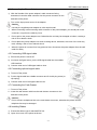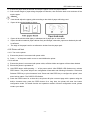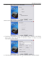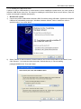
1
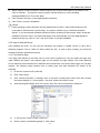
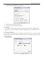
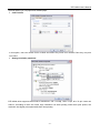
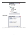
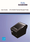
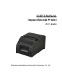
USER’S MANUAL Impact Receipt Printer BTP-M280 Shandong New Beiyang Information Technology Co., Ltd. BTP-M280 User’s Manual Contents 1 OVERVIEW ...............................................................................................................................................3 1.1 OUTLINE ...............................................................................................................................................3 1.2 FEATURES ............................................................................................................................................3 2 SPECIFICATIONS ....................................................................................................................................4 2.1 MAIN SPECIFICATION .............................................................................................................................4 2.2 CUTTER SPECIFICATION .........................................................................................................................5 2.3 PAPER SPECIFICATION...........................................................................................................................5 2.3.1 Continuous paper .........................................................................................................................5 2.3.2 Marked paper ...............................................................................................................................5 2.4 RIBBON SPECIFICATION .........................................................................................................................6 2.4.1 Ribbon model ...............................................................................................................................6 2.4.2 Demensions .................................................................................................................................6 2.5 PRINT AND TEAR-OFF POSITION .............................................................................................................7 2.5.1 Print position ................................................................................................................................7 2.5.2Tear-off position.............................................................................................................................7 3 OUTLINE AND PARTS .............................................................................................................................8 3.1 OUTLINE AND PARTS .............................................................................................................................8 3.2 LEDS AND BUZZER ...............................................................................................................................9 4 INSTALLING ...........................................................................................................................................10 4.1 UNPACKING ........................................................................................................................................10 4.2 MOUNTING THE PRINTER .....................................................................................................................10 4.2.1 Horizontal mounting ...................................................................................................................10 4.2.2 Wall-mounting (optional) ............................................................................................................11 4.3 CONNECTING TO A GROUND LINE ..........................................................................................................11 4.4 CONNECTING THE POWER ADAPTER ....................................................................................................12 4.5 CONNECTING USB SIGNAL CABLE ........................................................................................................12 4.6 CONNECTING OPTIONAL SIGNAL CABLE .................................................................................................12 -1- BTP-M280 User’s Manual 4.7 CONNECTING THE CASH DRAWER ........................................................................................................12 4.8 INSTALLING RIBBON.............................................................................................................................12 4.9 LOADING PAPER ROLL .........................................................................................................................13 4.9.1 Paper type..................................................................................................................................13 4.9.2 Loading/replacing paper roll .......................................................................................................13 4.10 PRINTER SELF-TEST ..........................................................................................................................14 4.10.1 Turn on the printer ....................................................................................................................14 4.10.2 self-test.....................................................................................................................................14 4.11 INSTALLING THE PRINTER DRIVER.......................................................................................................15 4.11.1 Typical setup.............................................................................................................................15 4.11.2 Advanced setup........................................................................................................................17 4.11.3 Installing the USB device driver................................................................................................19 4.12 HOW TO USE THE DRIVER..................................................................................................................21 4.12.1 User defined page ....................................................................................................................21 4.12.2 Parameter explanation .............................................................................................................22 5 MAINTENANCE......................................................................................................................................28 5.1 ROLLER CLEANING ..............................................................................................................................28 5.2 MARK SENSOR CLEANING ....................................................................................................................28 5.3 CLEAR PAPER JAM ...............................................................................................................................28 6 INTERFACE SIGNAL .............................................................................................................................30 6.1 USB INTERFACE .................................................................................................................................30 6.2 PARALLEL INTERFACE ..........................................................................................................................30 6.3 SERIAL INTERFACE ..............................................................................................................................31 6.4 ETHERNET ..........................................................................................................................................31 6.5 WLAN INTERFACE BOARD ...................................................................................................................32 6.6 POWER INTERFACE DEFINITION ............................................................................................................33 6.7 CASHDRAWER DEFINITION ...................................................................................................................33 7 TROUBLESHOOTING............................................................................................................................34 7.1 CUTTER ERROR TROUBLESHOOTING.....................................................................................................34 -2- BTP-M280 User’s Manual 7.2 PRINTER DOESN’T WORK .....................................................................................................................34 7.3 ERROR LED AND BUZZER....................................................................................................................34 7.4 PROBLEMS DURING PRINTING ..............................................................................................................34 7.5 PROBLEMS DURING USING DRIVER ......................................................................................................35 -3- BTP-M280 User’s Manual Declaration Information in this document is subject to change without notice. SHANDONG NEW BEIYANG INFORMATION TECHNOLOGY CO., LTD. (hereinafter referred to as “SNBC”) reserves the right to improve products as new technology, components, software, and firmware become available. If users need further data about this product or have any doubt about safety issues that might arise from using it, please feel free to contact SNBC or your local agents. No part of this document may be reproduced or transmitted in any form or by any means, electronic or mechanical, for any purpose without the express written permission of SNBC Copyright Copyright © 2007 by SNBC Printed in China Version 2.0 Trademarks SNBC registered trademarks are: Warning and Caution Warning: Items should be strictly followed to avoid damages to body and equipment. Caution: Items with important information and prompts for operating the printer. The quality control system of SNBC has been approved of the following certification. (DNV)ISO9001:2000 The environmental control system of SNBC has been approved of the following certification. (DNV)ISO14001:2004 -1- BTP-M280 User’s Manual General Safety Instruction Before installing and using the printer, please read the following items carefully: 1. Safety Instructions Warning: Do not touch the tear-off bar of the printer. Warning: The print head is at a high temperature during printing or just after operation, do not touch it and its peripherals for reasons of safety. Warning: The print head is an ESD-sensitive device. To prevent damage, do not touch either its printing parts or connecting parts. 2. Cautions 1) Install the printer on a flat and stable surface. 2) Reserve adequate space around the printer so that convenient operation and maintenance can be performed. 3) Keep the printer away from water source, direct sunlight, strong light and heat. 4) Do not use or store the printer in a place exposed to heat or fire, moisture or other pollution. 5) Do not place the printer on a place exposed to vibration or impact. 6) Avoid exposing the printer to condensation. In case of condensation, ensure it has been completely removed before turn on the power. 7) Connect the power adapter to an appropriate grounded outlet. Avoid sharing a single electrical outlet with large power motors and other devices that may cause the fluctuation in voltage. 8) The socket-outlet should be installed near the equipment and should be easily accessible. 9) Turn off the power if you do not use the printer for a long time. 10) Do not spill water or other electric substances (like metal) on the printer. If this happens, turn off the power immediately. 11) Do not allow the printer to start printing when there is no paper, otherwise the print head and platen roller will be damaged. 12) To ensure print quality and normal lifetime, use recommended or good quality paper and ribbon. 13) Shut down the printer when connecting or disconnecting interface connectors to avoid damage to the control board. 14) Do not disassemble the printer without guidance from a technician, even for the purpose of repair. 15) Keep this manual safe and at hand for reference purpose. -2- BTP-M280 User’s Manual 1 Overview 1.1 Outline The BTP-M280 is a 9-pin serial impact dot matrix receipt printer offering high quality, high speed, and stable performance. It is widely used in real-time printing on-site, such as POS system, kitchen and finance applications. The BTP-M280 can be connected with other devices via USB, parallel, serial, Ethernet and WLAN interface. USB interface is a fixed interface of the printer, and the other interfaces are optional interface of the printer. The BTP-M280 offers drivers and applications /2000/2003/XP/Vista. 1.2 Features ¾ Bi-directional printing. ¾ Two color printing ¾ Bi-directional carriage return ¾ Support multi-layer paper ¾ Easy paper loading ¾ Easy operation and maintenance. ¾ Support marked paper and continuous paper for print. ¾ Compatible with various wide paper. ¾ Cutter paper automatically ¾ Cash drawer control connector. ¾ Communication interface optional. ¾ Printer firmware updated online. -3- under WINDOWS 98/NT4.0 BTP-M280 User’s Manual 2 Specifications 2.1 Main Specification Item Specification Print mode 9-pin serial impact dot matrix Print speed Max. 4.7LPS (400 dots/line) Print width Max. 400(half dots)/200(full dots) Paper type Paper Character Data buffer Single layer Continuous paper or marked paper Paper width: 80±0.5mm, 76±0.5mm, 69.5±0.5mm, 57.5±0.5mm; Paper thickness: 0.06—0.085mm Multi-layer paper (1 original+1 copies) Paper width: 80±0.5mm, 76±0.5mm, 69.5±0.5mm, 57.5±0.5mm; Character type Font A: 9×9 Font B: 7×9 Paper thickness: 0.05—0.08mm, total thickness≤0.14 mm Chinese: 16×16 80/76mm 69.5mm 57.5mm Font A 33 CPL 30 CPL 25 CPL Font B 40 CPL 36 CPL 30 CPL Chinese 22 CPL 20 CPL 16 CPL Characters/line (Default) Character size (Default) Font A: 1.6×3.1mm Font B: 1.2×3.1mm Chinese: 2.7×2.9mm Characters/inch (Default) Font A: 13.3CPI Font B: 16CPI Receive buffer 4KB NV bit image data area 128KB User NV memory 8KB Ribbon specification Ribbon lifetime Chinese: 8.9CPI ERC-38 ribbon cartridge ERC-38(P) 4,000,000 characters ERC-38(B) 3,000,000 characters Black: 1,500,000 characters ERC-38(B/R) Red: 750,000 characters Communication interface USB (Fixed) + IEEE1284/RS-232/Ethernet / Wi-Fi interface (optional) Cash drawer connector 1~2 cash drawers Power supply DC 24V±5% average current 1.5 A Reliability Printing Mechanism lifetime 10,000,000 lines Print head lifetime 150,000,000 characters Cutter 1,000,000 times Operating temperature and humidity 5~45℃,20~90%RH (40℃) Storage temperature and humidity -40~60℃,20%~93%RH (40℃) Dimensions 160mm(W)×245mm(D)×145mm(H) Weight 2.9kg -4- BTP-M280 User’s Manual 2.2 Cutter specification Item Parameters Remark Cut method Sliding blade Cut time 600ms Time for one cutter action Cut interval 2s 30 cuts/minutes (Max.) Adapt Paper 65~100μm Normal paper with same thickness Operation voltage 24VDC Max. repose current 1.2A 24VDC Cutter lifetime 1,000,000cuts Under standard test conditions 2.3 Paper Specification 2.3.1 Continuous paper 1) Normal paper ¾ Paper width: 80±0.5mm/76±0.5mm/69.5±0.5mm/57.5±0.5mm ¾ Max. paper roll O/D: Φ83mm ¾ Paper roll core: ID Φ12.5mm; OD Φ16mm ¾ Paper thickness: 0.06—0.085mm 2) Multi-layer paper (1 original +1 copies) ¾ Paper width: 80±0.5mm/76±0.5mm/69.5±0.5mm/57.5±0.5mm ¾ Paper thickness: 0.05—0.08mm, total thickness≤0.14 mm Caution: Use only multi-layer paper (1 original + 1 copies) of which the original layer on contact the print head thicker than its under-layer. 2.3.2 Marked paper Besides the requirements of the continuous paper, marked paper should follow the following requirements: 1) Mark place y BTP-M280 printer reserves 8 positions for mark sensor, which can detect marks on either the front side or the reverse side of the paper. Position of the sensor is as shown in the figure. y The position of the mark sensor can be adjusted according to user’s need. The default position (Position 1) is on the right side of the paper on the front side (paper feed direction) as shown in the figure. 2) B/M size should meet the requirement as follow: y Mark width (L1): 5mm≤L1≤10mm y Mark height (L2): 12mm≤L2≤ paper width y Distance between marks (L3): 20mm≤L3≤500mm 3) The black mark’s reflectivity should be less than 15%, and the other part’s reflectivity should be more than 85%. There should be no image between the two marks, such as the advertisement etc. -5- BTP-M280 User’s Manual Caution: Do not paste the paper to the core. 2.4 Ribbon specification 2.4.1 Ribbon model Model Color ERC-38(P) Purple ERC-38(B) Black ERC-38(B/R) Black / Red 2.4.2 Demensions Unit:mm Caution: Please use the recommended EPSON original ribbon to ensure the printing quality and lifetime of the printer transmission part. -6- BTP-M280 User’s Manual 2.5 Print and Tear-off Position 2.5.1 Print position L1: Paper width L2: Print width L3: Print left margin L4: Print right margin According to the different paper width of the L1, the print width (L2) and the left/right margin (L3/L4) should be changed as below: Paper width (L1) Print width (L2) Left margin (L3) Right margin (L4) 80/76mm 63.4mm 6.8mm 5.8mm 69.5mm 57mm 6.8mm 5.7mm 57.5mm 47.5mm 6.8mm 3.2mm 2.5.2Tear-off position L1: About 21.5mm L2: About 34mm -7- BTP-M280 User’s Manual 3 Outline and Parts 3.1 Outline and Parts 1—Back cover 2—Tear-off bar 3—Front cover 4—POWER LED 5—ERROR LED 6—PAPER LED 7—FEED button 8—Power switch 9—Back cover latch 10—Communication interface 11—USB interface 12—Cash drawer connector 13—Power connector 14—Power pack(optional) 15—Cutter sliding Blade 16—Platen roller 17—Paper near end sensor regulator 18—Ribbon 19—Paper near end sensor 20—paper cabinet 21—Paper sensor 22—Mark sensor 23—Back cover sensor 24—Paper guide Functions of parts: 1) POWER LED(4) Indicate power status (on/off). When turning on printer, POWER LED is always on; when turning off printer, POWER LED is always off. 2) ERROR LED(5) Indicate all error status. Under normal conditions, ERROR LED is always off; under error conditions, ERROR LED will flash 3) PAPER LED(6) Indicate paper status of the printer. Under normal conditions, PAPER LED is always off; under paper end or paper near end conditions, it is always on 4) FEED button(7) ¾ Press the button while turning on the printer, a self-test page will be printed. ¾ In the normal status, press the FEED button for a short time, the printer will feed paper one line at a time. Under continuous paper mode, hold the FEED button, the printer will feed paper constantly. Under marked paper mode, it will feed paper to the next mark ¾ In HP error status, hold the FEED button for a long time, the printer will recover from HP error and start carriage verify check ¾ In cutter error status, hold the FEED button for a long time, the printer will recover from cutter error and start cut. ¾ In error status other than described above, press FEED button, the printer will have no action -8- BTP-M280 User’s Manual 5) Power switch(8) Turn on/off the printer. “O” is to turn off the printer; “—” is to turn on the printer. 6) Back cover latch(9) Catch back cover latch and pull it out to open the back cover. 7) Paper near end sensor(19) Detect the status of paper roll. If paper near end, the PAPER LED will on, the ERROR LED will flash and indicate user to replace paper. The printer will continue printing until the paper is end. 8) Paper sensor(21) Paper sensor is used to detect the printer with or without paper. 9) Mark sensor(22) When using mark paper, mark sensor is used to detect mark. 10) Back cover sensor(23) Back cover sensor is used to detect the position of the back cover. 11) Paper guide(24) There are three long slots at the bottom of paper cabinet. The paper guide could be plugged in different slot which is suitable for different wide paper, such as 76.5±0.5 mm, 69.5±0.5 mm, 57.5± 0.5 mm. Without paper guide, paper width of the printer is 80±0.5 mm. Caution: The paper guide is a necessary part of the printer for adjusting paper width, please keep it carefully. 3.2 LEDs and Buzzer The table below shows LEDs and buzzer in error status: Error Buzzer ERROR LED PAPER LED HP error Interval buzzing Interval flash Off Print head overheated Six sounds Six times Off Abnormal voltage Five sounds Five times Off Four sounds Four times Off Three times Off Three times Off Two times On Paper near end* One time On Pause to wait Off Flash Cutter error Back cover up Front cover up Paper end Three sounds (S-S-S) Three sounds (S-S-L) Two sounds Caution: The printer checks the print head temperature via thermal resistor. If the print head is extremely overheated, the printer will stop printing. -9- BTP-M280 User’s Manual 4 Installing 4.1 Unpacking When unpacking, you should check whether all parts are present and undamaged in accordance with the packing list. If any part is missing or damaged, please contact SNBC or your local agent. 4.2 Mounting the Printer BTP-M280 has two mounting modes: horizontal mounting and wall-mount. 4.2.1 Horizontal mounting The printer should be mounted on a flat and stable surface. For operation and maintenance, we suggest you reserve space below the printer to ensure its reliability and easy operation. ¾ BTP-M280 power supply external: ¾ The height of printer will increase 38.5mm while using power pack: - 10 - BTP-M280 User’s Manual 4.2.2 Wall-mounting (optional) Wall-mount is an optional function. The wall-mount mode is shown as below. 1) Two 50mm-deep holes should be made with a hammer-drill in a suitable wall, of the sizes shown below. 2) Insert plastic plugs and screws into Φ6 holes and ensure that the end sides of the plugs are flush with the surface of the wall. 3) Put the screws into plastic plugs with screwdriver, keeping a distance of 10mm between screw head and wall side. 4) Install the printer according to the arrowhead. Caution: In case of wall-mount, the printer must be oriented upwards. The hook on the wall should be firmly positioned to avoid printer damage or risk of falling. 4.3 Connecting to a ground line Printer housing should be grounded. Please ensure the material is AWG18 or equivalent. 1) Turned off the printer. 2) Loosen the ground line screw and connect it to back case of printer with screwdriver. - 11 - BTP-M280 User’s Manual 4.4 Connecting the Power Adapter 1) With the flat side of the power adapter’s cable connector facing downward, insert the cable connector into the power connector on the backside of the printer. 2) Turn on the input power source of the adaptor. Caution: Use only the supplied power adapter or other equal model. When connecting or disconnecting cable connector of the power adapter, you should pull on the connector, not pull on the cable by force. Do not pull on the power adapter cord. Otherwise the cord may be damaged or broken, causing a risk of fire or electric shock. Do not place the power adapter cord near a heating device, otherwise, the cover of the cord may melt, causing a risk of fire or electric shock. When the printer is not used for a long period of time, disconnect the power adapter from the wall outlet for safety. 4.5 Connecting USB signal cable 1) Ensure the printer is turned off. 2) As shown the figure below, put the USB signal cable into the suitable USB interface. 3) Connect other end of USB signal cable to host. 4.6 Connecting optional signal cable 1) Turned off the printer. 2) Put the signal cable into suitable connector and fix it with plug screw (or clip spring). 3) Connect other end of the signal cable to host. 4.7 Connecting the Cash Drawer 1) Turned off the printer. 2) Insert the cash drawer cable into the cash drawer connector on the backside of the printer. Caution: Do not connect a telephone line to the cash drawer connector; otherwise the printer and the telephone line may be damaged. 4.8 Installing Ribbon 1) Ensure that ribbon type is standard ERC-38. 2) Open front cover of the printer as shown. - 12 - BTP-M280 User’s Manual 3) Turn the ribbon knob two or three times according to the mark to tighten the ribbon. 4) Refer to the figure to install ribbon to the correct position. 5) Turn the ribbon knob two or three times according to mark to tighten the ribbon again. Caution: The print head will become hot during printing. To avoid harm or injury, please do not replace the ribbon until it cooled down. Ribbon should be mounted between print head and paper, without folds or drapes. 4.9 Loading Paper Roll 4.9.1 Paper type Before loading roll paper, you should confirm the type of the paper can be used for printer. The default paper type is continuous paper. If marked paper will be used, please contact your local dealer for assistance. 4.9.2 Loading/replacing paper roll 1) Press back cover button to open the back cover. 2) Hold the hole in the paper guide to install or offload it. When using 76mm, 69mm, 57mm width paper roll, user needs to insert paper guide vertically into a suitable location. When using 80mm width paper roll the paper guide doesn’t need to be placed into the printer, but please keep it safely in case of using in the future. Notes: Without paper guide: 80±0.5mm With paper guide: A:76±0.5mm B:69.5±0.5mm - 13 - C:57.5±0.5mm BTP-M280 User’s Manual 3) Ensure the paper head is trimmed and drop the paper roll into the paper cabinet. 4) Pull a certain length of paper along the paper-out direction, then close the back cover and tear off the surplus paper. Caution: User should adjust the paper guide according to the width of paper roll being used. Paper roll should be loaded as shown: Paper roll should be rolled tightly to eliminate risk of paper jam or other faults. Paper should be loaded in paper cabinet firmly and straight; otherwise, paper auto-load and print will be affected. The edge of the paper head is not allowed to deviate from the paper path. 4.10 Printer self-test 4.10.1 Turn on the printer 1) Ensure the printer is connected with power cable. 2) Press “—” of the power switch to turn on and initialize the printer. 4.10.2 self-test 1) Ensure the printer is connected with power cable; sufficient ribbon and paper roll have been loaded. 2) Ensure the printer is powered off. 3) Hold FEED button while pressing “—” of the power switch. After ERROR LED flashes once, release FEED button. The printer will print out configuration information and following information: “Press and Release FEED key to print characters” and “Press and Hold FEED key to configure the printer”, then enter hold-on status. The PAPER LED flashes. 4) Press the FEED button for a short time, the printer will print a second page with a pattern using the built-in character sets; press the FEED button for a long time, the printer will enter into button configuration mode. For detail function and operation method of button configuration mode, please contact your dealer. - 14 - BTP-M280 User’s Manual 4.11 Installing the Printer Driver BTP-M280 printer offers the drivers under Windows 98/Windows NT4.0/Windows 2000/Windows XP/Windows server 2003/Windows Vista with the installing steps as below. 4.11.1 Typical setup 1) Run “Setup.exe” in the driver installing package and read the relative software licensing protocol carefully. If you accept it, please click “I Accept”, then click “Next” button. 2) Select the model and the name of the printer to be installed. If you want to set it as default printer, please select “Set As Default Printer”, then click “Next” button. - 15 - BTP-M280 User’s Manual 3) Select the setup type “Typical”, then click “Next” button. Select the current system type and click “Next” button. 4) Set printer port. The default port is “LPT1”. User can install it based on actual port. Under Windows NT4.0 or above, please select “BYCOMx” for serial driver (x equals to 1,2,3,4,5,6,7 or 8). Click “Finish” button to end the installation. 5) If the current system is Windows 98/Me, click “Yes” in the pop-up window to restart the computer. - 16 - BTP-M280 User’s Manual 4.11.2 Advanced setup Advanced setup is mainly used for users who have special requirements for printer drivers. Compared with typical setup, advanced setup can support the divers installation of Multi USB printers and has the function of printer driver mode setting. Setup steps are as follows. 1) Run “Setup.exe” in the driver installing package and read the relative software licensing protocol carefully. If you accept it, please click “I Accept”, then click “Next” button. 2) Select the model and the name of the printer to be installed. If you want to set it as default printer, please select “Set As Default Printer”, then click “Next” button. - 17 - BTP-M280 User’s Manual 3) Select the setup type “Advanced”, then click “Next” button. 4) Select the current system type and click “Next” button. 5) Set driver mode and printer port of the printer. Default settings are: port is "LPT1" as default port and supporting Multi USB printers. Click "Finish" to end the installation. 6) If the current system is Windows 98/Me, click “Yes” in the pop-up window to restart the computer - 18 - BTP-M280 User’s Manual 4.11.3 Installing the USB device driver If printer is using a USB interface to communicate, before installing the printer driver, the user needs to install the USB device driver first. The steps for installing the USB device driver are as follows: (Take XP system as example for detailed introduction) ¾ 1) Windows XP system Connect the printer USB interface with idle USB PC interface using USB cable. System will recognize USB device automatically and popup "Add New Hardware Wizard". Select "Install from a list or specific location", then click "Next". 2) Select "Search for the best driver in these locations" and "Include this location in the search", then Click "Browse..." to browse the driver document. Default directory is “Driver installing package\USBDRV2.20. Then click "Next". - 19 - BTP-M280 User’s Manual 3) Click "Continue Anyway" on the digital signature interface. 4) Click on "Finish" to end the installation. ¾ Windows 98/Me system 1) Connect USB interface of the printer with idle USB interface of the PC Using USB cable. System will recognize USB device automatically and popup "Add New Hardware Wizard", then click "Next". 2) Select "Search for the newest driver for your device", then click "Next". 3) Select "Specify a location", click "Browse" button to browse the driver document. Default directory is “driver installing package\USBDRV2.20”, then click "Next". 4) The wizard will indicate the device driver’s name that have found. Then click "Next". 5) Click "Finish" to end the installation. ¾ Windows 2000 system 1) Connect USB interface of the printer with idle USB interface of the PC Using USB cable. System will recognize USB device automatically and popup "Add New Hardware Wizard", then click "Next". 2) Select "Search for the best driver for your device", click on "Next" 3) Select "Specify a location", then click "Next". 4) Click "Browse" button to browse the driver program. Default directory is “Drivers installing package\USBDRV2.20. 5) The wizard will indicate the device driver’s name that have found. Then click "Next" 6) Click "Yes" on the digital signature interface. 7) Click "Finish" to end the installation. ¾ Windows Server 2003 system 1) Connect USB interface of the printer with idle USB interface of the PC Using USB cable. System will recognize USB device automatically and popup "Add New Hardware Wizard". Select “Install from a list or specific location”, then click "Next". - 20 - BTP-M280 User’s Manual 2) Select "Search for the best driver in these locations" and "Include this location in the search", then Click on "Browse..." to browse the driver program. Default directory is “Driver installing package\USBDRV2.20. Then click "Next". 3) Click "Continue Anyway" on the digital signature interface. 4) Click "Finish" to end the installation. Caution: Under operating systems Windows XP and Windows Server 2003, if other USB interfaces of PC connected to USB interface of printer firstly. The system will also Pop-up "Add New Hardware Wizard". If you have already installed USB device driver according to above steps, select "Automatic installation" and click "Next", the wizard will search driver automatically, then the digital signature interface will pop-up. Click on "Yes", and click "Finish" to end the installation. 4.12 How to Use the Driver After installing the driver, you can print all characters and images in WORD, EXCEL or other file in Windows programs, That is ‘’What You See Is What You Get’’. In order to print normally, you should set the page and select parameters properly. 4.12.1 User defined page If the page size defined by the driver can not meet user’s requirement, user can define the page size; under Window 98 system, user defined page can be defined via page settings. But under Windows NT4.0/ Windows 2000/ Windows XP/ Windows server 2003/Vista, user cannot define page size via page settings. The following steps introduce how to define page size (take Windows XP system as an example): 1) Ensure the system running normally. 2) Click “Start” button. 3) Click “Printers and faxes” in “Settings” item; or first click “Control panel” button, then click “Printers and other hardware” in “Control panel”, next click “Printers and faxes” button. 4) After selecting BTP-M280, click “File” menus, then click “Service Properties” submenus 5) In “Forms” item, select “Create a new form”. 6) Define a name of self-defining paper in “Form name”. - 21 - BTP-M280 User’s Manual 7) Take metric CM as measurement units. Define paper width, length, right/left and up/down margin of the printing area according to user’s own need. 8) Click “Save Form” button to save the form. 9) Click “Apply” button to finish paper self-definition Caution: Before setting user defined page, please ensure that the printer driver has been installed properly. In application, you can select the page in varieties of official software such as WORD, EXCEL and so on. 4.12.2 Parameter explanation The driver offers cut mode, paper type and cash drawer functions for users to use. Users can configure the parameters according to their needs. Take Windows XP system as an example to describe how to set the driver parameters. ¾ Setting paper type - 22 - BTP-M280 User’s Manual Optional paper type: roll paper and marked paper ¾ Color choose In this option, user can choose Color or black and white. Only when user chooses Color they can print two colors. ¾ Setting resolution parameter BTP-M280 driver supports three kinds of resolutions: 160 x 144 dpi, 160 x 72 dpi, 80 x 72 dpi. Users can select it according to their own need. High resolution has clear printing while lower print speed; low resolution has higher print speed while less clear printing. - 23 - BTP-M280 User’s Manual ¾ Single/ Bi-directional print setting Set single/bi-directional print settings via this option. ¾ Operation option User can set different setting of page via this option: start of document, start of page, end of page, end of document. - 24 - BTP-M280 User’s Manual ¾ Document setting option User can set parameters via this option on the start of document, end of document, start of page and end of page; Cash drawer (Cash drawer1, Cash drawer2, Cash drawer1+2,print messenger Herald) and Cash drawer pulse width;Buzzer (Buzz 200ms, 600ms, 1s, 2s, 4s); paper feed;paper cut (paper cut by hand, partial cut, full cut), print Logo bitmap. ¾ Utility User can set control font and print self test page via this option, at the same time user can set user-defined page size. - 25 - BTP-M280 User’s Manual ¾ Download User can download firmware and Logo via this option. ¾ Font User can select driver supported font and font size via this option. - 26 - BTP-M280 User’s Manual ¾ Version information User can see the printer driver version information via this option. - 27 - BTP-M280 User’s Manual 5 Maintenance Caution: For daily maintenance be sure the printer is turned off. Do not use gasoline, acetone or other organic liquids to clean any parts of the printer. When cleaning the sensor, please leave the printer off until the alcohol completely dried. Recommended maintenance cycle shall be no longer than a month. 5.1 Roller cleaning Steps for roller cleaning are as follows: 1) Turn off the printer power. 2) Pull the latch to open the back cover, as shown in the figure: 3) Keep the back cover open, clean the dust and duty on the platen roller using a soft cotton cloth with little moderate cleanser. 4) Wait until the cleanser is completely evaporated then close the back cover and finish roller cleaning. 5.2 Mark sensor cleaning If the printer does not identify the mark effectively, you should clean the mark sensor: Steps for mark sensor cleaning are as follows: 1) Turn off the printer. 2) Pull the latch to open the back cover of the printer. 3) Keep the back cover open, clean the dust and dirt off the mark sensor using a soft cotton cloth with a little alcohol. 4) Wait until the anhydrous alcohol completely evaporated then close the back cover and finish mark sensor cleaning. 5.3 Clear paper jam When the printer in one the following situations, you should clear the paper jam: ¾ Paper can not get out normally. ¾ Excessive noise occurs with paper feeds. Steps for cleanup paper jam are as follows: - 28 - BTP-M280 User’s Manual 1) Turn off the printer 2) Pull the latch to open the back cover of the printer 3) Check if there is any paper in the paper path, if necessary, clear the jammed paper. 4) Close the back cover and finish clearing paper jam. - 29 - BTP-M280 User’s Manual 6 Interface Signal The BTP-M280 can be connected with other devices via USB, parallel, serial, Ethernet and WLAN interface, USB interface is a fixed interface of the printer and other interfaces are optional. 6.1 USB interface The printer USB interface supports USB1.1 protocol, of which the outlet is USB A type. Interface signal is defined as below: Pin Lead 1 VCC 2 DATA- 3 DADA+ 4 GND 6.2 Parallel interface The parallel interface of printer is bi-directional and supports the BUSY/ACK handshake protocol and the nibble protocol. The interface outlet is 36PIN CENTRONICS. Pin Signal resource Signal definition Pin Signal resource 1 H nStrobe 19 Signal Ground 2 H Data 0 (Least Significant Bit) 20 Signal Ground 3 H Data 1 21 Signal Ground 4 H Data 2 22 Signal Ground 5 H Data 3 23 Signal Ground 6 H Data 4 24 Signal Ground 7 H Data 5 25 Signal Ground 8 H Data 6 26 Signal Ground 9 H Data 7 (Most Significant Bit) 27 Signal Ground 10 P Ack 28 Signal Ground 11 P Busy 29 Signal Ground 12 P PError 30 Signal Ground 13 P Select 31 H 14 H P nInit nAutoLF 32 15 Not defined 33 Signal Ground 16 Logic Gnd 34 Not defined 17 Chassis Gnd 35 Not defined Peripheral Logic High 36 18 P H Caution: Signal definition H means signal source from a host, and P means signal source from printer. - 30 - nFault nSelectIn BTP-M280 User’s Manual 6.3 Serial interface The printer serial interface is compatible with RS-232 standard, of which the outlet is 25PIN female D type. Pin Signal definition 1 2 3 4 5~6 7 8~19 20 21~25 Frame ground TXD RXD RTS Not connected Signal Ground Not connected DTR Not connected User can query interface settings status via a printing configuration sample. The default setting is as follows: Baud rate: 9600bps Data bit: 8bits Parity bit: None Stop bit: 1 bit Flow control: DTR/DSR 6.4 Ethernet 1) Interface features ¾ Support of 10BASE-T communication ¾ Compatible with Ethernet II standard frame type. ¾ Indicator shows network connecting status and data transmission status ¾ Supports 9100 port print ¾ Supports status back ¾ Supports parameter configuration ¾ Supports firmware update on-line ¾ Supports printer status query and interface module maintenance based on HTTP. 2) Protocols Supported: ¾ IP ¾ ARP ¾ ICMP ¾ TCP ¾ UDP ¾ DHCP ¾ TFTP ¾ HTTP - 31 - BTP-M280 User’s Manual 3) Electrical features ¾ Output signal: The available differential mode voltage is more than 450mV,and peak voltage is less than 13V. The common mode AC peak voltage is less than 2.5V. ¾ Input signal: The differential mode voltage that more than 160mV is identified as available signal 4) Interface shall use RJ45 outlet which accord with 10BASE-T standard of IEEE802.3. 5) Interface signal definition Pin Signal name Instruction 1 TX+ Data transmission+ 2 TX- Data transmission- 3 RX+ Data receiving+ 4 NC Reserve 5 NC Reserve 6 RX- Data receiving- 7 NC Reserve 8 NC Reserve 6.5 WLAN Interface Board 1) 2) Interface features ¾ Supports 802.11b, 802.11g protocol ¾ Supports 9100 port printing,LRP printing ¾ Supports status back ¾ Supports parameter configuration ¾ Supports Firmware update on-line ¾ Supports HTTP protocol Protocols supported ¾ IP ¾ ARP ¾ ICMP ¾ TCP ¾ UDP ¾ DHCP ¾ TFTP ¾ HTTP For detailed specification, please refer to User Manual Of WLAN Interface Module. - 32 - BTP-M280 User’s Manual 6.6 Power interface definition 1) Pin definition 1: Positive pole (+24V) 2: Cathode(GND) 3: NC 2) Interface type Printer end should use: Unetop DC-002 or equivalent product. User end should use: Unetop DP-002 or equivalent product. 6.7 Cashdrawer definition 1) Electrical features ¾ Driving voltage: DC 24 V ¾ Driving current: Max 0.8 A (within 510 ms) ¾ Cash drawer status inspection signal: “L” = 0~0.5 V “H” = 3~5 V 2) Cash drawer interface outlet uses RJ11 6P connector. 3) Interface signal definition Items Signal Functions 1 FG Frame Ground 2 3 DRAWER 1 Cash drawer 1 driving signal DRSW 4 VDR Cash drawer status test signal Cash drawer driving power 5 6 DRAWER 2 Cash drawer 2 driving signal GND Circuit share ground Caution: Do not connect or disconnect signal cable when printer power is on. Signal cable should be far away strong current. Signal cable should be far away from strong current sources. - 33 - BTP-M280 User’s Manual 7 Troubleshooting In case of printer fault, consult this section for solutions and advice. If you do not find a solution in this section, please contact your local dealer for assistance. 7.1 Cutter error troubleshooting When cutter fails to recover due to paper jam or sudden off-line status, perform the following actions: 1)Turn off power of the printer. 2)Pull the latch to open the back cover of the printer. 3)Power on the printer, the cutter will be reset automatically. Caution: To avoid injury, please do not touch the sliding blade of the cutter when printer is power on. 7.2 Printer doesn’t Work Problems LED is off and the printer doesn’t work Possible causes Solution Make sure that printer cable has been connected properly on both Printer power is off ends. Printer is not turned on Turn on printer. Circuit is damaged Contact your local dealer. 7.3 Error LED and Buzzer Problems Error LED flashes and buzzer beeps Possible causes Paper near end Replace roll paper. Paper end Replace roll paper. Back cover up Close back cover. Cutter error Refer to 7.1 Cutter error troubleshooting. Input voltage abnormal Turn off printer power and check input voltage. Print head overheated Solution Turn off printer power and wait until the print head turn to normal temperature. If ribbon is damaged, replace ribbon. HP error Press & hold FEED button or power on the printer again. 7.4 Problems during Printing Problems Printout is light and not clear Always feed paper in printing Possible causes Ribbon ink is out Replace ribbon. Confirm if paper type matches with the paper used Printout is not clear or dirty Print head or paper feed platen is dirty Paper cannot be fed normally Paper jam Horizontal printout is missing Solution Replace with correct roll paper. Clean print head or paper feed platen. Open back cover to check paper path and remove paper jam. Ribbon is damaged Replace ribbon. Print head error Contact your local dealer. - 34 - BTP-M280 User’s Manual 7.5 Problems during Using Driver Problems Printer can not print when using USB interface Print mass code with serial interface Possible causes Device driver is not installed. Solution Refer to 4.11.3 Installing the USB device driver. Print a self-test page to confirm serial Configure serial parameter incorrectly configuration of the current printer and configure it correctly. Can not print two color Parameter of the printer not correct Used one color ribbon Black mark fails to be positioned normally Page settings are not correct Configure two color printing please refer to 4.11.2 Parameter explanation. Change to two color ribbon. Select correct paper type in the document setting option. Extend the overtime of serial and Printer can not work normally under serial, parallel interface Overtime setting is too short parallel communication referring to the help file in the package. Current port is occupied. - 35 - Close other programs which use the port.