1
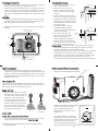
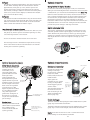
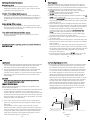
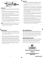
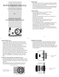
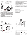
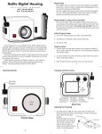
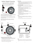
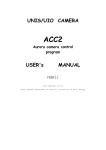
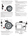
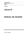
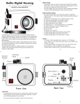
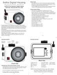
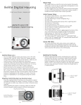
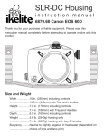
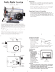
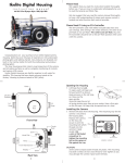
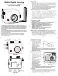
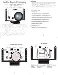
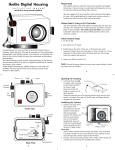
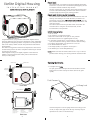
Ikelite Digital Housing
instruction
manual
Please Read
We suggest that you read this instruction booklet thoroughly
before use. If you are new to underwater photography, be sure
to read the General and Photo Tips sections.
We also suggest that you read the camera manual thoroughly
to have a full understanding of where each camera control is
located and what function each control provides.
#6148.11 for Canon SX110 IS, SX120 IS
Please Read If Using an EV-Controller
The EV-Controller used with Ikelite DS Substrobes has two user
settings. One setting is for strobe selection, the other is for
pre-flash or non pre-flash. This camera uses pre-flash, thus the
EV-Controller should be set to the pre-flash position when used
with this camera.
The camera does not emit a pre-flash when used in the “M”
manual mode. If using the “M” manual mode, set the
EV-controller to non-pre-flash.
Initial Camera Setup
Congratulations on your purchase of an Ikelite Digital Camera
Housing. Ikelite has over 45 years of experience in the underwater
photographic and lighting market. Our products are designed and
built in the USA by Ikelite for both the professional and amateur
photographer.
The clear housing permits instant visual inspection of the camera
and all sealing surfaces as well as complete monitoring of controls
and camera LCD screens.
Ikelite Digital Housings are slightly negative in salt water for
stability. This housing has been water pressure tested at the
factory to 200’ (60m).
Zoom Dial
1.
2.
3.
4.
5.
5.
6.
7.
8.
Set ISO to 80.
Set camera to “A” Aperture priority.
Raise the camera flash to it’s open or “UP” position.
Set Flash to forced “On” (lightning bolt in LCD).
In the Flash Control Menu > Flash Settings > Flash Mode >
Auto, should be the setting, which is also the default setting.
For Macro photography, set aperture to f7.1 or 8.0.
Set White Balance to “Auto”.
Set Image Quality to “Superfine” and Large “L”.
Set Metering to “Center Weighted Avg.”.
NOTE: Make sure that the camera flash is in the “up” or “raised”
position before closing your housing with the camaera inside.
2
Opening the Housing
Mode Dial
1. Lid Snaps have a Lock.
To open, push each Lid Snap Lock forward and lift as shown.
Keep pressure on the Lid Snap so that it does not fly open
quickly.
Shutter
Release
Lid
Snap
Lid
Snap
Lens
Port
Push Forward
Front View
Lid Snap Lock
Power Button
A
B
C D
E
H
F G
I
J K
[A] Print/Share
[B] Playback
[C] Face Selector
[D] Exposure
[E] ISO/Jump
[F] Macro
[G] FUNC./SET
[H] Flash/Control Dial
3
Back View
[I] Continuous
[J] Display
[K] Menu
Lift
Some lid snaps have a lot of spring tension once they go over
center, so keep a firm grip on the lid snap. Lid snaps may be
opened one at a time or simultaneously.
4
Installing the Camera
1. Pull out on each housing control until it stops. This will get the
controls out of the way for installing the camera.
2. Remove the back from the housing. The mounting tray for the
camera is secured to the housing back. Position the camera on
the tray, and using a coin or screwdriver (preferred), secure it
with the mounting bolt which threads into the camera’s tripod
socket.
CAUTION:
Some camera tripod socket threads are plastic. The mounting
tray bolt is metal. Do not cross thread or over tighten as you
may damage the camera tripod socket threads.
3. RAISE the camera flash. This must be done before closing the
housing.
RAISE FLASH before
closing housing
O' Ring
PowerShot SX110 IS
Canon
Lid
Hook
10x
OPTICAL
ZOOM
9.0
MEGA
PIXELS
Mounting
Tray
Mounting Bolt
5
Closing the Housing
housing back
1. Place housing face down in your
lap or on flat surface.
2. Check to see that there is an
o-ring on the housing back and
that it is clean and in its proper
location.
3. Guide the back into the housing
o-ring
front. The o-ring should touch the
housing all the way around. There
should be an even gap all the way
around between the housing and
the housing back.
4. Lift the lid snaps so they are
housing back
extended and place each lid
snap into the corresponding hook
on the housing back.
5. To close the housing, push
even gap
all 4 sides
down on the lid snaps until
they snap into place . Lid
snaps on opposite sides of the
o-ring
housing should be closed at the
same time. Be sure they are down
far enough to engage the lock.
Double check - Once the housing is closed, check the o-ring seal.
Check the gap between the housing back and the housing. It
should be even all the way around the housing.
Look through the clear plastic back at the o-ring. You should see
a darkened area where the o-ring is compressed against the
housing back. If you do not see an even black compression seal
all the way around the back, open the lid snaps, reseat the
housing back and close the lid snaps. Visually check the seal again.
6
CAMERA / MOUNT
Checking Controls
Once the housing has been closed, make sure the housing
controls line up with the corresponding camera controls. If the
housing controls are misaligned slightly, make sure the camera
hold down bolt has been tightened down firmly so the camera
is flat against the tray.
Diffuser and Deflector Installation
Housing shown with Deflector installed.
Deflector
Turn Camera On
Turn the camera on and operate each of the housing controls to
get a feel for using the camera in the housing. Take a few pictures
above water with the camera in the housing.
Zoom Control
(NOTE:) After you have used the
housing's zoom control, it must be
returned to the center position to
disengage. If the housing zoom
control is pushing the zoom lever
in either direction, you may not
be able to take a picture or access
any other function because the
camera is receiving a signal from
the engaged zoom control.
Using Flash
+
-
Engaged
-
+
Center Position
Disengaged
Using the Camera’s Built-in Flash.
If you do not have an external flash, the camera’s built-in flash
can be used. See Diffuser instructions (Page #8 & #9).
NOTE: The camera’s built-in flash cannot be used with optional
Wide-Angle lenses.
7
A diffuser and deflector are included
with the housing. The diffuser is
white transparent plastic. The
deflector is also white, but is not
transparent.
Diffuser/Deflector
material
To install the diffuser or deflector,
Spring
spread the port clamp at the spring
end and slide over the lens port. The
white plastic should be placed in
Spread to Install
front of the camera flash. The port
clamp should be pushed back against the front of the housing.
8
Port Clamp
Diffuser
The diffuser should be installed when using the camera’s built
in flash. When shooting with the camera’s built-in flash at
approximately 2 feet (0.6 m) or less, the lens port on the
housing may block a portion of the light from the camera’s
built-in flash, creating a shadow in the lower area of the photo.
If this occurs, zoom the lens slightly to eliminate the shadow.
(You can test this above water)
Deflector
The deflector should be installed when using an external strobe
such as the DS51 or DS161 Substrobe with an EV Controller. The
deflector will redirect the camera’s flash to the EV Controller
which controls the external DS strobe’s output.
Lens Port and Accessory Lenses
Treat the glass in the lens port as a camera lens. After use, rinse
and gently dry the lens port to avoid water spotting. To clean,
use a mild soap solution or lens cleaner.
Do not use alcohol or window cleaner on the Lens Port.
The Housing Lens Port is threaded to accept 67mm accessory
lenses. These lenses are NOT recommended for use with this
housing due to extreme vignetting
Optional Accessories
Using Ikelite DS Digital Strobes
For the best underwater photographic results, we recommend
adding an external DS-digital strobe connected to the housing with
a #4103.51 TTL Sync Cord and a SA-100 Ball/socket arm (Page #11).
Ikelite DS series Substrobes are industry favorites for their warm,
even coverage and lightning fast recycle time. Being farther from
the camera lens, the optional DS Substrobe aids in reducing the
illumination of particles in the water and helps to eliminate
backscatter. When used in conjunction with the EV-Controller, the
DS51 Mode switch is set to the TTL setting and the EV-Controller
provides ten power settings in half-stop increments.
Ikelite Substrobe DS51
The compact, lightweight and affordable Substrobe DS51 is well
suited for general and macro photography. This strobe can easily
switch between TTL/Auto and any of the six (6) manual power
settings for complete control over lighting the subject. The strobe's
wide-angle diffuser increases the angle-of-coverage up to 80
degrees.
ikelite
SUBSTROBE
DS
51
Substrobe
DS51
ikelite
10
9
Optional Accessories (cont.)
Optional Accessories (cont.)
DS161 Movie Substrobe
The DS161 Movie Substrobe
Batt
combines all of the
w/Lite
Off
functionality of our
On
renowned DS160 with a
On
powerful 500 lumen LED
video light. Three
super-bright LEDs are
arranged behind a special
optical element to provide
DS161 Movie
45 degrees angle of coverage Substrobe
free of hotspots. The DS161
flash covers the equivalent
of an 18mm lens or 100
degrees w/diffuser installed.
It is the ideal choice when
using wide angle lenses
greater than 80 degrees. It
also features a 1.5 second
recycle time and 225 flashes
per full charge.
SOS
TTL Full
EV Manual Controller
-1
3
-2
Ready Light
2
-3
1
-4
w/Lite
DS
ikelite
Simply point the
Controller at your camera
housing for dependable
strobe triggering by the
camera strobe.
SA-100 Ball/Socket
Arm #4086.61
connect to
DS-Substrobe
#3944.54 Substrobe DS51 package includes #4086.61 Arm System
(page #11), and EV Manual Controller.
#9571.3 Extended
Stem Mount (included
with SA-100
Ball/Socket arm)
11
The Controller attaches to
the strobe and mounts
near the housing on the
#9571.3 Extended Stem
Mount (Page #11).
mount to
Extended
Stem Mount
(page #11)
Strobe Packages
Strobe Arms
The top of the rubber handle
utilizes Ikelite’s Quick-Release
Arm, available as the
recommended SA-100 Arm
system (pictured).
EV-controller
Provides 10 manual power
settings in half-stop
increments for SubStrobe
DS50, DS51, DS80,
DS125, DS160, DS161, and
DS200 models.
Fuel
Guage
#3945.03 Substrobe DS161 package includes #4086.61 Arm System
(page #11), 1.5 hour Smart Charger, and EV Manual Controller.
Note: DS Strobes must be set to “TTL” to utilize the manual
power settings on the EV Manual Controller.
12
Optional Accessories (cont.)
Back o-ring #0110
O-rings last for several years if properly maintained. (See
maintenance section). Always carry a spare o-ring in case the
original becomes damaged or lost.
UR/Pro Filter (Blue Water) #6441.41
The UR/Pro underwater color correcting filter is designed to
restore some of the warm colors filtered out by the water. For
available light use only and not recommended for use with
flash.
Green Water Filter #6441.81
Enhances contrast and alters the color of green water to give
our subject a rich, natural tone. For available light only and not
recommended for use with flash.
Tray with Dual Release Handles #9523.32
Dual Tray and Release Handles are required to mount two
external Substrobes.
Complete information regarding optional accessories available at
www.ikelite.com
13
Lubricants
1. Ikelite provides silicone lubricant with the housing. We recommend
you use only Ikelite lubricant on Ikelite products as some other
brands may cause the o-ring to swell and not seal properly.
2. Use only enough lubricant to lightly cover control shafts and
o-rings. Wipe off any excess lubricant with a clean cloth.
Lubricant is not a sealant, it is used to reduce friction. Excessive
lubricant can collect sand and dirt which may interfere with
proper sealing.
CAUTION
Never use spray lubricants as the propellant ingredient can
cause the plastic housing to crack.
Control Maintenance
Ikelite controls are designed to provide years of reliable service
with minimal maintenance.
1. Push button controls require no maintenance other than rinsing
in fresh water after saltwater use. If a push button control
becomes difficult to push or if it sticks when depressed, soak the
housing in luke warm fresh water. After a few minutes, operate
the push button. If this does not correct the problem, return the
housing to Ikelite for maintenance.
2. Some of the controls have long shafts. These controls can be
pulled out, exposing the shaft (see diagrams A and B on pages
#16 & #17).
To lubricate the control, gently pull on the knob until the
stainless steel shaft is exposed. Lightly lubricate the shaft, then
move the shaft in and out several times. This will lubricate the
x-ring in the Ikelite control gland. This should be done before
using the housing after a prolonged storage period, or once a
week when the housing is in constant use.
15
Maintenance
The Ikelite Digital Housing should be given the same care and
attention as your other photographic equipment. In addition to
normal maintenance, we recommend that the housing be returned
to Ikelite periodically to be checked and pressure tested.
1. Do Not leave the camera and housing in direct sunlight for
prolonged periods. Heat may damage the camera.
2. Do Not ship the camera in the housing.
3. Before using the housing, always check the tightness of the set
screw in each control knob.
Check each control gland penetrating the housing to make sure
they are tight. There is a slight chance that either could vibrate
loose during travel.
4. Keep the back o-ring clean and lightly lubricated. To lubricate,
remove the o-ring from the back. Put a small amount of lkelite
lubricant on your fingers. Pull the o-ring through your fingers
to apply a light coating of lubricant. Only apply enough
lubricant to make the o-ring feel slick. Do Not stretch the
o-ring. This light coating of lubricant will help to keep the
o-ring from drying out and will help to show a dark sealing
line when the housing back is properly sealed.
5. Keep the area where the o-ring fits and the sealing surface of
the housing clean.
6. Rinse the housing exterior thoroughly in fresh water after each
salt water use. Dry with a soft cloth. Dry lens port to eliminate
water spotting.
After several uses in salt water, soak the housing exterior in a
mild soap solution, rinse and dry, before storing. When storing
the housing, remove the back o-ring, lightly lubricate, and place
in a plastic bag. Place the plastic bag with o-ring inside the
housing for safe keeping.
7. If removing a housing push button, Do Not re-use the E-clip.
Contact Ikelite for replacement E-clips (part #0319.12).
14
Control Maintenance Cont.
3. Some of the controls have a short shaft and cannot be pulled
out exposing the shaft for lubrication. In the unlikely event
one of these controls sticks or becomes difficult to operate
you can remove the control from the housing and lubricate it,
or return the housing to Ikelite for maintenance. To remove
the control (Diagram A), loosen the set screw in the knob
(allen wrench required); remove the knob. If there is salt or
dirt build-up on the exposed control shaft, clean the shaft.
Open the housing and gently slide the control shaft out of the
control gland. Clean and lightly lubricate the shaft, including
the end of the shaft. Slide the shaft back into the control
gland and gently slide it back and forth a few times without
fully removing the shaft from the gland. Replace the knob
noting the flat area on the shaft. The set screw in the knob
should tighten down against the flat area on the control, so
the knob does not turn on the shaft.
housing
gland
control
Tighten set screw down
against this flat area
when replacing the knob.
Lubricate end of shaft
before reinserting into
gland
16
Diagram A
Loosen set screw
Photo Tips
lubricate shaft
housing
pull out to
expose shaft
General Tips
Diagram B
1. Due to the power required to operate the camera, flash, and
LCD screen, it is a good idea to start each dive with a fresh set
of batteries.
2. Some cameras reset their flash to AUTO when the camera is
turned on. If you prefer another setting be sure to select it.
3. As soon as you enter the water, take a moment and check the
housing to see that it is properly sealed.
4. Next, check to see if there are any bubbles on the face of the
lens port. If there are, take your finger and remove them. If
there are bubbles on the lens port they can produce soft focus
spots in your photographs.
5. If you are shooting with the camera’s built-in flash and the
camera lens is set to the widest angle, you may need to zoom
the lens slightly or a shadow may appear in the lower left
corner of close-up photographs. The lens port may block some
of the light. Installing the flash diffuser will help to eliminate
the shadow. (You can test this above water)
NOTE: To shoot photographs closer than 2 feet (0.6m), you should
use an external strobe such as the DS51 or DS161. You can
position an external strobe so nothing blocks the light path
between the strobe and the subject.
1. The number one rule in underwater photography is eliminate
as much water between camera and subject as possible. Get
as close as you can to the subject, then use the zoom. If you
are using flash, subjects beyond 6 feet (1.8m)will not have
much color.
2. The camera’s built-in flash is very close to the camera lens. The
flash can light up any suspended particles in the water and they
can be recorded in your picture. This effect is called backscatter.
To eliminate as much backscatter as possible, photograph close.
Photograph in clear water; do not stir up the sand or silty
bottom. If backscatter becomes a problem in the environment
you are photographing, an external flash will help eliminate
much of the backscatter.
3. Many digital cameras have a slight lag time between when you
press the shutter release button and the camera actually takes
the picture. Hold the camera steady a second or two after
pressing the shutter release button.
4. Do not shoot down on subjects as they will quite often blend
into the background and be difficult to see in the photograph.
Shoot subjects straight on or shoot up at a slight angle using
the blue water as a contrasting background.
5. Underwater flash is used to restore the warmer colors filtered
out by the water as well as to illuminate the subject. When
photographing underwater, set the camera to use flash on
every shot. If the camera’s flash is set to AUTO and the sun is
behind your subject, the camera may see enough light and not
fire the flash. With the sun behind the subject, the subject is
shaded (dark) and needs flash for a good exposure.
17
Photo Tips Cont.
6. When using daylight or flash, if your camera consistently over
or underexposes the image, you may want to adjust your
camera’s exposure compensation settings. Many cameras allow
you to adjust both available light and flash exposure with an
EV control in the camera’s menu.
7. Many photographers transfer their images to the computer
where they can fine tune the appearance of the image. Many
of the image manipulation programs make you think you can
magically correct any image taken and make a good picture.
One thing to remember when using an image manipulation
program, is that if the image is overexposed, much of the color
is missing. If the color is missing you cannot adjust it. If images
are slightly underexposed, the color is there, but it is just dark
and you can adjust it to some degree. So if you error in
exposure, it is better to have the image slightly underexposed
rather than over exposed.
18
Ikelite Limited Warranty
All Ikelite products are warranted against any manufacturing
defects for a period of one year from the original date of purchase.
Defective products should be returned prepaid to Ikelite. Ikelite
will, at its discretion, repair or replace such products, and will
return to customer prepaid. All other claims, of any other nature,
are not covered. Except as mentioned above, no other warranty
expressed or implied applies to this Ikelite product.
Returning Products for Service
Ikelite is most interested in performing any service to assure that
all products perform as intended. For repair or service, return the
product to the address below with your name, address, phone
number, and a brief description of the problem. Evidence of
purchase date must be provided to obtain warranty service.
Normal service turnaround time is approximately 2-3 weeks.
Ikelite Underwater Systems
50 W 33rd Street
Indianapolis, IN 4620 8 USA
When returning products send “attn. Repair Dept.”
317-923-4523
“general questions” e-mail: [email protected]
www.ikelite.com
19
Digital 6148.11-02-0909