1
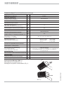
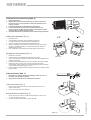
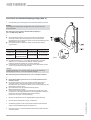
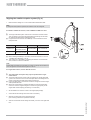
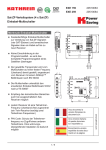
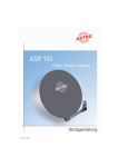
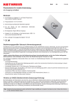
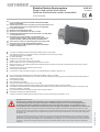
Einkabel-Quatro-Speisesystem
Single-cable quatro feed system
Système d’alimentation quatro monocâble
UAS 481
20110011
10,70-12,75 GHz
Q
Q
Q
Q
Q
Q
Q
Q
Q
Q
Q
Q
Q
Q
Q
Q
Q
Q
Q
Q
Q
Q
Q
Q
Q
Q
Q
Q
Q
Für den Empfang der Satelliten ASTRA, EUTELSAT/HOTBIRD,
Telecom und TürkSat
Einkabel-Speisesystem für 4 Anschlüsse mit zwei Polarisationen und
zwei Frequenzbereichen (Low-/High-Band bzw. analog/digital)
Für lineare Polarisation
Bestückt mit Einkabel-Quatro-LNB
Speist bis zu vier DVB-S-Receiver über ein Kabel
Unabhängige Wahlmöglichkeit horizontal/vertikal, Low-/High-Band
von jedem Receiver aus
Umschaltung horizontal/vertikal, Low-/High-Band und
Transponderwahl erfolgt im LNB, gesteuert vom Receiver mit
speziellem DiSEqC™-Befehlssatz gemäß prEN 50494:2006
Jeder Receiver erhält einen Übertragungskanal fest zugeordnet
Stromversorgung erfolgt über Niederführungskabel
Komplettschutz von LNB und Kabelanschlüssen im belüfteten
Gehäuse, Schutzart: IP 54
To receive the satellites ASTRA, EUTELSAT/HOTBIRD, Telecom and TürkSat
One cable feed system for 4 connections with two polarisations and two frequency ranges
(low band/high band or analog/digital)
For linear polarisation
Equipped with single-cable quatro LNB
Supplies up to four DVB-S receivers over one cable
Option to select horiz./vert., low band/high band from each receiver
Switching horiz./vert., low band/high band and transponder selection carried out in the LNB, controlled by the receiver with a specific
DiSEqCTM command set
One transmission channel is allocated to each receiver
Power supply via drop cable
Full protection of LNB and cable connections in a ventilated housing, protection category IP 54
Pour la réception des satellites ASTRA, EUTELSAT/HOTBIRD, Telecom et TürkSat
Système d’alimentation monocâble pour 4 connexions avec deux polarisations et deux gammes de fréquences (bande basse/haute ou
analogique/numérique)
Pour polarisation linéaire
Avec LNB Quatro monocâble
Alimente jusqu’à quatre récepteurs DVB-S via un câble
Possibilité de sélection indépendante horizontale/verticale, bande basse/haute depuis chaque récepteur
Commutation horizontale/verticale, bande basse/haute et sélection du transpondeur dans le LNB, commande par le récepteur à l’aide
d’instructions DiSEqC™ spéciales
Un canal de transmission est affecté de manière fixe à chaque récepteur
Alimentation électrique par câble descendant
Protection complète du LNB et des branchements dans un boîtier ventilé du type de protection : IP 54
Hinweise/Notes/Remarques
Das Speisesystem UAS 481 darf ausschließlich an die aufgeführten Kathrein-Parabolantennen montiert werden.
Für das Speisesystem gelten die gleichen Sicherheits- und Gefahrenhinweise, wie sie in den Anwendungshinweisen
der Offset-Parabolantennen aufgeführt sind. Bitte beachten Sie unbedingt diese Hinweise, da sonst Gefahren für Sie
oder Ihre Mitmenschen auftreten können (Stromschlag durch Freileitungen, Absturzgefahr, herabfallende Teile, Gewitter etc.)
The UAS 481 feed system may only be mounted to the listed Kathrein parabolic antennas. The feed system is subject to the same
safety and danger warnings as listed in the instructions for using offset parabolic antennas. Please follow these instructions at all times,
as otherwise you or other people may be exposed to danger (electric shock through overhead lines, risk of falling down, falling parts,
thunderstorm etc.)
Le système d’alimentation UAS 481 ne doit être monté que sur les antennes paraboliques Kathrein. En ce qui concerne le système
d’alimentation, les instructions de danger et de sécurité appliquées sont identiques à celles décrites dans les instructions d’utilisation
desantennes paraboliques Offset.Veuillez suivre scrupuleusement ces instructions, sinon vous risqueriez de vous mettre vous-même
en danger ou d‘autres personnes (décharge électrique due à des câbles aériens, risque de chute, pièces risquant de se détacher,
orage etc.)
936.2959/B/0906/1.10d/e/f
Q
Technische Daten/Technical data/Données techniques
Typ/Type/Type
UAS 481
Bestell-Nr./Order no./Référence
20110011
Geeignet für Parabolspiegel
Suitable for parabolic antennas
Convient pour antenne parabolique
CAS 60/75/90/120
Vertikal und horizontal/Vertical and horizontal/Verticale et horizontale
Polarisation
Eingangsfrequenz/
Input frequency/Fréquence d’entrée
Speisesystem-Rauschmaß/25 °C
Feed system noise figure/25 °C
Facteur de bruit du système d’alimentation/25 °C
LNB-Rauschmaß/25 °C
LNB noise figure/25 °C/Facteur de bruit du LNB/25 °C
Verstärkung/Gain/Gain
Teilnehmer-Frequenzen
Subscriber frequencies/Fréquences abonnés
Oszillatorfrequenz (L.O.)
Oscillator frequency (L.O.)/Fréquence d’oscillateur (L.O.)
Phasenrauschen (L.O.: 10,20 GHz)
Phase noise (L.O.: 10.20 GHz)
Bruit de phase (L.O.: 10,20 GHz)
Systemgüte (G/T)
System figure of merit (G/T)
Facteur de qualité du système (G/T)
Polarisationsentkopplung
Polarisation decoupling/Découplage de polarisation
Ausgang/Impedanz
Output/impedance / Sortie/impédance
GHz
10,70-12,75
dB
1,0
dB
0,9
dB
> 61
MHz
1400/1516/1632/1748
GHz
10,2
dBc
1 kHz: -60, 10 kHz: -80, 100 kHz: -85
mit/with/avec
dB/K
CAS 06, 60
CAS 075, 75, 75/R
CAS 09, 90, 90/R
CAS 120
14,1/15,0 dB/K
16,6/17,6 dB/K
18,1/19,1 dB/K
21,3/22,3 dB/K
dB
Typ. 25
Ω
1 x F-Connector/75
V
11,5-19 (Stromversorgung: 11,5-14; Steuerung: 16-19 u. DiSEqC™)
gemäß prEN 50494:2006
11.5-19 (power supply: 11.5-14; control: 16-19 & DiSEqCTM) acc. to prEN 50494:2006
11,5-19 (alimentation électrique: 11,5-14; commande: 16-19 et DiSEqC™)
selon prEN 50494:2006
Stromaufnahme LNB
Power consumption LNB/Consommation de courant LNB
mA
Typ. 230
Abmessungen/Dimensions/Dimensions
mm
250 x 44 x 148
Verpackungs-Maße/
Packing dimensions/Dimensions de l’emballage
mm
300 x 70 x 190
kg
1,6
Versorgungsspannung LNB (Eingang)
Supply voltage LNB (input)
Tension d’alimentation LNB (entrée)
Gewicht ca./Approx. weight/Poids env.
Abb. 1/Fig. 1
936.2959/B/0906/2.10def
Speisesystem-Montage (Abb. 1)
Mounting the feed system (Fig. 1)
Montage de la système d´alimentation (Fig. 1)
Polarisations-Voreinstellung (Abb. 2)
1
2
3
4
5
Haube abmontieren
Wert für die Polarisations-Voreinstellung von Seite 9 entnehmen.
Bei einem von den voreingestellten 0° abweichenden Wert ist wie
folgt zu verfahren:
Kombiteil-Dichtelement und Kabelhalter herausziehen
Innen-Sechskantschraube S lockern und durch Drehen des
Speisesystemes den Wert Ihres Standortes lt. beiliegender Tabelle
einstellen. Max. Anziehdrehmoment: 6 Nm
Kombiteil-Dichtelement und Kabelhalter bis auf Anschlag eindrücken
Setting the polarisation (Fig. 2)
1
2
3
4
5
Dismantle cover
The polarisation presetting value is available on page XX.
Proceed as follows if a value deviates from the default 0°:
Remove combination part sealing element and cable clip
Slacken off hexagon socket screw S and set the value for your location
as given in the attached table by turning the feed system. Maximum
tightening torque: 6 Nm
Push combination part sealing element and cable clip all the way in
Ajustage de la polarisation (Fig. 2)
1
2
3
4
5
Démonter le capuchon
Relever la valeur de préréglage de polarisation à la page 9.
Avec une divergence de valeur par rapport à la valeur de préréglage de 0°,
procéder comme suit :
Retirer l’élément d’étanchéité de la pièce combinée et la fixation du câble
Desserrer la vis à six pans creux S et tout en pivotant le système
d’alimentation, régler la valeur de votre site géographique selon le tableau
ci-joint. Couple de serrage maximum : 6 Nm
Enfoncer l’élément d’étanchéité de la pièce combinée et la fixation du câble
jusqu’en butée
Abb. 2/Fig. 2
Kabelanschluss (Abb. 3)
1
2
Beiliegenden F-Stecker auf Kathrein-Kabeltyp LCD 95, 99 oder 111
montieren und am LNB anschließen
Angeschlossenes Kabel in den Kabelhalter eindrücken
Cable connection (Fig. 3)
1
2
Mount F-plug included onto Kathrein cable model LCD 95, 99 or 111
and connect to LNB
Press connected cables into cable clip
Raccordement de câbles (Fig. 3)
2
Monter la fiche F ci-jointe sur le type de câble Kathrein LCD 95, 99 ou
111 et la raccorder sur le LNB
Enfoncer le câble raccordé dans la fixation du câble
Abb. 3/Fig. 3
936.2959/B/0906/3.10def
1
Ausrichten der Satelliten-Empfangsanlage (Abb. 4)
1
Grundeinstellung nach beiliegender Azimut-/Elevationstabelle vornehmen
Hinweis:
Wird lediglich das Speisesystem ausgetauscht, kann das Ausrichten der
Antenne entfallen.
Bei Verwendung eines Kathrein-Satelliten-Messempfängers,
wie z. B. MSK 25 oder MSK 33:
2
Q
Q
Das Einkabel-Speisesystem muss zuerst mit dem Messempfänger
verbunden werden. Diese Verbindung darf bis zum Abschluss der
Einstellarbeiten nicht unterbrochen werden, da sonst die Einstellungen des
Speisesystems verloren gehen
Den Messempfänger mit DiSEqC™-Befehl aus der Beispiel-Tabelle
programmieren:
Satellit
Transponder
Programm
DiSEqC™-Befehl
ASTRA 19,2°
11,836 GHz, H-Pol.,
SR 27.500, CR 3/4
Das Erste (ARD)
E0 10 5A 0D 99
HOTBIRD 13°
11,604 GHz, H-Pol.,
SR 27.500, CR 5/6
Das Erste (ARD)
E0 10 5A 09 5F
Abb. 4
Q
Q
Den Messempfänger auf 14 V und die Eingangsfrequenz 1400 MHz
einstellen (L.O.=0) und danach den DiSEqCTM-Befehl absenden.
Im Beispiel werden die Signale auf 1400 MHz übertragen.
Anschließend durch Drehen über die Azimut-Achse gewünschten Sender
suchen und auf Maximal-Anzeige einstellen.
Hinweis:
Einkabel-Steckdosen, wie z. B. ESU 33 oder 34 trennen die Verbindung,
sobald länger als 400 ms 18 V an der Steckdose anliegen!
Bei Verwendung eines Einkabel-Receivers, wie z. B. Kathrein UFS 821:
2
Q
Q
Q
Das Einkabel-Speisesystem kann nur mit einem Einkabel-Receiver
betrieben werden
Der Einkabel-Receiver muss zuerst mit dem Einkabel-Speisesystem
verbunden werden. Diese Verbindung darf bis zum Abschluss der
Einstellarbeiten nicht unterbrochen werden, da sonst die Einstellungen des
Speisesystems verloren gehen
Den Einkabel-Receiver auf Einkabel-Betriebsart gemäß
Bedienungsanleitung umstellen
Durch Drehen über die Azimut-Achse gewünschten Sender suchen und
auf Maximum an der Signalstärke bzw. an der Signalqualitäts-Anzeige am
Einkabel-Receiver gemäß Bedienungsanleitung einstellen
(siehe hierzu auch Abb. 5 mit Beschreibung)
3
Elevation auf Maximalwert an der Signalqualitäts-Anzeige einstellen
4
Azimut-Einstellung überprüfen und ggf. nachjustieren
5
Alle Befestigungsteile auf das vorgeschriebene Drehmoment festziehen
(siehe auch Montageanleitung der Parabolantenne)
6
Nach den Anschluss- und Einstellarbeiten Abdeckhaube wieder aufsetzen
und festschrauben
936.2959/B/0906/4.10def
Q
Aligning the satellite reception system (Fig. 4)
1
Make the basic settings acc. to the enclosed azimuth/elevation table
Note:
If merely the feed system is replaced, the antenna must not be aligned.
If a Kathrein satellite test receiver, such as MSK 25 or MSK 33 is used:
2
Q
Q
The single-cable feed system must first be connected to the test receiver.
This connection must not be interrupted before the settings are all made,
as otherwise the feed system settings will be lost.
Programme the test receiver with a DiSEqCTM command taken from the
examples-table:
Satellite
Transponder
Channel
DiSEqC™command
11,836 GHz, H-Pol.,
ASTRA 19,2°
Das Erste (ARD)
SR 27.500, CR 3/4
E0 10 5A 0D 99
11,604 GHz, H-Pol.,
Das Erste (ARD)
SR 27.500, CR 5/6
E0 10 5A 09 5F
HOTBIRD 13°
Q
Q
Before sending the DiSEqCTM command, set the test receiver to 14V and
1,400 MHz input frequency (L.O.=0).
Then search for a transmitter by swivelling the reflector over the azimuth
axis, and set it to maximum indication
Abb. 4
Note:
Single-cable wall outlets, such as ESU 33 or ESU 34 interrupt the connection if
18 V are applied to the wall outlet longer than 400 ms!
If a single-cable receiver, such as UFS 821 is used:
2
Q
Q
Q
The single-cable feed system may only be operated with a singlecable receiver
The single-cable receiver must first be connected to the single-cable feed
system. This connection must not be interrupted before the settings are all
made, as otherwise the feed system settings will be lost
Follow the description in the receiver manual to change the mode to singlecable operational mode
Search for a transmitter by swivelling the antenna over the azimuth axis,
and set to maximum signal strength or to maximum signal quality on the
single-cable receiver display (see also fig. 5 and the text)
3
Set the elevation to maximum value on the signal quality display
4
Check the azimuth settings and correct them if necessary
5
Seize all mounting parts to the prescribed torque
(see mounting instructions of parabolic antenna)
6
After the connections and all settings are made, put on the cover again and
fix it
936.2959/B/0906/5.10def
Q
Orientation de l‘installation de réception satellite (Fig. 4)
1
Effectuer le réglage de base d‘après le tableau d‘azimut/élévation joint.
Remarque :
Si seul le système d‘alimentation est remplacé, l‘orientation de l‘antenne est
inutile !
En cas d‘utilisation d‘un récepteur de mesure satellite Kathrein comme
par ex. MSK 25 ou MSK 33:
2
Q
Q
Le système d‘alimentation monocâble doit être relié en premier au
récepteur de mesure. Cette liaison ne doit pas être interrompue avant la fin
des réglages faute de quoi le réglage du système d‘alimentation est perdu.
Programmer le récepteur de mesure avec la commande DiSEqC donnée
dans le tableau d’exemples :
Satellite
Transpondeur
Programme
Instruction
DiSEqC™
ASTRA 19,2°
11,836 GHz, H-Pol.,
Das Erste (ARD)
SR 27.500, CR 3/4
E0 10 5A 0D 99
HOTBIRD 13°
11,604 GHz, H-Pol.,
Das Erste (ARD)
SR 27.500, CR 5/6
E0 10 5A 09 5F
Abb. 4
Q
Q
Avant de transmettre l’instruction DiSEqC, régler le récepteur de mesure
sur 14 V et une fréquence d’entrée sur 1400 MHz (L.O.=0).
Rechercher ensuite l‘émetteur par rotation autour de l‘axe d‘azimut et
régler sur l‘affichage maximal.
Remarque :
Les prises monocâbles comme par ex. ESU 33 ou ESU 34 coupent la liaison si
la prise reçoit 18 V pendant plus de 400 ms !
En cas d‘utilisation d‘un récepteur monocâble comme par ex. UFS 821 :
2
Q
Q
Q
Le système d‘alimentation monocâble ne peut fonctionner qu‘avec un
récepteur monocâble !
Le récepteur monocâble doit être relié en premier au système
d‘alimentation monocâble. Cette liaison ne doit pas être interrompue avant
la fin des réglages faute de quoi le réglage du système d‘alimentation est
perdu.
Régler le récepteur monocâble sur le mode de fonctionnement monocâble
conformément au manuel d‘utilisation.
Rechercher l‘émetteur par rotation autour de l‘axe d‘azimut et régler sur
le maximum sur l‘afficheur d‘intensité du signal ou de qualité du signal du
récepteur monocâble conformément au manuel. Voir également la fig. 5 et
le texte.
3
Régler l’élévation sur la valeur maximale sur l’afficheur de qualité du signal.
4
Vérifier le réglage d‘azimut et le ré-ajuster si nécessaire.
5
Serrer tous les éléments de fixation au couple prescrit (voir la notice de
montage de l‘antenne parabolique).
6
A l‘issue des branchements et réglages, remettre en place et visser le
capot.
936.2959/B/0906/6.10def
Q
Da die Antennenkeule im Bereich des Maximums nur leicht gekrümmt ist,
ist bei Ausrichtung in diesem Bereich eine gute Bildqualität zu erwarten.
Jedoch kann es aber sein, dass die Antenne links oder rechts „gerade
noch“ auf diesen guten Empfangsbereich ausgerichtet ist.
Schon bei den ersten Schwankungen des Antennen-Standrohres kann die
vermeintlich gute Bildqualität über die steilen Keulenflanken abstürzen.
Um dies zu vermeiden, sollte die Empfangsanlage auf Mitte des Pegelmaximums eingestellt werden.
Zur Einstellung mit Hilfe eines Kathrein-Satelliten-Messempfängers,
wie z. B. MSK 25 oder MSK 33, gehen Sie wie folgt vor:
1 Mitte der Mastschelle markieren
2 Antenne nach links drehen, bis ein Pegelabfall von z. B. 8 dB
(oder Spikes) auftritt
3 Antenne nach rechts drehen, bis ein Pegelabfall von 8 dB auftritt.
Anschließend Mastschellen-Markierung auf den Mast übertragen.
4 Dann Mastschellen-Markierung genau in die Mitte der
Mastmarkierungen stellen. So wird die bestmögliche
Empfangssituation erreicht
Für die Elevations-Optimierung ist ebenso zu verfahren.
As the antenna lobe in the maximum range is only slightly curved, an excellent
picture quality can be expected when it is aligned to this range.
However, it may also be that the antenna at the left or right is “only just” aligned
to this excellent reception range.
As soon as the antenna stanchion experiences any vibration the supposed
excellent picture quality can drop off at the steep edge of the lobe.
To avoid this, the reception position should be set to the middle of the maximum
level.
Proceed as follows when conducting the setting-up process using a Kathrein
test receiver such as MSK 25 or MSK 33:
1 Mark the centre of the mast clamp
2 Turn the antenna to the left until the level drops by, e.g. 8 dB
(or spikes occur)
3 Turn antenna to the right until the level drops by 8 dB.
Then transfer the mast clamp marking to the mast.
4 Position the mast clamp marking in the exact centre of the mast markings.
This will ensure that an ideal reception situation is given
Proceed in a similar manner to optimise the elevation.
Abb./Fig.5
Pour éviter ceci, l’installation de réception doit être réglée sur le milieu du
maximum du niveau.
Pour le réglage à l’aide d’un récepteur de mesure satellite Kathrein,
tel que MSK 25 ou MSK 33, procéder comme suit :
1 Marquer le milieu de la cheville du mât
2 Pivoter l’antenne vers la gauche, jusqu’à ce qu’une chute de niveau par ex.
de 8 dB (ou spikes) intervienne
3 Pivoter l’antenne vers la droite, jusqu’à ce qu’une chute du niveau de 8 dB
intervienne.
Ensuite reporter la marque de la cheville du mât sur le mât.
4 Puis placer la marque de collier du mât exactement au milieu des marques
du mât. De cette façon la meilleure position possible de réception est
obtenue
Pour optimiser l’élévation, procéder de la même façon.
936.2959/B/0906/7.10def
Etant donné que le lobe de rayonnement de l’antenne n’est que légèrement
incliné au niveau du maximum, la qualité de l’image devrait être satisfaisante.
Il se peut pourtant que l’antenne à gauche ou à droite se trouve « tout juste
encore » orientée sur cette réception.
Dès les premières oscillations du tube de positionnement de l’antenne,
ladite bonne qualité de l’image peut chuter sur les flancs abrupts du lobe de
rayonnement.
Anwendungsbeispiele (Abb. 6-8)
Application examples (Fig. 6-8)
Exemples d´application (Fig. 6-8)
*
*
*
936.2959/B/0906/8.10def
Achtung:
Abschluss mit kapazitiver Trennung verwenden (z. B. ERA 14)
Attention:
Use terminator with capacitive separation (such as ERA 14)
Attention:
Utiliser une résistance terminale avec une séparation capacitive (par ex. ERA 14)
-2
-11
4
-4
-7
-16
6
2
-13
-10
-17
-23
-27
-17
-19
-23
-32
-7
-21
-26
-29
-30
Albanien/Albania/L´Albanie
Belgien/Belgium/La Belgique
Bulgarien/Bulgaria/Bulgarie
Dänemark/Denmark/Danemark
Deutschland/Germany/Allemagne
Frankreich/France/France
Finnland/Finland/Finlande
Griechenland/Greece/Grèce
Großbritannien/Great Britain/La Grande-Bretagne
Italien/Italy/L´Italie
Irland/Ireland/L´Irlande
-1
7
4
-17
3
7
9
-3
6
13
-22
7
2
6
-4
-5
-4
-2
4
-12
-1
-8
14
10
-9
0
2
14
-5
8
ASTRA
19.2°
Ost
East/Est
3
0
-21
-1
3
5
-7
1
9
-26
2
-2
1
-8
-9
-8
-6
1
-17
-4
-13
11
5
-13
-4
-3
10
-9
5
EUTELSAT
W2
16°
Ost
East/Est
6
2
-18
2
6
8
-5
2
11
-23
5
0
2
-6
-6
-6
-3
4
-15
-1
-11
14
6
-10
-2
-1
13
-7
8
HOTBIRD
13°
Ost
East/Est
9
5
-15
5
8
11
-2
4
14
-20
7
3
4
-4
-3
-3
0
7
-13
3
-9
18
7
-7
0
1
16
-5
11
EUTELSAT
W1
10°
Ost
East/Est
11
7
-11
8
11
14
1
5
17
-17
9
6
5
-1
0
-1
2
10
-11
6
-7
21
9
-5
3
3
19
-2
15
EUTELSAT
W3A
7°
Ost
East/Est
18
13
-2
15
17
21
8
9
23
-8
15
13
9
5
9
6
10
17
-6
15
-2
28
12
3
9
8
25
4
22
Thor 2/3
0.8°
West
West/Ouest
21
16
3
18
20
24
12
11
26
-3
18
16
10
8
13
9
13
20
-3
19
1
32
14
7
12
11
29
8
26
Atlantic
Bird 3
5°
West
West/Ouest
´23/11
´19/7
´6/5
´21/9
´22/10
26/14
´15/§
´13/1
28/16
0/-12
´20/8
´18/6
12/0
10/-2
´16/4
12/0
`16/4
´23/11
0/12
´22/10
3/-9
34/22
15´/3
10/-2
14´/2
´13/1
31/19
10/-2
28/16
Atlantic
Bird 2/
Telecom 2D
8°
West
West/Ouest
35
31
29
34
34
39
30
21
38
24
31
32
19
24
32
26
31
36
15
37
17
46
21
27
28
24
41
25
41
Hispasat
1C/1D
30°
West
West/Ouest
936.2959/B/0906/9.10def
Trouvez d´autres pays ou villes sur notre page dans l´internet: www.kathrein.de/de/sat/index.htm dans le point de menu “satellite receiving systems/technical information/azimut/elevation and polarisation-presetting“.
Find more countries or cities on the Kathrein-website on the Internet: www.kathrein.de/de/sat/index.htm, under: “satellite receiving systems/technical information/azimut/elevation and polarisation-presetting“.
Weitere Länder bzw. Städte in diesen Ländern finden Sie im Internet auf der Kathrein-Homepage unter „www.kathrein.de/de/sat/index.htm“ im Menüpunkt
„Satelliten-Empfangsanlagen/Technische Infos/Azimut/Elevation und Polarisations-Voreinstellung“.
-20
-24
Ungarn/Hungary/La Hongrie
-5
-24
Slowenien/Slovenia/Slovénie
-4
0
-18
Slowakei/Slovakia/Slovaquie
-40
-1
-21
Serbien-Montenegro/Serbia and Montenegro/Serbie-Monténégro
-21
-11
-28
Schweiz/Switzerland/Suisse
Tschechien/Czech Republic/Republique Tchéque
1
-12
Schweden/Sweden/Suède
Spanien/Spain/L´Espagne
4
-16
Rumänien/Romania/Roumanie
Österreich/Austria/L´Autriche
0
-24
Norwegen/Norway/Norvège
-28
-6
-11
Niederlande/Netherlands/Les Pays-Bas
-17
2
-25
Monaco/Monaco/Monaco
-43
-10
-31
Luxemburg/Luxemburg/Luxembourg
Polen/Poland/Pologne
-11
-13
-26
Liechtenstein/Liechtenstein/Liechtenstein
Portugal/Portugal/Portugal
-5
-10
-24
-26
Kroatien/Croatia/Croatie
Land/Country/Pays
ASTRA
(Eurobird 1)
28.2°
Ost
East/Est
TÜRKSAT
42° Ost
East/Est
Satelliten/Satellites/Stellites
Préréglage de polarisation pour des têtes compactes dans des pays européens differents (le milieu géographique de chaque pays est le point de référence respectif)
Si le préréglage de polarisation est plus de ± 25°, la tête doit être réglée à la butée respective
Polarisation-presettings for compact feed systems in various European countries (the geographical centre of each country is the point of reference in each case)
In case of polarisation-presettings exceeding ± 25°, the feed system is to be set to the respective stop.
Polarisations-Voreinstellungen für Compact-Speisesysteme in verschiedenen europäischen Ländern (Bezugspunkt ist jeweils die geografische Mitte des Landes).
Bei Polarisations-Voreinstellungen größer als ± 25° ist das Speisesystem auf den jeweiligen Anschlag einzustellen.
Polarisations-Voreinstellungen in verschiedenen Ländern für Compact-Speisesysteme
Pre-setting the polarisation for Compact feed systems in various countries
Présélection de la polarisation des têtes compactes SHF pour différents pays
Elektronische Geräte gehören nicht in den Hausmüll, sondern müssen gemäß Richtlinie 2002/96/EG DES EUROPÄISCHEN PARLAMENTS UND
DES RATES vom 27. Januar 2003 über Elektro- und Elektronik-Altgeräte
fachgerecht entsorgt werden.
Bitte geben Sie dieses Gerät am Ende seiner Verwendung zur Entsorgung
an den dafür vorgesehenen öffentlichen Sammelstellen ab.
Internet: http://www.kathrein.de
KATHREIN-Werke KG . Anton-Kathrein-Straße 1 – 3 . Postfach 10 04 44 . D-83004 Rosenheim . Deutschland . Telefon (0 80 31) 1 84-0 . Fax (0 80 31) 1 84-3 06
936.2959/B/0906/10.10def
Les appareils électroniques ne doivent pas être mis dans la poubelle
de la maison, mais doivent être recyclés correctement selon la directive
2002/96/EG DU PARLEMENT ET DU CONSEIL EUROPEEN du
27 janvier 2003 concernant les appareils électroniques et électriques
usagés.
Nous vous prions de mettre cet appareil à la fi n de son utilisation dans
un emplacement prévu pour son recyclage.
Technische Änderungen vorbehalten/Subject to technical changes/Nous nous réservons le droit de toutes modifications techniques
Electronic equipment is not household waste - in accordance with
directive 2002/96/EC OF THE EUROPEAN PARLIAMENT AND THE
COUNCIL of 27th January 2003 on used electrical and electronic
equipment, it must be disposed of properly.
At the end of its service life, take this unit for disposal at a relevant
offi cial collection point.