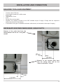
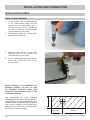
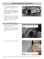
1
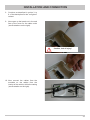
Installation Manual
Caravan roof gland
HDZ 100
Protective casing for cable interfaces
on the caravan roof for Kathrein
rotary antenna systems type CAP series
CONTENTS
CONTENTS ............................................................................................................................... 2
FOREIGN LANGUAGE INSTALLATION MANUALS/SERVICE ...................................................... 3
ADDRESS OF THE SERVICE CENTRE ..................................................................................... 3
HDZ 100 COMPONENTS/SCOPE OF SUPPLY ............................................................................ 4
HDZ 100 SCOPE OF SUPPLY .................................................................................................. 4
PROPER USE ........................................................................................................................... 5
PROPER USE (USE FOR THE INTENDED PURPOSE) .............................................................. 5
SAFETY INSTRUCTIONS - IMPORTANT NOTES ......................................................................... 6
INSTALLATION EXAMPLES....................................................................................................... 8
BASIC VARIANTS .................................................................................................................... 8
INSTALLATION AND CONNECTION ........................................................................................... 9
REQUIRED TOOLS AND EQUIPMENT ...................................................................................... 9
NECESSARY SPACINGS WHEN USING CABLE DUCTS ............................................................ 9
INSTALLATION STEPS .......................................................................................................... 10
ROOF GLAND VARIANT ........................................................................................................
CABLE CONTINUATION VARIANT ...........................................................................................
10
12
TECHNICAL DATA (in mm) ...................................................................................................... 15
FOR YOUR NOTES ................................................................................................................. 16
2
FOREIGN LANGUAGE INSTALLATION MANUALS/SERVICE
Dear Customer, Chère Cliente, Cher Client, Gentile cliente, Estimado cliente,
GB
You can obtain an English version of our installation instructions from our representatives in your country
(http://www.kathrein.de/include/kontakte_groups_eng.cfm?kontinent=1&gruppe=SAT) or download one
from our homepage (http://www.kathrein.de/en/sat/index.htm).
ADDRESS OF THE SERVICE CENTRE
ESC
Electronic Service Chiemgau GmbH
Bahnhofstraße 108
83224 Grassau
Telefon:
Telefax:
Internet:
E-Mail:
(0 86 41) 95 45-0
(0 86 41) 95 45-35 und -36
http://www.esc-kathrein.de
[email protected]
3
HDZ 100 COMPONENTS/SCOPE OF SUPPLY
• Protective casing for cable interfaces on the
caravan roof for Kathrein rotary antenna systems
type CAP series
• Capable of accepting up to two RF cables
(Ø 5 mm) and one DC cable (Ø 6.5-7 mm)
• The cables can optionally be fed downwards from
the HDZ 100 casing into the vehicle interior or out
from the casing to other points on the vehicle roof
• Functionally appropriate sealing of the roof opening
after disconnecting the cable connections when
removing the CAP turntable
• Easy access to the cable interfaces combined with
correct arrangement on the vehicle roof
HDZ 100 SCOPE OF SUPPLY
•
•
•
•
4
Cover with two gaskets and four
captive screws
Sealing plug
Bottom half of the casing with gasket
and six plugs
Three fastening screws
PROPER USE
PROPER USE (USE FOR THE INTENDED PURPOSE)
The HDZ 100 roof gland protects the cable connection point and the roof gland point when laying cables
from CAP systems on the caravan or mobile home roof.
The gland seatings are designed for two cables (Ø 5 mm) and one cable (Ø 6.5-7 mm).
Any use other than that specified above will void the warranty or guarantee.
The following circumstances result in the loss of all warranty and liability claims towards
the manufacturer:
•
•
•
•
Improper installation
Missing or insufficient sealant under the protective casing
Use of cables with diameters other than 2 x 5 mm and 1 x 6.5-7 mm
Failure to observe installation and safety instructions in this manual
The system may only be installed by qualified specialist
personnel!
To prevent hazards during installation, operation or when driving on public highways, the
instructions and information in this manual must be strictly adhered to.
5
SAFETY INSTRUCTIONS - IMPORTANT NOTES
Safety during installation work
When carrying out installation work in locations where there is a risk of falling, take appropriate
safety precautions, e.g. use of a working platform. Make sure that the vehicle roof is
sufficiently strong and stable to carry out the installation work (risk of damage or collapsing
of roof).
In case of doubt, contact a qualified specialist dealer or the manufacturer of your vehicle
to find an appropriate installation location.
Make sure that:
-
The turntable and connected units are disconnected from the power supply
-
The person carrying out the installation or repair does not suffer from vertigo and can move around
safely on the roof of the caravan or motor home
-
The person carrying out the installation or repair is wearing sturdy and non-slip shoes
-
The person carrying out the installation or repair has a secure position to stand and hold on while
working
-
The roof and the climbing equipment used (e.g. ladder) are dry, clean and non-slip
-
The roof can withstand the weight of the person carrying out the repairs
-
Nobody should be inside the caravan/motor home underneath the installation position during
dismantling/installation
Attention! Risk of death or injury due to falling or the roof collapsing!
Attention! Risk of death or injury due to possible roof collapsing and falling parts!
Proper installation and safety
Essential information
The HDZ 100 should be fitted only in a horizontal position. The correct execution of the installation and the
electrical connections are important for safety.
Adhesive sealant
The HDZ 100 is attached to the roof of the vehicle by adhesive and is secured by additional screws.
Note that the curing of the adhesive sealant is temperature-dependent. It reaches its full strength only
after approximately five days.
During installation work, comply strictly with the processing and safety instructions
for the adhesive sealant (Sikaflex® 291 safety data sheet and Sikaflex® 291 technical
data sheet).
Plugs
Unused cable channels in the protective casing should in all cases be closed off using the attached
plugs, since otherwise water will penetrate through these free openings.
Cables
Lay all cables such that nobody can tread on them or trip over them.
When connecting the power cables (receiver and turntable) to the vehicle electrical supply, make sure
that the cable polarity is not reversed.
6
SAFETY INSTRUCTIONS - IMPORTANT NOTES
If the cable polarity is reversed there is a risk of thermal overload and damage
to components when the equipment is powered up!
If cable ducts are used to protect the cables, up to a size of 31 x 17 mm they can be concealed in the
recess in the casing hood.
The height of 17 mm should not be exceeded for turntables carrying a planar
antenna (CAP 610/HDP 600), since at the steepest elevation of 10° the planar antenna
can foul the cable duct during rotation.
If the CAP 710‘s cable trunking is laid as a direct continuation of the cable exit,
the height of the cable trunking must not exceed 20 mm, otherwise the turntable will
collide with the cable trunking during operation. The cable trunking may exceed 20 mm
in height 50 mm after the cable exit.
If the cable duct is laid as a direct continuation of the CAP 910 cable outlet, the
height of the cable duct must be less than 10 mm, otherwise when the hood of the
CAP 910 infeed system is in the park position it will foul the duct.
7
INSTALLATION EXAMPLES
BASIC VARIANTS
Roof gland with cable interface
Roof gland without cable interface
Cable continuation with cable interface
CAP 610
and
CAP 710
Note:
CAP 610
and
CAP 710
CAP 610
and
CAP 710
CAP 910
CAP 910
8
For the CAP 610/710 units there are always
two cables emerging from the turntable.
For the CAP 910 unit there are always three
cables emerging from the turntable.
INSTALLATION AND CONNECTION
REQUIRED TOOLS AND EQUIPMENT
•
•
•
•
•
•
•
•
Circular cutter, Ø 38 mm
Cross-head screwdriver for M4 screws
Power drill
Twist drill Ø 2.5 mm
Knife
Round file or emery paper
Sikaflex® 291 sealant (included in the CAP turntable scope of supply. Comply with the respective
safety instructions for the sealant)
If required for the type of installation selected: cable ducts (not included in the scope of supply)
NECESSARY SPACINGS WHEN USING CABLE DUCTS
Distance of the cable duct from the
casing bottom half for the “roof gland”
variant
20
Distance of the second cable duct
from the casing lower half for the
“cable continuation” variant
20
9
INSTALLATION AND CONNECTION
INSTALLATION STEPS
ROOF GLAND VARIANT
1.
In the centre of the intended position
of the cable outlet spigot, drill the
opening for the cable gland with a
circular cutter (Ø 38 mm). Deburr the
hole with a round file or emery paper
(see illustration on the right).
2.
Provisionally insert the casing lower
half into the drilled hole.
3.
Mark out the positions of the three
fastening holes on the vehicle roof
(see illustration on the right).
4.
At the marked positions, drill the three
holes with a twist drill (Ø 2.5 mm,
20 mm deep).
The prerequisite for good adhesive
characteristics is a clean, dry and greasefree substrate. You should therefore use a
suitable cleaning agent to clean the area of
roof surface covered by the casing lower
half around the drilled hole, and then allow
the surface to dry thoroughly.
10
70 mm
Before starting to use Sikaflex® 291
adhesive sealant, be sure to read
the Sikaflex® Products safety data
sheet and technical data sheet in this
installation manual!
50 mm
80 mm
INSTALLATION AND CONNECTION
If the surface is painted, ensure that the paint finish is sufficiently well bonded to the substrate.
If the coat of paint is already loose or peeling, it must be removed down to a stable layer in the area
to which the adhesive will bond. If you have any doubts concerning the adhesive characteristics,
consult a paint and lacquer specialist, or the manufacturer of your vehicle.
Under certain circumstances, it may be necessary for you to improve the adhesive properties of the roof
surface by pre-treatment with a cleaning agent available from specialist dealers (e.g. Sika® Cleaner) or a
primer (e.g. Sika® Primer).
5.
Ensure before starting adhesive work
that the temperature of materials to
be glued and the adhesive sealant is
between +5 °C and +40 °C. Prepare
all necessary fastening elements and
tools.
6.
Prepare the tube of adhesive sealant
in accordance with the instructions
enclosed with the tube.
7.
Apply the sealant all round and
evenly in the channel provided on the
underside of the casing (see illustration
on the right).
Avoid skin contact
circumstances!
under
all
Note also that the sealing contour
must be continuous and complete!
8.
Now screw the casing lower half into
place, using the three self-tapping
screws provided.
9.
Allow the cable ends to project
approx. 180 mm from the interior of
the vehicle and secure them with
plugs (see illustration on the right).
10. Now connect the cables and clip
them on the cable attachment
points provided (see illustration on
the right).
11
INSTALLATION AND CONNECTION
11. Use the plugs supplied to seal the
cable attachment points that are now
not required (see illustration on the
right).
Do not cut away any plugs that are
not required, you will need them
if you ever wish to remove the
turntable system.
12. Now place the cover on the casing
lower half and screw the two halves
together using the four screws preinserted in the cover (tightening
torque: MA = 1-1.5 Nm).
CABLE CONTINUATION VARIANT
1.
First cut the cylindrical spigot off the
underside of the casing. There are
two ways of doing this:
-
use a sharp knife to cut through the
wall between the base of the casing
and the spigot (see illustration on the
right) or
-
use a hammer to knock out the spigot
Caution, risk of injury!
Caution, risk of injury!
12
INSTALLATION AND CONNECTION
2.
Continue as described in points 3. to
8. of the description for the “roof gland”
variant.
9.
Now open up the break-out in the end
face of the cover for the cable outlet
(see illustrations on the right).
Caution, risk of injury!
10. Now connect the cables from the
turntable on the cables from the
interior of the vehicle, within the casing
(see illustration on the right).
13
INSTALLATION AND CONNECTION
11. Insert the cable in the seal and push
it into the cable clips in the casing
(see illustration on the right).
12. Use the plugs attached to seal the
cable attachment points that are now
not required (see illustration on the
right).
Do not cut away any plugs that are
not required, you will need them
if you ever wish to remove the
turntable system.
13. Now place the cover on the casing
lower half and screw the two halves
together using the four screws preinserted in the cover (tightening
torque: MA = 1-1.5 Nm).
14
TECHNICAL DATA (in mm)
max. 17
90
max. 31
Optional
optionaler
cable
outlet
Kabelausgang
up
3 cables
bis zuto3 Kabel
Cable
inlet
Kabeleingang
up
3 cables
bis zuto3 Kabel
28,5
20
( 65 )
37
211
2,5 (3x)
38
RAL
(grey white)
RAL9002
9002 (Grauweiß)
Interfaces:
Schnittstellen:
-- Roof
hole:
Ø 38 38
Dachbohrung:
-- Cable
duct: W=31,
Leitungsführungskanal:
B =31, HH=17
=17 max
max
- Cables: 2x RF
Ø 5; 1xDC
- Kabel: 2x HF
5; 1x DC
6,5 - 7
- Core-drilled hole in the substrate: 3x
- Kernbohrung in Unterkonstruktion: 3x
max
Ø 6.5 - 7 max
Ø 2.5 for self-tapping screws ST 3.5x19
2,5 für Blechschrauben ST3,5x19
Protection class according to EN 60529: IP55
Schutzart nach EN 60529: IP55
Packaging:
Verpackung:
- Single pack dimensions: L=225; W=165; H=67
Einzelverpackung:
L= 225;
B= 165; H= 67 L=358; W=233; H=181 (contains 5 items)
-- Outer
package
dimensions:
- Umverpackung: L= 358; B= 233; H= 181 (enthält 5Stk.)
Gross
weight:
Bruttogewicht:
0,35 kg0.35 kg
Net
weight:
0.25
Nettogewicht: 0,25
kg kg
]
(single
pack dimensions)
(Einzelverpackung)
15
936.3442/A/0310/ZWT - Technical data subject to change.
FOR YOUR NOTES
Internet: http://www.kathrein.de
KATHREIN-Werke KG • Anton-Kathrein-Straße 1 - 3
P.O. Box 100 444 • 83004 Rosenheim GERMANY