1
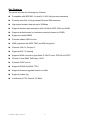
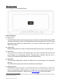
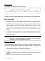
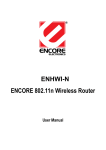
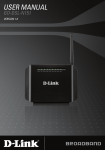
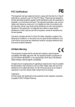
802.11n Wireless Series
Wireless Broadband Router
User Manual
Version: 2.0
Date: November 10, 2008
FCC Certifications
Federal Communication Commission Interference Statement
This equipment has been tested and found to comply with the limits for a Class B digital device,
pursuant to Part 15 of the FCC Rules. These limits are designed to provide reasonable protection
against harmful interference in a residential installation. This equipment generates, uses and can
radiate radio frequency energy and, if not installed and used in accordance with the instructions,
may cause harmful interference to radio communications. However, there is no guarantee that
interference will not occur in a particular installation. If this equipment does cause harmful
interference to radio or television reception, which can be determined by turning the equipment off
and on, the user is encouraged to try to correct the interference by one of the following measures:
-Reorient or relocate the receiving antenna.
-Increase the separation between the equipment and receiver.
-Connect the equipment into an outlet on a circuit different from that
to which the receiver is connected.
-Consult the dealer or an experienced radio/TV technician for help.
This device complies with Part 15 of the FCC Rules. Operation is subject to the following two
conditions: (1) This device may not cause harmful interference, and (2) this device must accept any
interference received, including interference that may cause undesired operation.
FCC Caution: Any changes or modifications not expressly approved by the party responsible for
compliance could void the user's authority to operate this equipment.
IMPORTANT NOTE:
FCC Radiation Exposure Statement:
This equipment complies with FCC radiation exposure limits set forth for an uncontrolled
environment. This equipment should be installed and operated with minimum distance 20cm
between the radiator & your body.
This transmitter must not be co-located or operating in conjunction with any other antenna or
transmitter.
November 10, 2008 / Version: 2.0
ii
CE Mark Warning
This equipment complies with the requirements relating to electromagnetic compatibility, EN
55022 class B for ITE, the essential protection requirement of Council Directive 89/336/EEC on
the approximation of the laws of the Member States relating to electromagnetic compatibility.
Company has an on-going policy of upgrading its products and it may be possible that information
in this document is not up-to-date. Please check with your local distributors for the latest
information. No part of this document can be copied or reproduced in any form without written
consent from the company.
Trademarks:
All trade names and trademarks are the properties of their respective companies.
Copyright © 2008, All Rights Reserved.
經型式認證合格之低功率射頻電機,非經許可,公司、商號或使用者均不得擅自變更頻率、
加大功率或變更原設計之特性及功能。
低功率射頻電機之使用不得影響飛航安全及干擾合法通信;經發現有干擾現象時,應立即停
用,並改善至無干擾時方得繼續使用。前項合法通信,指依電信法規定作業之無線電通信。
低功率射頻電機須忍受合法通信或工業、科學及醫療用電波輻射性電機設備之干擾。
November 10, 2008 / Version: 2.0
iii
Table of Contents
UNPACKING INFORMATION ···························································································· 1
INTRODUCTION TO WIRELESS ROUTER······································································· 1
General Description ····································································································· 1
Key Features ··············································································································· 3
The Front Panel ··········································································································· 4
The Rear Panel ··········································································································· 5
Placement (Optional) ··································································································· 5
INSTALLING AND USING WIRELESS ROUTER ······························································ 6
Connecting this Router to your network······································································· 6
Configuring the IP address of your computer ······························································ 6
MANAGEMENT················································································································ 10
Starting the WEB-Based Management Interface ······················································· 10
The Graphic User Interface ························································································11
Operation Mode ········································································································· 12
Network Setting ········································································································· 12
WAN Interface Setup ·························································································· 12
LAN Interface Setup ··························································································· 20
QoS Settings ······································································································ 22
Wireless Settings ······································································································· 23
Basic Settings····································································································· 23
Advanced Settings······························································································ 25
Security Settings································································································· 28
WDS Settings ····································································································· 32
WPS Settings ····································································································· 34
Access Control ··································································································· 36
Firewall Settings ········································································································ 38
IP / Port Filter······································································································ 38
MAC Filter ·········································································································· 40
Layer7 Filter ······································································································· 41
Virtual Server······································································································ 42
Virtual DMZ········································································································· 43
DoS Protection ··································································································· 44
Services Settings ······································································································· 45
DDNS Settings ··································································································· 45
Date/Time Settings ····························································································· 46
Management·············································································································· 47
Admin Account···································································································· 47
November 10, 2008 / Version: 2.0
iv
Config ················································································································· 47
Firmware Upgrade······························································································ 48
Information················································································································· 49
System Information····························································································· 49
Packet Statistics ································································································· 50
System Log ········································································································ 50
Logout························································································································ 51
Logout ················································································································ 51
Reboot················································································································ 51
PRODUCT SPECIFICATIONS ························································································· 52
November 10, 2008 / Version: 2.0
v
Unpacking Information
Thank you for purchasing the product. Before you start, please check all the contents of
this package.
The product package should include the following:
1.
2.
3.
4.
5.
One Wireless Router
One power adapter
One Quick Installation Guide
One User Manual (CD)
Three antennas
Introduction to Wireless Router
General Description
The IEEE802.11n Wireless Router is compatible with IEEE802.11n draft 2.0 standard,
which supports data rate up to 300 Mbps in 2.4 GHz band, which is also compatible
with IEEE 802.11b/g wireless devices. The router allows multiple users to share one
broadband connection, as well as secures your private network. With its built-in 4-port
switch and wireless AP, LAN users can share files, printers, or playing network games
all at a blazing speed.
To provide a secure wireless network, this router supports wireless data encryption with
64/128-bit WEP, WPA and WPA2. Network Address Translation (NAT) Firewall is also
support to shield your communications and network from hackers and wireless
eavesdroppers.
The Wireless Router built-in with 4-port 10/100Mbps Fast Ethernet Switch is the latest
generation of Wireless router product for Home/Office and SOHO users. This
full-feature and self-contained compact Wireless Router will be fully for broadband
access in both of LAN and Wireless environment. This device has been specifically
designed to provide LAN and Wireless users the most cost-effective method with
multiple accesses to the Internet at the cost of a single public IP address(IP Sharing)
and enjoy the true Plug-and-Play installation. Moreover, the built-in 4-port 10/100Mbps
switch lets users plug the network cable into the device without buying additional
switch.
This device is also an Access Point. It has a built-in wireless LAN. Users can connect to
Internet using wireless network interfaces anywhere within the range of its radio
transmission. It’s ideal for SOHO users who require instant and convenient access to
November 10, 2008 / Version: 2.0
1
Internet without the restriction of connecting cables.
November 10, 2008 / Version: 2.0
2
Key Features
The switch provides the following key features:
Compatible with IEEE 802.11n draft 2.0, 802.11b/g wireless standards
Provides three 802.11n/b/g wireless Reverse SMA antennas
High speed transfer data rate up to 300Mbps
Supports wireless data encryption with 64/128-bit WEP, WPA and WPA2
Supports authentication for wireless connectivity based on ESSID
Supports multiple BSSID.
Provides hidden SSID function
WDS supported with WEP, TKIP and AES encryption
Channel: USA 11, Europe 13
Supports NAT / IP sharing
Supports WAN connection type-Static IP, DHCP client, PPPoE and PPTP
Firewall; Virtual DMZ; DNS relay; UPnP
Provides DHCP server
Supports DDNS (DynDNS, TZO)
Supports firmware upgrade function via Web
Supports system log
Certifications: FCC Class B, CE Mark
November 10, 2008 / Version: 2.0
3
The Front Panel
The front panel of the Wireless Router:
LEDs Definitions
Status LED
The LED will be dark for a few seconds when the system is started. After that, the LED
will blink periodically to show the Wireless Router is working normally. If the LED stays
green/dark that means the system failed, you need to contact your agent or try to
reboot the system.
WLAN LED
When Wireless Router is ready for data transmitting and receiving, it is steady green.
LAN LEDs
Every port has an Act/Link LED. Steady green (link state) indicates that the port has
good linkage to its associated devices. Flashing green indicates that the port is
receiving or transmitting data between its associated devices.
WAN LED
The LED stays light (green) means the WAN port has good linkage to its associated
devices.
The LED will blink green when there is traffic transverse the port.
EZsetup Button 1
EZsetup button helps out users to connect this Router to Internet quickly. It uses Push
Button Communication (PBC) method, in which users can simply push this button to
easy setup WPS connection. Please refer to WPS settings for more information.
1
This button may not supplied depend on your model. Users can select the PBC mode in the WPS settings web page to
reach the same function.
November 10, 2008 / Version: 2.0
4
The Rear Panel
The rear panel of the Wireless Router is shown below.
Power Connection
Plug the circle end of the power adapter firmly into the rear panel of the Wireless Router,
and the other end put into an electric service outlet then the system is ready.
Restore Default Button
1.
Push the button for more than 5 seconds and then release it, the system will return
to factory default setting. In the meantime, system rewrites flash to default value and
Status LED halts for a while. Approximately 60 seconds later, the Status LED blinks
green periodically, now the whole system parameters have returned to factory
default value. If the process has been interrupted by any reason (power off…), the
system will fail. Before performing the process, ensure a safe operating environment
please!
2.
To reboot the Router, press the button for 2-5 seconds and then release it, and all
the setting won’t be erased. Wait for the Router to complete the reboot, and then
you can start to use it.
Warning:Incomplete factory setting recovery procedure will cause the Wireless Router
malfunction!If you are unfortunately in this situation, do not try to repair it
by yourself. Consult your local distributor for help!
Placement (Optional)
There are three ways to place the Router. The first way is to place the Router vertically
on a surface. The second way is to attach it to a magnetic surface. The third way is to
attach it to the wall. If you select a wall-mount option, please follow the steps below:
1. Select a location with access for cables and a power outlet.
2. Unplug the unit. Place it upside down on a flat surface and mark the two holes for
anchors.
3. Installing the wall mount anchor (not supplied) into the wall with tools such as drill or
hammer.
4. Insert the screws (not supplied) in each hole of the stand parts.
November 10, 2008 / Version: 2.0
5
5. Attaches the unit to the anchors on the wall.
Installing and Using Wireless Router
This chapter provides a step-by-step guide to the installation and configuration of the
Wireless Router. We suggest you go over the whole chapter and then do more advanced
operation.
Connecting this Router to your network
Steps to build up the network:
Connect the ADSL or Cable modem to the Ethernet WAN port on the back of the
Wireless Router by using the UTP cable.
Connect the phone line from the wall socket to the line-in port on the ADSL modem,
or the coaxial cable to the line-in port on the Cable modem.
Plug-in the power adapter to the modem and turn on the power. Install the Ethernet
card into the computer by referring to the User Guide that came with the card.
Connect the computer to the Wireless Router by using standard twisted-pair Ethernet
cable from the computer’s Ethernet card to a 10/100Mbps Ethernet port on the back
of the Wireless Router.
Plug-in the power adapter to the Router and the other side to the wall outlet.
Configuring the IP address of your computer
In order to communicate with this Wireless Router, you have to configure the IP
addresses of your computer to make it compatible with the device. The router supports
DHCP server and it is enabled as default. Users that configure your IP address as
“Obtain an IP address automatically” may skip the following IP configuration
instruction.
Note:
1. The default network setting of the device:
IP address:
Subnet Mask:
DHCP Server:
192.168.1.1
255.255.255.0
enable
2. In the following TCP/IP configuration guide, the IP address “192.168.1.2” is
assumed to be your IP address if you want to specify IP addresses manually.
Please DO NOT choose “192.168.1.1” as the IP address. For the IP address
“192.168.1.1“has been set as the default IP for this device.
3. The following TCP/IP configuration guide uses windows XP as the presumed
November 10, 2008 / Version: 2.0
6
operation system.
November 10, 2008 / Version: 2.0
7
Procedures to configure IP addresses for your computer
1. If you are in Classic Start menu view, click Start > Settings > Control Panel >
Network Connections. If you are in Start menu view, click Start > Control Panel >
Network Connections.
2. Right-click on Local Area Connection item and double-click on Properties.
November 10, 2008 / Version: 2.0
8
3. Choose Internet Protocol (TCP/IP) and click Properties.
4. You may choose “Obtain an IP address automatically” (recommend) to get IP address
automatically or choose “Use the following IP address” to specify IP addresses
manually. Please click the OK button after your configuration.
November 10, 2008 / Version: 2.0
9
Management
Starting the WEB-Based Management Interface
The device uses WEB as the management interface. You can use a browser to access
the management interface easily. Please follow the steps listed below.
1. Double click the Internet WEB browser icon on your desktop screen (Netscape
Communicator 4.0 and Internet Explorer 3.0 or update version)
2. Type 192.168.1.1 into the URL WEB address location and press Enter.
3. The Login window appears.
- Enter admin in the User Name location (default value).
- Enter admin in the Password location (default value).
- Click OK button.
Note: Don’t forget to change the User Name and Password to ensure the security. Please
go to the configuration page of Management > Admin Account to reset the login
information.
November 10, 2008 / Version: 2.0
10
The Graphic User Interface
After the password authorization, the information page shows up as the home page of
the Graphic User interface. You may click on each folder on left column of each page
to get access to each configuration page. You can select “open all” to open all the
subcategories, or “close all” to close all the subcategories.
Note: Please note that you should click the Save Settings button to apply your
configuration to this device. You can also restore the default settings by clicking the
Reset Settings button.
November 10, 2008 / Version: 2.0
11
Operation Mode
To select an operation mode for this router, click on the mode that you want to
perform and click the
button to execute. NAT enable multiple hosts
on a private network to access the Internet using a single public IP address.
Network Setting
WAN Interface Setup
This page allows users to configure those parameters for connecting to Internet. You
may select the Internet connection type from the “My Connection type” drop-down list
and configure parameters for each mode. Five modes for selection: Static, DHCP,
PPPoE, L2TP, and PPTP mode.
November 10, 2008 / Version: 2.0
12
Static Mode (fixed IP)
If you need to assign static IP addresses to the devices in your network, please
remember that the IP address for each computer or device must be in the same IP
address range as all the devices in the network. Each device must also have the
same subnet mask. For example: Assign the first computer an IP address of
192.168.1.2 and a subnet mask of 255.255.255.0, the second device an IP address
of 192.168.1.3 and a subnet mask of 255.255.255.0, and so on.
Note: Devices that are assigned the same IP address may not be visible on the
network. Enter the IP address of the DNS server. The DNS server translates
domain names into IP addresses.
November 10, 2008 / Version: 2.0
13
Items
IP Address, Subnet Mask
and Default Gateway
Primary and 2nd DNS Server
Static IP MTU
Host Name
Ping from WAN
WAN Ethernet MAC
Information
Fill in the IP address, Subnet Mask and
Default Gateway that provided by your
Internet Service Provider (ISP).
To specify the Domain Name System
(DNS). The DNS server translates
domain names into IP addresses. Enter
the DNS provided by your ISP in 1st and
2nd server.
To enable the Maximum Transmission
Unit of Router setup. Any packet over this
number will be chopped up into suitable
size before sending. Larger number will
enhance the transmission performance.
Enter the MTU number in the blank to set
the limitation (default 1500bytes).
Name of this device.
Mark the checkbox to enable others
detecting this device from WAN, and clear
the checkbox to disable.
Select to use the following MAC as the
MAC address while serving Internet:
Original MAC: the MAC of the device.
Manual Settings: the MAC of your
computer. Click on “Clone MAC Address
from your Computer” to clone your
computer MAC address in the blank. You
can also change the MAC address if you
need.
* Please click on the Save Settings button or the Reset Settings button on the above table
to save/reset the configurations.
November 10, 2008 / Version: 2.0
14
DHCP (Auto Config)
Items
DHCP MTU
Host Name
Ping from WAN
WAN Ethernet
MAC
Information
To enable the Maximum Transmission Unit of
Router setup. Any packet over this number will be
chopped up into suitable size before sending.
Larger number will enhance the transmission
performance.
Enter your MTU number in the text-box to set the
limitation (default 1500bytes).
The name of this device. The default name is
“Wireless_11n_Router.”
Mark the checkbox to enable others detecting this
device from WAN, and clear the checkbox to
disable.
Select to use the following MAC as the MAC
address while serving Internet:
Original MAC: the MAC of the device.
Manual Settings: the MAC of your computer. Click
on “Clone MAC Address from your Computer” to
clone your computer MAC address in the blank. You
can also change the MAC address if you need.
* Please click on the Save Settings button or the Reset Settings button on the above table
to save/reset the configurations.
November 10, 2008 / Version: 2.0
15
PPPoE (ADSL)
Items
Username and
Password
Verify Password
MTU
MRU
Host Name
Ping from WAN
WAN Ethernet
MAC
Information
Fill in the User Name and Password that provided by
your ISP.
Retype the password to confirm.
To enable the Maximum Transmission Unit of Router
setup. Any packet over this number will be chopped
up into suitable size before sending. Larger number
will enhance the transmission performance.
Enter your MTU number in the text-box to set the
limitation (default 1492 bytes).
To enable the Maximum Receiving Unit of Router
setup. Any packet over this number will be chopped
up into suitable size before receiving. Larger number
will enhance the receive performance.
Enter your MRU number in the text-box to set the
limitation (default 1492 bytes).
The name of this device. The default name is
“Wireless_11n_Router.”
Mark the checkbox to enable others detecting this
device from WAN, and clear the checkbox to disable.
Select to use the following MAC as the MAC address
while serving Internet:
Original MAC: the MAC of the device.
Manual Settings: the MAC of your computer. Click on
“Clone MAC Address from your Computer” to clone
your computer MAC address in the blank. You can
also change the MAC address if you need.
* Please click on the Save Settings button or the Reset Settings button on the above table
to save/reset the configurations.
November 10, 2008 / Version: 2.0
16
L2TP
Layer 2 Tunneling Protocol (L2TP), a tunneling protocol used to support virtual
private networks (VPNs).
Items
L2TP Server IP
Address
Username and
Password
Verify Password
MTU
Address Mode
IP Address, Subnet
Mask and Default
Gateway
Host Name
Ping from WAN
November 10, 2008 / Version: 2.0
Information
Fill in the L2TP Server IP address that provided by
your Internet Service Provider (ISP).
Fill in the User Name and Password that provided
by your ISP.
Retype the password to confirm.
To enable the Maximum Transmission Unit of
Router setup. Any packet over this number will be
chopped up into suitable size before sending.
Larger number will enhance the transmission
performance.
Enter your MTU number in the text-box to set the
limitation (default 1492 bytes).
Select to use Static or Dynamic IP mode.
Fill in the IP address, Subnet Mask and Default
Gateway that provided by your Internet Service
Provider (ISP).
The name of this device. The default name is
“Wireless_11n_Router.”
Mark the checkbox to enable others detecting this
17
WAN Ethernet MAC
device from WAN, and clear the checkbox to
disable.
Select to use the following MAC as the MAC
address while serving Internet:
Original MAC: the MAC of the device.
Manual Settings: the MAC of your computer. Click
on “Clone MAC Address from your Computer” to
clone your computer MAC address in the blank.
You can also change the MAC address if you
need.
* Please click on the Save Settings button or the Reset Settings button on the above table
to save/reset the configurations.
PPTP
Point-to-Point Tunneling Protocol (PPTP) is a method for implementing virtual
private networks (VPNs).
November 10, 2008 / Version: 2.0
18
Items
PPTP Server IP
Address
Username and
Password
Verify Password
MTU
Address Mode
IP Address,
Subnet Mask and
Default Gateway
Host Name
Ping from WAN
WAN Ethernet
MAC
Information
Fill in the PPTP Server IP address that provided by
your Internet Service Provider (ISP).
Fill in the User Name and Password that provided by
your ISP.
Retype the password.
To enable the Maximum Transmission Unit of Router
setup. Any packet over this number will be chopped
up into suitable size before sending. Larger number
will enhance the transmission performance.
Enter your MTU number in the text-box to set the
limitation (default 1492 bytes).
Select to use Static or Dynamic IP mode.
Fill in the IP address, Subnet Mask and Default
Gateway that provided by your ISP.
The name of this device. The default name is
“Wireless_11n_Router.”
Mark the checkbox to enable others detecting this
device from WAN, and clear the checkbox to disable.
Select to use the following MAC as the MAC address
while serving Internet:
Original MAC: the MAC of the device.
Manual Settings: the MAC of your computer. Click on
“Clone MAC Address from your Computer” to clone
your computer MAC address in the blank. You can
also change the MAC address if you need.
* Please click on the Save Settings button or the Reset Settings button on the above table
to save/reset the configurations.
November 10, 2008 / Version: 2.0
19
LAN Interface Setup
To set up the configuration of LAN interface, private IP of your router LAN port and
subnet mask for your LAN segment.
November 10, 2008 / Version: 2.0
20
Router Settings
Items
IP Address
Subnet Mask
UPnP
Information
The IP of your Router LAN port (default 192.168.1.1).
Subnet Mask of you LAN (default 255.255.255.0). All
devices on the network must have the same subnet
mask to communicate on the network.
Universal Plug and Play. Mark this checkbox to allow
this router to be recognized by UPnP.
* Please click on the Save Settings button or the Reset Settings button on the above table
to save/reset the configurations.
DHCP Server Settings
DHCP stands for Dynamic Host Configuration Protocol. It is a protocol for assigning
dynamic IP addresses “automatically.” With a DHCP Server there is no need to
manually assign an IP Address.
Items
DHCP Type
DHCP IP Range
DHCP Lease Time
Information
To give your LAN Client an IP, you have to
enable DHCP server. If not, manual setting up
your client IP is necessary when you want to
use the router as your client’s default gateway.
Specify the DHCP Client IP address range
(default start from 150 and end to 200).
Note: The number of the “End IP” must be
greater than “Start IP”, and cannot be the same
as the router’s IP address.
Choose the length of the time for the device to
recycle and give out the IP addresses to the
devices in your network (default 86400).
* Please click on the Save Settings button or the Reset Settings button on the above table
to save/reset the configurations.
DHCP Client List
The information of IP, MAC, address and expire time of the DHCP clients that have
connected with this device.
November 10, 2008 / Version: 2.0
21
QoS Settings
The QoS (Quality of Service) Settings page provides different priority to different
users or data flows.
Bandwidth Settings
Items
Enable this
Rule
LAN IP
Address
Bandwidth
Comment
Action
Information
Mark to enable the configuration, and clear to disable.
Fill in the IP address that you wish to control.
Select the bandwidth level of “high,” “normal,” or “low.”
Give a definition to the LAN IP Address.
After configuring the above settings, click Apply to add
a new list in the following MAC Access Control List. Or
click the Reset button to reset the configurations.
* Please click on the Save Settings button or the Reset Settings button on the above table to
save/reset the configurations.
QoS Settings Rule List
Lists the Bandwidth QoS Settings you have added before. Click on the list to
change configuration, or the Delete button to delete the list.
November 10, 2008 / Version: 2.0
22
Wireless Settings
Basic Settings
You can set up the configuration of your Wireless basic settings and monitor the
Wireless Clients associate with your router.
November 10, 2008 / Version: 2.0
23
Items
Radio On/Off
Network Mode
Network Name
Multiple SSID 1~3
Hide SSID
BSSID
Country Code
Frequency
(Channel)
Information
Click on the button to enable or disable wireless
connection status. Click on Radio Off button to
prevent this adapter from transmitting or receiving
signals. Click on Radio On button to enable this
adapter from communicating.
Select wireless mode. 802.11 b/g/n mixed, 802.11b/g
mixed, 802.11b only, 802.11g only, and 802.11n only
are supported.
Service set identifier (SSID) for the name of the
wireless network.
You can set up to four SSID for this wireless network.
Prevent this router from recognized in wireless
network. This is disabled as default. Select “Disable”
to show SSID, or “Enable” to hide SSID.
Displays the Basic Service Set Identity (BSSID) of
this router. This parameter is the same as the MAC
address of LAN port.
Select the region you live. Six countries to choose.
Select a channel for the wireless network of this
device.
* Please click on the Save Settings button or the Reset Settings button on the above table to
save/reset the configurations.
November 10, 2008 / Version: 2.0
24
Advanced Settings
You can set advanced wireless LAN parameters of this router. We recommend not
changing these parameters unless you know what changes will be on this router.
November 10, 2008 / Version: 2.0
25
General Wireless Advance Settings
Items
BG Protection Mode
Basic Data Rates
Beacon Interval
Data Beacon
(DTIM)
Rate
Fragment Threshold
RTS Threshold
Tx Power
Short Preamble
Short Slot
Tx Burst
Package Aggregate
Information
Some 802.11g wireless adapters support
802.11g protections, which allows the adapter
search for 802.11b/g singles only. Select “Auto”
to turns it on or off automatically, select
“Always On” to support protection or select
“Always Off” to disable this function.
The transfer rate of data packets of this
wireless router. The wireless router will use the
highest possible selected transmission rate to
transmit the data packets. Three selections:
“1-2 Mbps”, “Default (1-2-5.5-11 Mbps)”, and
“All (1-2-5.5-11-12-24 Mbps).”
Beacons are packets sent by an access point
to synchronize a wireless network. Specify a
beacon interval value. Default (100ms) is
recommended.
Enter a value between 1 and 255 (default 1) for
the Delivery Traffic Indication Message (DTIM).
A DTIM is a countdown informing clients of the
next window for listening to broadcast and
multicast messages.
This value should remain at its default setting
of 2346. If you experience a high packet error
rate, you may slightly increase your
fragmentation threshold within the value range
of 0 to 2346. Setting the fragmentation
threshold too low may result in poor
performance.
Request To Send threshold. This value should
remain at its default setting of 2347. If you
encounter inconsistent data flow, only minor
modifications to the value range between 1
and 2347 are recommended.
Transmit power. You can set the output power
of wireless radio. This value should remain at
its default setting of 100. If you
The length of CRC block in the frames during
the wireless communication.
Indicates that the 802.11g network is using a
short slot time because there are no legacy
(802.11b) stations present
Select to enable or disable connecting to a Tx
Burst supported device.
To aggregate lots of packets into a big one
before transmitting packets. This can reduce
control packet overhead.
* Please click on the Save Settings button or the Reset Settings button on the above table
to save/reset the configurations.
November 10, 2008 / Version: 2.0
26
Wi-Fi Multimedia (WMM)
Items
WMM Capable
APSD Capable
WMM
Parameters
Information
This will enhance the data transfer performance of
multimedia contents when they’re being transferred
over wireless network.
Automatic Power Save Delivery. Select to enable /
disable data flow using power saving mode during
transmitting.
You can configure WMM parameters by clicking on the
button. The configuration
window pops up (as shown below). Manually configure
the parameters and click on the “Apply” button to
execute.
* Please click on the Save Settings button or the Reset Settings button on the above table
to save/reset the configurations.
November 10, 2008 / Version: 2.0
27
HT (Hyper Throughput) Physical Mode
Items
Operating Mode
Channel Bandwidth
Guard Interval
Aggregation MSDU
Auto Block ACK
Decline BA Request
Information
Select the mixed or green field mode as the
operation mode.
Select the 40Mhz or 20/40Mhz as the channel
bandwidth.
Select 400ns or 800ns as the interval time.
Mark to enable Hyper Throughput TX Aggregate
MAC Service Data Unit, and clear to disable.
Select to block ACK (Acknowledge Number) or
not during data transferring.
Select to reject peer BA-Request or not
* Please click on the Save Settings button or the Reset Settings button on the above table
to save/reset the configurations.
Security Settings
The Security function protects your wireless network from invasion. We provide WEP
and WPA encryption to secure your wireless network. As default, the authentication is
configured as safe mode. Please select None/WEP/WPA (Personal) in the drop list. If
you select none, any data will be transmitted without encryption and any station can
access the router.
Items
SSID choice
Security Mode
November 10, 2008 / Version: 2.0
Information
Please choose a SSID you have set for this
router in the Wireless Settings > Basic Settings
from the drop-down list. The SSID will be shown
on the wireless network for recognizing.
There are 6 modes for you to select: Open,
Shared, WEP Auto, WPA-PSK, WPA2-PSK, and
WPA-PSKWPA2-PSK. Please refer to the
following description.
28
Security Mode -- Open / WEP Auto
Items
Default Key
WEP Key 1, 2, 3 and 4
Information
Select to use the WEP key value of 1, 2, 3 or
4 as in the following settings.
Select ASCII 1 or Hex 2 to setup the key value.
* Please click on the Save Settings button or the Reset Settings button on the above table
to save/reset the configurations.
1
ASCII (American Standard Code for Information Interchange) is a code for representing English letters as numbers
from 0-127.
2
Hexadecimal digits consist of the numbers 0-9 and the letters A-F.
November 10, 2008 / Version: 2.0
29
Security Mode -- Shared
Items
Default Key
WEP Key 1, 2, 3 and 4
Information
Select to use the WEP key value of 1, 2, 3 or 4
as in the following settings.
Select ASCII 1 or Hex 2 to setup the key value.
* Please click on the Save Settings button or the Reset Settings button on the above table
to save/reset the configurations.
1
ASCII (American Standard Code for Information Interchange) is a code for representing English letters as numbers
from 0-127.
2
Hexadecimal digits consist of the numbers 0-9 and the letters A-F.
November 10, 2008 / Version: 2.0
30
Security Mode – WPA-PSK / WPA2-PSK / WPA-PSK + WPA2-PSK
Items
WPA Algorithms
Pass Phrase
Key Renewal Interval
Information
Mark the option to enable modes of TKIP, AES,
or TKIPAES (TKIPAES is only available in the
security modes of WPA2-PSK and WPAPSK +
WPA2-PSK)
Enter a pass phrase encryption key format
(8~32 bytes).
Enter a value to setup the WPA key renewal
interval. The device regenerates the key in
every interval seconds that you have setup
without disconnection.
* Please click on the Save Settings button or the Reset Settings button on the above table
to save/reset the configurations.
November 10, 2008 / Version: 2.0
31
WDS Settings
Wireless Distribution System allows the router to communicate with other APs
wirelessly. To make it work, you must ensure that these APs and the Router are in the
same channel. Please add these APs MAC address and comment values into the
WDS list.
Auto (AP Bridge)
November 10, 2008 / Version: 2.0
32
WDS (AP Bridge)
AP+WDS (AP Repeater)
Items
WDS Mode
Phy Mode
Encryption
Type
Encryption Key
WDS Partner
1~4 MAC
Information
Select the option in the drop-down list to enable
AP+WDS (AP Repeater), WDS (AP Bridge) or Auto
(AP Bridge) as WDS mode.
Select the option in the drop-down list to enable CCK,
OFDM, HTMIX, or GREENFIELD mode for physical
layer transceivers.
Select the option in the drop-down list to enable WEP,
TKIP, and AES encryption types. If you select None,
any data will be transmitted without encryption and any
station can access the router.
For encryption type of TKIP and AES, you have to fill in
the WPA encryption key. Please use Pass Phrase
(8~32bytes) key format.
For encryption type of TKIP and AES, you have to fill in
the WDS AP MAC. You can fill up to 4 sets of WDS AP
MAC lists.
* Please click on the Save Settings button or the Reset Settings button on the above table
to save/reset the configurations.
November 10, 2008 / Version: 2.0
33
WPS Settings
The primary goal of Wi-Fi Protected Setup (Wi-Fi Simple Configuration) is to simplify
the security setup and management of Wi-Fi networks. This Router supports the
configuration setup using PIN configuration method or PBC configuration method
through an internal or external Registrar.
November 10, 2008 / Version: 2.0
34
WPS Summary
Shows the information of WPA current status, configured, SSID, authentication
mode, and pre-shared key. Click on Reset OOB button to Reset WPS AP to the
OOB (out of box) configuration.
WPS Progress
Items
WPS mode
Add Enrollee PIN Code
Information
PIN method (Personal Identification Number):
read the PIN from either a sticker on the new
STA or a display.
PBC method (Push Button Communication): in
which the user simply has to push a button,
either an actual or virtual one, on both the AP
and the new STA. (Users can simply push the
EZsetup button 1 on the front panel of the
device or the Save Settings button in this GUI
page after selecting this mode.)
Users have to fill in the PIN code to enrollee
device if selecting PIN mode as the WPS
Config method.
* Please click on the Save Settings button or the Reset Settings button on the above table
to save/reset the configurations.
WPS Status
Shows the current WPS status.
1
This button may not supplied depend on your model. Users can click on the Build WPS Connection button in the
WPS settings web page to reach the same function.
November 10, 2008 / Version: 2.0
35
Access Control
To restrict the Number of Access authentication of Stations, set up the control list in
this page. You may select “Allow Listed” to allow those allowed MAC addresses or
select “Deny Listed” to ban those MAC addresses from accessing to AP.
November 10, 2008 / Version: 2.0
36
MAC Access Control Settings
Items
Enable this
Rule
MAC Address
Description
Action
Information
Mark to enable the configuration, and clear to disable.
Fill in the MAC address that you wish to control.
Give a definition to the MAC Address.
After configuring the above settings, click Add to add a
new list in the following MAC Access Control List. The
Change button can be used to change the
configuration.
* Please click on the Save Settings button or the Reset Settings button on the above table
to save/reset the configurations.
MAC Access Control List
Lists the MAC Access Control Settings you have added before. Click on the list to
change configuration, or the Delete button to delete the list.
Wireless Network
Lists the current associated client connected to this device. Click on the list to add it
into the MAC Access Control List, and to do more configurations on it.
November 10, 2008 / Version: 2.0
37
Firewall Settings
IP / Port Filter
The Wireless Router could filter the outgoing packets for security or management
consideration. You can set up the filter against the IP addresses to block specific
internal users from accessing the Internet. The firewall could not only obstruct outside
intruders from intruding your system, but also restricting the LAN users. Port filter
restricts certain type of data packets from your LAN to Internet through the router.
November 10, 2008 / Version: 2.0
38
IP / Port Filter Settings
Items
Enable This Rule
Source IP Address /
Port Range
Destination IP
Address / Port Range
Protocol
Comment
Apply / Reset Button
Information
Select to enable or disable the IP/Port filter
function.
Fill in the source IP address and port range that
you wish to filter.
Fill in the destination IP address and port range
that you wish to filter.
Select the protocol type of TCP, UDP or Both.
Input any text to describe this mapping, up to 16
alphanumerical characters.
After configure the above settings, click Apply to
add a new list in the following IP / Port Filter
Rule List; or click Reset to reset all the setting.
* Please click on the Save Settings button or the Reset Settings button on the above table
to save/reset the configurations.
IP / Port Filter Rule List
Lists the IP / Port Filter Settings you have added before. Click on the list to change
configuration, or the
November 10, 2008 / Version: 2.0
button to delete the list.
39
MAC Filter
The Wireless Router could filter the outgoing packets for security or management
consideration. You can set up the filter against the MAC addresses to block specific
internal users from accessing the Internet.
MAC Filter Settings
Items
Enable This Rule
MAC Address
Comment
Apply / Reset Button
Information
Select to enable or disable MAC filter function.
Fill in the MAC address that you wish to filter.
Input any text to describe this mapping, up to 16
alphanumerical characters.
After configure the above settings, click Apply to
add a new list in the following IP / Port Filter Rule
List; or click Reset to reset all the setting.
* Please click on the Save Settings button or the Reset Settings button on the above table
to save/reset the configurations.
MAC Filter Rule List
Lists the MAC Filter Settings you have added before. Click on the list to change
configuration, or the
November 10, 2008 / Version: 2.0
button to delete the list.
40
Layer7 Filter
The layer7 filtering restricts certain type of data packets from your LAN to Internet
through the router. You can setup the filter against the IP address to block specific
internal users from accessing protocols that you have designated. After marking or
clearing the enable checkbox, it takes 5 seconds for this device to refresh the page.
Layer7 Filter Settings
Items
Enable This Rule
IP Address
Layer7 Protocol
Action
Information
Mark to enable the configuration, and clear to
disable.
Fill in the IP address that you wish to filter.
Select a layer 7 protocol for your demand.
After configure the above settings, click Add to add
a new list in the following IP Filter Rule List. The
Change button can be used to change the
configuration.
* Please click on the Save Settings button or the Reset Settings button on the above table
to save/reset the configurations.
Layer7 Filter Rule List
Lists the Layer7 Filter Settings you have added before. Click on the list to change
configuration, or the
November 10, 2008 / Version: 2.0
button to delete the list.
41
Virtual Server
Virtual Server help redirect requests from computers on the LAN to a server set up on
the LAN. You can setup an Internet service on the computer on local network, without
exposing it on Internet directly. You can also build many sets of port redirection, to
provide many different Internet services on different local computers via a single
Internet IP address.
November 10, 2008 / Version: 2.0
42
Virtual Server Settings
Items
Enable This Rule
Application Select
LAN Server IP
Port Range
Protocol
Comment
Apply / Reset Button
Information
Mark to enable the configuration, and clear to
disable.
Select an application for your demand.
Fill in the IP of your LAN Server.
Fill in the port range that you wish to filter.
Select the protocol type of TCP, UDP or Both.
Input any text to describe this mapping, up to
16 alphanumerical characters.
After configure the above settings, click Apply
to add a new list in the following IP / Port Filter
Rule List; or click Reset to reset all the
setting.
* Please click on the Save Settings button or the Reset Settings button on the above table
to save/reset the configurations.
Virtual Server Mapping List
Lists the Virtual Server Settings you have added before. Click on the list to change
configuration, or the Delete button to delete the list.
Virtual DMZ
The virtual DMZ (Demilitarized Zone) is used to enable protocols, which need to open
ports on the router. The router will forward all unspecified incoming traffic to the host
specified in this page. To configure it, mark to enable virtual DMZ and then enter the
Host IP (private IP address) and click Apply to enact the setting.
November 10, 2008 / Version: 2.0
43
DoS Protection
A DDoS (Distributed Denial of Service) attack attempt to disrupt the network and
information system by sending abnormal packets to overload your Internet connection.
DDoS protect function helps to detect and block those malevolent DDoS attack. It is
strongly recommended that this setting be left enabled. Please mark to enable the
DoS protection function. Manually adjust the value of packet threshold and click Apply
to enact the setting.
November 10, 2008 / Version: 2.0
44
Services Settings
DDNS Settings
DDNS (Dynamic Domain Name Server) service allows users to connect to this device
via a fixed and easy-to–remember hostname. This router supports DDNS service of
following service providers:
DynDNS (http://www.dyndns.org)
TZO (http://www.tzo.com)
FreeDNS (http://freedns.afraid.org/)
Zoneedit (www.zoneedit.com)
No-IP.com (www.no-ip.com)
Please go to one of DDNS service provider’s web page listed above, and get a free
DDNS account by the instructions given on their web page.
Items
Dynamic DNS Provider
Account
Password
Domain Name
Information
The website that provides DDNS service.
Please select from the drop-down list.
DDNS login account. For DynDNS users,
please fill in your user name; for No-IP and
TZO users, please fill in your email address.
The password of your DDNS service account.
The hostname that you have applied for the
device.
* Please click on the Save Settings button or the Reset Settings button on the above table
to save/reset the configurations.
November 10, 2008 / Version: 2.0
45
Date/Time Settings
This page allows users to configure the date and time of this router. To specify
manually, select the date and time from the drop list and click the
button. To synchronize time from a timeserver, please enter the update interval hour
numbers, select an NTP server from the drop list or manually enter a private NTP
server and then click the
button to execute.
Manual Time Setting
NTP Time Server
November 10, 2008 / Version: 2.0
46
Management
Admin Account
The admin account is the account for accessing this configuration interface. In this
page, you can reset the password of the admin account and setup a designated IP to
remote control this device.
Config
The Config page allows users to backup and download the configuration status of the
device or restore the factory default configuration.
Items
Save Settings to File
Load Settings from File
Information
button to save the
Click on the
currently configure settings.
to select the file and then
Click
click
to start the process. Please
wait for it to complete.
Reset Settings to
Default
November 10, 2008 / Version: 2.0
Click
to start the
process and it will be completed till the
status LED starts blinking.
47
Firmware Upgrade
Sometimes a new firmware may be issued to upgrade the system of this device. You
could upgrade the firmware you got in this page. To upgrade the firmware, please
click on the Browse button, locate the firmware in your computer and then click the
Upgrade button to execute.
Note: A notice window pops up once you enter this page. Please follow the
instruction to close wireless connection if you are going to do firmware upgrade.
November 10, 2008 / Version: 2.0
48
Information
System Information
This information page shows the current settings of this device. You could check if the
parameters match your configuration.
November 10, 2008 / Version: 2.0
49
Packet Statistics
This page allows users to get information of data transferring condition, and monitor
the status and performance of this router including interface, receiving/sending
packets, and receiving/sending errors.
System Log
This page shows the system log information.
Note: You have to enable System Log first or you cannot see any messages shown
on this page. Please refer to Services Settings > System Log Settings for more
information.
November 10, 2008 / Version: 2.0
50
Logout
Logout
Click the Logout button to log out the admin account from this system.
Reboot
Click the Reboot button to restart this system. This may cost 1 minute to restart the
system. Please wait upon restarting.
November 10, 2008 / Version: 2.0
51
Product Specifications
Standard
Interface
Antenna
WAN Connection
Cable Connections
Transmission Mode
LED indications
Security
Network Data Rate
Receiver Sensitivity
Transmit Power
Channel
Range Coverage
Emission
Temperature
Humidity
Power Supply
November 10, 2008 / Version: 2.0
IEEE 802.11n draft 2.0,
IEEE 802.11g,
IEEE 802.11b,
IEEE 802.3,
IEEE 802.3u
LAN: 4 port 10/100Mbps Ethernet, RJ-45
WAN: One RJ-45 port
3* wireless antennas
1* Reset to default button
1* WPS button
Antenna gain: 2dB
Antenna type: Dipole
Antenna connector type: Reverse SMA
Ethernet 10/100 Mbps
RJ-45 (10BASE-T): Category 3,4,5 UTP
RJ-45 (100BASE-TX): Category 5 UTP
Auto-Negotiation (Full-duplex, Half-duplex)
1*Status,
1*WAN,
4*LAN,
1*WLAN
64/128-bit WEP, WPA, WPA2
802.11b: 1,2,5.5, and 11Mbps
802.11g: 6,9,12,18,24,36,48 and 54Mbps
802.11n: up to 300Mbps
802.11b-91dBm, 802.11g-78dBm, 802.11n -69dBm
802.11b 19dBm, 802.11g 16dBm,
802.11n 20MHz and 802.11n 40MHz 16dBm
USA 11, Europe 13
Indoor 35~100 meters
Outdoor 100~300 meters.
FCC CLASS B, CE
FCC Part 15.247 for US (2.412~2.462MHz)
ETS 300 328 for Europe (2.400~2483.5MHz)
DGT LP0002 for Taiwan (2.412~2.462MHz)
Operating: 0° ~ 40°C
Storage: –10° ~ 70°C
Operating: 10 ~ 90% RH, non-condensing
Storage: 5~95% RH, non-condensing
External Power Adapter, 12VDC/ 1A
52
DECLARATION OF CONFORMITY IN ACCORDANCE WITH THE RADIO
AND TELECOMMUNICATIONS TERMINAL EQUIPMENT ACT (FTEG) AND
DIRECTIVE 1999/5/EC (R & TTE DIRECTIVE)
= European Community Conformity Mark
We, Manufacturer/Importer
Longshine Technologie (Europe) GmbH
An der Strusbek 9
22926 Ahrensburg
Germany
Declare That The Product
LCS-WR5-3214N
IEEE802.11n Wireless Router
Is In Conformity With:
Standards
EN 300 328 V1.7.1 (2006-10)
EN 301 489-1 V1.6.1 (2005-09)
EN 301 489-17 V1.2.1 (2002-08)
EN 50385:2002
Results
Pass
Pass
Pass
Pass
Identification of signatory empowered to bind the manufacturer or his authorized
representative.
Signature
Manufacturer/Importer
Date: 07.11.2008
61LS-W443D0+207
November 10, 2008 / Version: 2.0
53