1
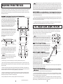
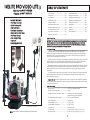
IKELITE PRO VIDEO-LITE 3
#6341.05 100-WATT VERSION
#6341.55 50-WATT VERSION
PACKAGE INCLUDES:
• Pro Video-Lite Head
• NiMH Battery Pack
• Ball Socket Arm
• Cord w/In-Line Switch
• Single Battery Pack Pouch
• Pro Video Charger
• Four charger Plugs
• Lubricant
• Mountiing Hardware
TABLE OF CONTENTS
Safety Notice............................................. Pg. 2
Introduction............................................... Pg. 2
Specifications............................................. Pg. 2
NiMH Battery Pack................................... Pg. 3
Using the Charger..................................... Pg. 4
Charging the Battery Pack....................... Pg. 4
Mounting the Battery Pack..................... Pg. 5-6
Lite Head and Arm System...................... Pg. 6
Cord with In-Line Switch.......................... Pg. 7
Mounting the Switch................................ Pg. 7
Connecting the Cord................................. Pg. 7
Opening the Lite Head............................. Pg. 8
Replacing the Primary Bulb..................... Pg. 9
Replacing the Modeling Bulb.................. Pg. 9
Sealing the Lite Head............................... Pg. 9
Maintenance.............................................. Pg. 10
Lubricant.................................................... Pg. 10
Accessories................................................. Pg. 11
Limited Warranty..................................... Pg. 12
SAFETY NOTICE________________________________________________________________
DANGER: The Pro Video-Lite’s battery pack should never be secured directly to the diver because
its cord connects to the lite head that will be secured to the video housing. In the event of an
emergency, the diver would be unable to free him/herself from the video housing, creating an
extremely dangerous, potentially life threatening situation.
INTRODUCTION________________________________________________________________
Normally, images recorded underwater have a blue-green cast because water absorbs the
warmer colors from the ambient light. The Ikelite Pro Video-Lite 3 helps you add the important
dimension of color to your recorded images. Turn on the Pro Video-Lite and your subjects will
“pop-out” from the background in living color.
Ikelite’s Pro Video-Lite features an ultra-compact light head incorporating a 50-watt or 100-watt
primary light and a 20-watt modeling light. Unsurpassed performance is achieved with an ultrawide 100° angle of coverage that is free of hot spots with 3400°K color temperature.
Although designed for use with all of Ikelite’s newer video housings, the Pro Video-Lite provides
the best buoyancy control with smaller housings weighing less than 8kg (17lbs). The battery pack
slides quickly and easily into a battery pouch underneath the housing, providing good weight
distribution.
The battery pack accepts one or two lite heads. Since close-up subjects may need less light than
distant subjects, add a second light head with appropriate wattage for dual intensity choices.
(See “Accessories” on page 11.)
Caution: Do not use the Pro Video-Lite above water. This product is not designed for extended
above water use. Water helps cool the lite head. Using the Video-Lite above water could overheat
the system and damage it.
SPECIFICATIONS_______________________________________________________________
Items shown are not to scale
Note: Please read all instructions before using this product.
Battery Power....................................................... 13.5-volt / 4.5 amp-hour NiMH
Battery Pack Recharge Time............................... 5 hours
Average Burn Time (One Battery Pack)............ 25 minutes with 100-watt lamp-bulb
55 minutes with 50-watt lamp-bulb
Coverage Angle (Primary Light)......................... 100° for primary lamp bulb
Color Temperature............................................... 3400° Kelvin
System Weight In Air........................................... 2.4 kg (5.3 lbs.)
System Weight Underwater................................ 0.9 kg (2.0 lbs.)
Depth Rating......................................................... 90 meters (300”)
Lite Head Size....................................................... 13.5cm x 6.6cm x 5.6cm (5.3” x 2.6” x 2.2”)
Battery Pack Size.................................................. 11.4cm x 16.5cm x 3.6cm (4.5” x 6.5” x 1.4”)
2
NiMH BATTERY PACK #1400.8
Caution: The battery pack is factory sealed. Do not disassemble. Disassembly will void your
Ikelite product’s limited warranty.
The rechargeable battery pack consists
of nickel metal hydride batteries (4.5 Ah
rating). Per charge, the pack can power
the primary light for 25 minutes with
a 100W lamp-bulb or for 55 minutes
with a 50W lamp-bulb (both times are
the tested average).
Single Battery Pack Pouch
Two lite heads can be connected to
the battery pack for greater intensity
or for dual 100W / 50W intensity choices.
(See “Accessories” on page 11.)
USING THE CHARGER
NOTE:_____________________________________________________
The Ikelite 10 Cell/12 Volt Pro / SpD
Smart Charger is not compatable
with the NiMH Battery Pack #1400.8
PRO / SpD CHARGER #1403.4____________________________________________________
The Ikelite Pro / SpD Charger #1403.4 is compatible with
the NiMh Battery Pack #1400.8 featured on the Ikelite
SpD and Pro Video-Lite systems (it is also compatible
with the older NiCad Battery Pack #1400).
Two battery packs can be stacked
in a double battery pack pouch and
connected to two lite heads. Or you
could attach two packs to one lite head
and double its run time.
(See “Accessories” on page 11.)
Double Battery Pack Pouch
Note:
• This charger is not compatible with Ikelite substrobes.
• Charger cords (#0171.61, #0171.62, #0171.63) for the
original smart chargers (#1403.1, #1403.2, #1403.3) are
not compatible with the Pro / SpD Charger #1403.4.
FRONT VIEW
BACK VIEW
CHARGING THE BATTERY PACK__________________________________________________
Warning: Do not attempt to charge the battery pack when it is still wet. Electrical shock,
injury, or fire could occur. Make sure all components are completely dry.
Charge the battery pack after purchase and recharge after each use.
The charger can be plugged into either of the two female connectors on the battery pack. To
charge the pack, please read the following instructions:
Vent on Back
of Pack
Waterproof Cap
Female Connector
(Cap Removed)
1. Make sure all components are dry. Rotate the lite head switch to the OFF position.
2. Unscrew and remove the waterproof cap or lite head cable.
3. Align the plug of the charger with the female connector on the battery pack and insert.
4. Screw the knurled ring of the plug down onto the female connector. Make sure the
connection is good and secure.
Caution: The battery pack’s female connectors are not waterproof and must be capped when
not connected to an Ikelite cord (i.e. the lite head’s cord with in-line switch). Using a battery pack
underwater with one or both of the female connectors uncapped or unconnected to a cord will
cause the pack to flood. Do not reuse a battery pack that has flooded. (See “Flooding” on page 10.)
Caution: Do not block or tamper with the vent on the battery pack. Normal evolution of all
batteries includes the emission of hydrogen gas. This gas must be absorbed or allowed to escape
to prevent ignition of the entrapped hydrogen/air mixture. A hydrogen absorber has been installed
inside the battery pack for this reason. The vent port on the battery pack allows hydrogen/air
mixtures to escape. The Ikelite battery pack pouch safely covers this vent.
5. Plug the charger into the wall and charge the pack. See the charger instructions for
details on charging times.
6. After charging, replace the waterproof cap.
You can tell it’s past time to recharge the pack by examining the intensity of the light. If it dims,
the batteries have been nearly depleted.
Caution: Do not completely drain (fully discharge) the battery pack. Fully discharging
the NiMH batteries will shorten the battery pack’s life.
Store the battery pack fully charged. Remove it from storage every few months and fully
recharge it.
Note: See charger instructions for further information.
3
4
MOUNTING THE BATTERY PACK
The battery pack is designed to slip quickly and easily into the battery pack pouch underneath
the housing. This pouch, secured via the battery plate, will effectively replace the existing
base of your Ikelite video housing. To remove the base and attach the pouch, please read the
following instructions.
REMOVING THE BASE AND ATTACHING THE BATTERY PACK POUCH________________
1. Carefully turn the video housing upside down on
a flat surface. Flip the toggle lever up and turn it
90°. Pull up to fully remove the base from the housing tray. Remove housing from tray by disconnecting
nuts with socket wrench and removing washers.
(If your housing has an aluminum base with lead
weight, see the “Adding Weight” section after
completing the rest of these instructions.)
2. With the housing tray still upside down, take
a mounting nut and place it flat against the opposite side of the housing tray with the stem of the
nut pushed up through the track in the middle of
the tray; the nut should have its flat portion
pointing towards the center of the tray.
(See diagram.)
Housing Tray
e-Clip
e-Clip
Battery
Pack Pouch
(Flap Open)
(Single Version
Shown)
Mounting
Screw
Mounting
Screw
3. Holding the nut in place with one hand, position
an e-clip against the stem of the nut; the points of
the e-clip should be pointing towards the center of
the tray. Using pliers, gently guide the three points
of the clip into the groove of the nut’s stem.
(See diagram.)
Caution: You are not attempting to crimp the
e-clips with the pliers; you are simply moving them
Two Female
to “lock” into place with the grooves of the
Connector
mounting nuts.
4. Repeat step #3 for the other mounting nut and e-clip. Reattach housing to tray.
NiMH
Battery
5. Open the flap of the battery pack pouch and slide the battery plate in so that the holes of the
pouch and the plate are aligned and so the textured side of the plate is pointed towards the Ikelite
logo on the bag.
6. With the video housing upside down, place the pouch against the bottom of the camera tray
so that the ventilated, Ikelite logo side of the bag is pointed towards you. The flap can be pointed
towards the back or the front of the housing, depending on your preference.
7. Drop the two mounting screws into the holes of the pouch and work them through the holes
of the plate and then through the holes on the opposite side of the pouch. Thread them into the
mounting nuts resting in the track of the housing tray.
8. Using a Philips Head screwdriver, securely tighten the two mounting screws.
5
(Continued on page 6.)
The Ikelite Lite Head connects to the Ikelite SA-100 Ball Socket Arm System. The system, in
turn, connects to either the bottom of the tray or top of the handle on of the video housing.
The ball socket arm system is compact, lightweight, and offers
Lite Head
flexibility in where you position the lite head.
+
+
Caution: The lite head’s female connector is not waterproof
and must be capped when not connected to an Ikelite cord (i.e.
the cord with in-line switch). Using the lite head underwater
with the female connector uncapped or unconnected to a cord
+
will cause the lite head to flood. (See “Flooding” on page 10.)
Female
Mounting Slot
MOUNT THE LITE HEAD TO THE ARM_____________
Connector
(Cap Removed)
Slide the arm’s ball mount into the mounting slot on the
bottom of the lite head. Push the mounting bolt through the
Ball Mount
Top of
hole in the ball mount and
thread
Arm
Wing
Nut into the lite head. Using a
Ball Clamp
flat head screwdriver, screw the mounting bolt completely
Washer
into the base of the lite head
until it is securely fastened.
Wing
Mounting Bolt
ATTACH THE ARM TO THE HOUSING____________
Nut
The tray mount on the arm can be connected to either
the top or bottom of a housing handle. Decide which end
Arm Extension
you’d prefer, then unscrew the black wing nut and
remove the washer from that section of the handle. Slide the proTray Mount
truding bolt of the handle through
Ball Clamp
the hole in the arm’s tray mount;
the ridged side of the tray mount
Wing Nut
should be resting against the handle. Return the washer to its place around the bolt and place it over the tray mount. Retighten the
wing nut onto the bolt toBolt
secure the mount.
+
Mounting Nut
(Secured with e-clip)
After removing the lead filled base and attaching the battery pack and the rest of the Pro VideoLite system, you may have a video housing that’s slightly positively buoyant underwater. This is not
ideal when diving and shooting photos.
LITE HEAD AND ARM SYSTEM
Mounting Nuts
Battery
Plate
Housing Tray
(Upside down)
ADDING WEIGHT (Connecting the Pro Video-Lite 3 to Ikelite Housings with Lead Weight Bases)
If your Ikelite housing features an aluminum quick-release base incorporating lead weight, please
read the following instructions:
To regain neutral bouyancy, you may need to purchase a Double Battery Pack Pouch and place
a weight inside along with the battery pack. (See “Accessories” on page 11.)
e-Clip
Mounting Nut
Note: Should you ever want to remove the battery pack pouch to replace it with the video housing’s original base, the position of the tray’s new mounting nuts will change depending on the age of
your video housing. Older style housings will need to have the tray’s mounting nuts pushed inwards
towards the center of the track, with the housing’s mounting nuts projecting through the ends of the
track. Newer style housings will have the tray’s mounting nuts pushed outwards towards the ends of
the track, with the housing’s mounting nuts projecting through the center of the track.
TURN ON THE LITE HEAD AND AIM_____________________________________________
Caution: Do not use the ProVideo-Lite above water. The water helps cool the lite head. Using the
Video-Lite above water could overheat the system and damage it.
Turn the primary lightHandle
bulb on underwater. Loosen the wing nuts on the ball clamps to manipulate the arm and lite head. Adjust the positioning to suit your needs. Retighten the wing nuts when
you have everything set up to your satisfaction.
Turn the modeling light on underwater. Look through the camera’s viewfinder and aim the lite
head so that the modeling light shines into the center of your picture area. If your subject’s distance
greatly changes, you should recheck the aim of the lite head.
6
Tray
OPENING THE LITE HEAD
CORD WITH IN-LINE SWITCH
OPENING THE LITE HEAD_______________________________________________________
An in-line switch is featured on the cord that connects the battery pack to the lite head.
There are three positions on the On/Off switch:
Note: It is only necessary to open the lite head when a bulb needs to be replaced.
• The center position on the switch is OFF.
• Rotate the switch counterclockwise to turn on the primary light bulb.
• Rotate the switch clockwise to turn on the modeling light bulb.
Warning: Allow the bulbs in the lite head to cool down sufficiently; they reach very high temperatures during operation. Wait at least 15 minutes before opening the lite head. Prematurely opening
the lite head could burn you.
Note: It is not possible to have both lights on at the same time on one lite head.
Warning: Never look into the face of the lite head when it is on. Its intensity could temporarily
blind and/or disorient you.
MOUNTING THE SWITCH____________________________
Two
The switch mounts to the top or bottom of the contoured Connector
handle on the Ikelite housing. It is recommended that the
Cords
switch assembly be positioned with the On/Off switch
pointed down for easier fingertip operation.
To mount the switch, unscrew the wing nut and remove the
washer from the top or bottom of one handle. Slide the now
exposed handle bolt through the hole in the mount of the On/Off
switch assembly. Replace the washer and then tighten the wing
nut over it to secure the switch assembly in place.
On/Off
When using dual lite heads, switches can be mounted to the top
Switch
or bottom of one or both handle assemblies. In such cases, you may
prefer to have one or both switches pointed up instead of down.
CONNECTING THE CORD______________________________________________
Either of the two female connectors on
the battery pack can be used to connect
the cord with in-line switch to the lite head.
Retaining
Stem O-ring
Turn the switch to OFF and make sure
Ring
all parts are dry. Remove one waterproof
bulkhead cap from the battery pack to access a female connector. Unscrew and
remove the dust caps from the ends of the in-line switch’s two connector cords.
Wing Nut
Note: The seal ring does not need lubrication.
Washer
Mount
Bolt
Lite Head
Cover
Handle
Plex Window
Tray
Caution: It is important to keep the connector threads on the battery pack
and the lite head clean and lightly lubricated. Otherwise, it’s possible for the cord to become stuck
Cordand
With
In-Line
Switch
on a connector. Also keep the in-line switch cord’s o-rings and threads clean
lightly
lubricated.
Regularly check these o-rings for nicks or cuts. These actions will prevent your cord from flooding.
(See “Lubricant” on page 10 for more information.)
Reflector
Cover Plate
Wing Nut
Both ends of the cord are identical; either end can be connected to the lite head or battery pack.
Note the positioning of the receptacles and pins on the ends of the two connector cords; properly
align the cord and insert one cord into the lite head and the other into the battery pack. Then,
working with one cord at a time, begin hand-tightening the knurled retaining ring while carefully
pushing the pins and receptacles further into the female connector. Continue tightening the
retaining ring until the cord is securely fastened. Repeat this for the remaining cord.
Caution:
• Do not leave the cord connected for extended periods of time. Electrolysis could occur and make
removal of the cord impossible.
• Do not disconnect the cord underwater or when wet. Connections are not waterproof and must
be capped when not connected.
7
1. Turn the cord’s in-line switch to OFF and disconnect the cord from the lite head.
2. Using a Philip’s head screwdriver, loosen and remove the four screws on the front of the lite
head cover. Carefully remove the cover and the clear plex window beneath it; the window is not
permanently secured to the cover.
3. Note the positioning of the seal ring on the lite head. Make sure the seal ring and sealing surface
is clean of dirt and debris. Remove the seal ring.
Lamp Holder
Seal Ring
Center Mount
Modeling
Light
Primary Bulb
Flat Section
Mounting Slot
8
Female Connector
(Cap Removed)
REPLACING THE BULBS
REPLACING THE PRIMARY BULB ________________________________________________
(Primary 50W bulb #0049.50 or 100W bulb #0049.51)
Caution: Avoid touching the surface of the bulb with your fingers. Oil and dirt from your fingers
will create heat concentrations that will shorten the bulb’s life.
1. Make sure the bulbs are cool.
2. Loosen and remove the two screws that secure the reflector cover plate over the modeling light.
3. Using needle nose pliers, gently grasp the center mount of the lamp holder and lift it partially
out of the light head; be careful, the wires will be attached to the inside of the head. Using a soft
cloth or tissue, gently grasp the flat section of the used bulb and pull it straight out of the holder.
Discard the used bulb.
4. Using a soft cloth or tissue, gently pick up the new, replacement bulb. Align the bulb’s two pins
with the holes of the lamp holder and push carefully from the back to insert the bulb. Once fully
inserted, there will be a small section of exposed pins between the base of the bulb and the lamp
holder.
5. With the pliers gently clasping the center mount, ease the lamp holder back into the lite head.
REPLACING THE MODELING BULB_______________________________________________
(Modeling 20W bulb/reflector combination #0049.42)
Caution: Avoid touching the surface of the bulb with your fingers. Oil and dirt from your fingers
will create heat concentrations that will shorten the bulb’s life.
1. Make sure the bulbs are cool.
2. Loosen and remove the two screws that secure the reflector cover plate over the modeling light.
3. Using needle nose pliers, gently grasp the center mount of the lamp holder and lift it partially
out of the light head; be careful, the wires will be attached to the inside of the head.
4. Grasp the back of the used modeling light bulb/reflector combination and pull the reflector
straight out of the lamp holder. Discard the used bulb.
5. Using a soft cloth or tissue to protect the inside of the reflector, pick up the new modeling bulb
and align the two pins with the holes in the lamp holder. Insert.
6. With the pliers gently clasping the center mount, ease the lamp holder back into the lite head.
SEALING THE LITE HEAD________________________________________________
1. Make sure the lamp holder is fully resting in the back of the lite head. Do not touch the bulbs
or reflector in the process. Position the metal reflector cover plate over the modeling light. Thread
the two small screws through the reflector cover plate and tighten with a Philip’s head screwdriver
to secure it in place.
2. Make sure the seal ring and sealing surface is clean of dirt and debris. Center the seal ring on
the lite head. Note: Again, no lubrication of the seal ring is needed.
3. Make sure the clear plex window is resting inside the lite head cover. Place the cover and window
on the front of the lite head with the larger, oval opening over the primary bulb.
4. Thread the four larger screws into the front of the lite head cover. Firmly tighten each screw
with a Philip’s head screwdriver, one at a time.
9
MAINTENANCE
Ikelite recommends adding an ALL RISK FLOATER to your homeowner’s or renter’s insurance policy
to cover your Ikelite video system against loss, damage, or flooding. Ikelite’s warranty does not
cover customer neglect.
Caution: Make sure all female connectors are covered with bulkhead caps or cord connections
before exposing the system to water, whether diving or cleaning. Water should never enter the battery pack or lite head. If this does occur, see the “Flooding” section on this page.
Regular visual inspections are important to the maintenance of this system. A forgotten o-ring
can cause a lot of damage, for example.
ROUTINE CLEANING____________________________________________________________
• Rinse the Pro Video -Lite 3 system with fresh water after each use, especially after exposure to
salt water. While rinsing, turn the in-line switch to free salt or debris that might have accumulated
in its recesses during the dive.
• Keep the threads of the female connectors on the battery pack and the lite head clean and lightly
lubricated. Keep the system’s o-rings and sealing surfaces clean of dirt and debris, being careful not
to stretch the o-rings when removing them for cleaning and lubrication. See “Lubricant” for more
information.
Caution: Do not lubricate the seal ring on the lite head, as this may cause the lite head to leak
underwater.
LONG TERM STORAGE__________________________________________________________
• Submerging the Pro Video-Lite 3 system in a body of warm, soapy water will clean its exterior;
let it soak for an hour or two. Use a liquid soap and thoroughly rinse the system afterwards.
• Thoroughly dry all parts of the Pro Video-Lite 3 before putting the system in storage. This
includes the lite head, battery pack, arm system, and cord.
• Disconnect the cord with in-line switch from the battery pack and lite head when in storage.
• The battery pack should be put into storage fully charged and should be fully recharged every
few months. The female connectors should be capped when in storage.
• Dim or yellow light indicates that it’s time to recharge the battery pack. Do not completely drain
(discharge) the battery pack; it may shorten the pack’s life.
LUBRICANT____________________________________________________________________
• Silicone lubricant is provided. Use only enough lubricant to make the area where it’s being
applied feel slick; wipe off any excess with a clean cloth.
• Use only Ikelite brand silicone lubricant with Ikelite brand o-rings; other brand lubricants can
cause the Ikelite o-rings to swell in size.
• Lubricant only reduces friction; it is not a sealant.
• Caution: Do not use spray lubricant; it can crack the plastic of the system.
FLOODING_____________________________________________________________________
In the event of flooding, do not attempt to repair your Ikelite Pro Video-Lite III system yourself.
Gather all of the system’s components and return them to Ikelite for inspection, water pressure
testing, and/or repair.
Caution: Do not reuse batteries that have been wet; the water could create an internal short
circuit at some later date, potentially causing an explosion. In case the battery pack floods, return
it to Ikelite for repair along with the other system components.
10
ACCESSORIES
PRO VIDEO-LITE HEAD__________________________________________________________
Add a second lite head for more intensity overall or for dual 50W / 100W intensity choices
(like when looking at close-up subjects that need less light than distant subjects). Choose from the
following lite head packages:
100W #6386.1 (Lite head w/ 100W bulb)
50W #6386.51 (Lite head w/ 50W bulb)
Both packages include a cord w/ in-line switch and a 15cm (6”) mounting arm.
LIMITED WARRANTY
All Ikelite products are warranted against any manufacturing defects for a period of
one year from the date of purchase. Defective products should be returned prepaid to
Ikelite. Ikelite will, at its discretion, repair or replace such products, and will return to
customer prepaid. All other claims, of any nature, including, but not limited to, bulb
failure are not covered. Except as mentioned above, no other warranty expressed or
implied, applies to this Ikelite product.
PRO VIDEO-LITE BATTERY PACK #1400.8_________________________________________
Additional battery packs are available. A spare battery pack is helpful when you quickly need to
replace an exhausted pack above water. Two battery packs can be stacked and each connected to
a separate lite head. Alternatively, you can use only one lite head and connect two staked battery
packs for twice the runtime. (Stacking packs requires Double Battery Pack Pouch. Connecting packs
require Battery Cable.)
#1400.8 NiMH Battery Pack
#1401.2 Double Battery Pack Pouch
#1405.06 Battery Cable
REPLACEMENT BULBS__________________________________________________________
Primary bulb:
50W #0049.50
100W #0049.51
Modeling bulb: 20W #0049.42
ARM SYSTEM___________________________________________________________________
The ball socket arm system is easily adaptable. The following components are available for
puchase to help customize your arm system.
IKELITE UNDERWATER SYSTEMS
50 West 33rd Street
PO Box 88100
Indianapolis, IN 46208 USA
317-923-4523
www.ikelite.com
Email [email protected]
#0466.42
10 cm (4”) Ball-to-Ball
Arm Extension
#0466.62
15cm (6”) Ball-to-Ball
Arm Extension
#0466.92
23cm (9”) Ball-to-Ball
Arm Extension
11
#9571.2 - Ball Clamp
12
6341.05-06-0307