1
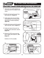
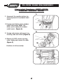
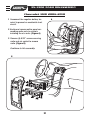
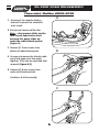
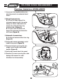
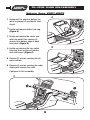
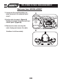
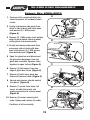
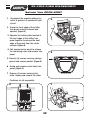
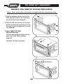
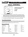
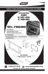
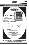
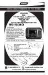
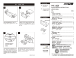
INSTALLATION INSTRUCTIONS FOR PART 95-3302
APPLICATIONS
GM
MULTI KIT
(see models list inside)
95-3302
KIT FEATURES
• Double DIN Mount Radio Provision
• Stacked ISO Mount Radio Provision
• Painted To Match Factory Dash
KIT COMPONENTS
A) Double DIN Housing • B) Double DIN Brackets
B
A
WIRING AND ANTENNA CONNECTIONS (Sold Separately)
Wiring Harness:
• See www.metraonline.com for specific interface applications
Antenna Adapter:
• 40-GM10 - GM antenna adapter 1988-up
• 40-CR10 - Chrysler antenna adapter 2002-up
TOOLS REQUIRED:
Small Flat Blade Screwdriver/ Panel Removal Tool
• Phillips Screwdriver • Socket Set • Cutting Tool
1-800-221-0932
www.metraonline.com
© COPYRIGHT 2004-2009 METRA ELECTRONICS CORPORATION
95-3302
TABLE OF CONTENTS
Dash Disassembly
Chevrolet
Saturn
- Cobalt 2005-2010 . . . . . . . . . . . . . . . .1
- Aura 2007-2009 . . . . . . . . . . . . . . . . . . 9
- Equinox 2005-2006 . . . . . . . . . . . . . 2
- HHR 2006-2010. . . . . . .. . . . . . . . . . . . 3
- Malibu 2004-2007 . . . . . . . . . .. . . . .4,5
- Malibu 2008-2010 . . . . . . . . . . .. . . . .6
- Ion 2006-2007 . . . . . . . . . . . . . . . . . . .10
- Sky 2006-2009 . . . . . . . . . . . . . . . . . . .11
- Vue 2006-2007 . . . . . . . . . . . . . . . . . . . 12
Pontiac
- G5 2007-2009 . . . . . . . . . . . . . . . . . . . . 1
- G6 2005-2009 . . . . . . . . . . . . . . . . . . . . 7
- Solstice 2006-2009 . . . . . . . . . . . . . . . 8
- Torrent 2006. . . . . . . . . . . . . . . . . . . . . . 2
Kit Assembly
Double DIN Mount Radio Provision . . . . . . . . . . . . . . . . . . . . . . . . . . . . . . . . . . . . . . . . . . . . . . . . . 13
Stacked ISO Mount Radio Provision . . . . . . . . . . . . . . . . . . . . . . . . . . . . . . . . . . . . . . . . . . . . . . . . 14
Final Assembly . . . . . . . . . . . . . . . . . . . . . . . . . . . . . . . . . . . . . . . . . . . . . . . . . . . . . . . . . . . . . . . . . 15
Note: (Cobalt and G5 2005-2006)
To retain Onstar use 99-3303 instead.
Note: (Malibu and G6 only)
•The Driver Information Center and radio are one unit. Removal of the radio
will prohibit the vehicle owner from programming any of the features of the
Driver Information Center. However once the features are programmed the
vehicle will retain all the settings. An alternative kit 99-3303 inludes a
replacement driver information center with programming capabilities.
The 99-3303 does not allow for Double DIN installations.
• Refer also to the instructions included with the aftermarket radio.
KNOWLEDGE IS POWER
Enhance your installation and fabrication skills
by enrolling in the most recognized and
respected mobile electronics school in our
industry.
Log onto www.installerinstitute.com or call
800-354-6782 for more information and take
steps toward a better tomorrow.
95-3302 DASH DISASSEMBLY
Chevrolet Cobalt 2005-2010/Pontiac G5 2007-09
A
1 Disconnect the negative battery terminal to prevent an accidental short
circuit.
2 Unclip and remove trim panel from
above glove box. (Figure A)
3 Unclip upper edge of panel below
steering column and let hang. Not
necessary to remove completely.
(Figure B)
B
4 Unclip and remove small trim panel to
right of ignition switch. (Figure C)
5 Unclip and remove trim panel surrounding radio and climate controls.
(Figure D)
C
6 Remove (4) 9/32 screws securing
radio. Unplug and remove the radio.
(Figure E)
Continue to kit assembly.
E
D
1
95-3302 DASH DISASSEMBLY
Chevrolet Equinox 2005-2006
Pontiac Torrent 2006
A
1 Disconnect the negative battery terminal to prevent an accidental short
circuit.
2 Unsnap panel below power window
switch and remove. Note: This
allows you to unplug the window
switch easier. (Figure A)
B
3 Unsnap and remove entire panel surrounding radio and shifter. (Figure B)
4 Remove (4) 9/32 screws securing
radio. Unplug and remove the radio.
(Figure C)
Continue to kit assembly.
C
2
95-3302 DASH DISASSEMBLY
Chevrolet HHR 2006-2010
A
1 Disconnect the negative battery terminal to prevent an accidental short
circuit.
2 Unclip and remove entire panel surrounding radio and a/c controls
including the a/c vents. (Figure A)
3 Remove (8) 9/32” screws securing
radio and a/c control to remove
radio. (Figure B)
Continue to kit assembly.
B
3
95-3302 DASH DISASSEMBLY
Chevrolet Malibu 2004-2007
A
1 Disconnect the negative battery terminal to prevent an accidental short
circuit.
2 Unclip and remove wood grain/painted trim pieces from both sides of
steering wheel. (Figure A)
3 Unclip and remove side panel from
driver’s side of dash with door open
and remove (2) 7 MM screws.
(Figure B)
B
4 Remove (2) 7 MM screws from bottom edge of panel below steering
wheel, unclip panel and let hang. It
is not necessary to completely
remove panel. (Figure C)
C
5 Unclip and remove wood
grain/painted trim piece from above
glove box. (Figure D)
D
4
95-3302 DASH DISASSEMBLY
Chevrolet Malibu 2004-2007
E
6 Unclip and remove side panel from
passenger side of dash with door
open and remove (2) 7 MM screws
from behind panel. (Figure E)
7 Remove (2) 7 MM screws from bottom of glove box then open box and
squeeze sides together to open further and remove the remaining (4)
7MM screws. Unclip the black vent
cover under the glove box then unclip
and remove entire glove box assembly. (Figure F)
F
8 Unclip and remove trim panel surrounding radio and climate controls.
(Figure G)
9 Remove (4) 7 MM screws securing
the radio and (2) 7 MM screws securing the climate control. Unplug and
remove the radio. (Figure H)
G
Continue to kit assembly.
H
5
95-3302 DASH DISASSEMBLY
Chevrolet Malibu 2008-2010
A
1 Disconnect the negative battery
terminal to prevent an accidental
short circuit.
2 Unsnap and remove shifter trim.
Note – start around shifter and be
sure to pull down before back
because this panel slides up
under the radio/climate panels.
(Figure A)
3 Remove (2) 8 mm screws from
bottom of radio/climate panel.
B
4 Unsnap and remove the climate/radio
panel and upper vent trim panel
together. (They can be separated after
removel) (Figure B,C)
5 Remove (6) 8 mm screws from
radio and climate controls.
Continue to kit assembly.
C
6
95-3302 DASH DISASSEMBLY
Pontiac G6 2005-2009
A
1 Disconnect the negative battery terminal to prevent an accidental short
circuit.
2 Open glove box and remove (6)
screws from outer edge then unclip
and remove box. (Figure A)
3 Remove (4) screws from panel
below steering column. Unclip and
remove panel. (Figure B)
B
4 Unclip and remove center panel surrounding radio and A/C controls.
(Figure C)
5 Remove (4) screws securing the radio.
Unplug and remove the radio.
(Figure D)
C
Continue to kit assembly.
D
7
95-3302 DASH DISASSEMBLY
Pontiac Solstice 2006-2009
A
1 Disconnect the negative battery terminal to prevent an accidental short
circuit.
2 Manual transmission:
A. Lift up the lower edge of the
instrument panel cluster trim plate
enough to reach underneath and
release the shift boot trim ring
retaining tabs. (Figure A)
B. Lift up on the shift boot and
loosen the setscrew to release the
shift lever. (Figure B)
B
2 Automatic transmission:
A. Unclip and remove shifter trim ring.
(Figure C)
3 Unclip and remove passenger assist
handle trim panel. (Figure D)
C
4 Remove (2) bolts securing the passenger assist handle and remove
handle. (Figure D)
5 Unclip and remove dash trim panel.
6 Remove (4) screws securing the radio.
Unplug and remove the radio.
Continue to kit assembly.
D
8
95-3302 DASH DISASSEMBLY
Saturn Aura 2007-2009
A
1 Disconnect the negative battery terminal to prevent an accidental short
circuit.
2 Unclip and remove shifter trim ring.
(Figure A)
3 Unclip and remove the center console trim panel, then remove (2)
screws from bottom edge of dash
trim panel. (Figure B)
B
4 Unclip and remove the key switch
trim ring, then unclip and remove
dash trim panel. (Figure C)
5 Remove (2) screws securing the climate controls.
6 Remove (4) screws securing the radio.
Unplug and remove the radio.
Continue to kit assembly.
C
9
95-3302 DASH DISASSEMBLY
Saturn Ion 2006-2007
1 Disconnect the negative battery terminal to prevent an accidental short
circuit.
A
2 Unclip radio trim panel. (Figure A)
Unplug connectors from trim panel and
remove panel. (Figure B)
3 Remove (4) screws securing the
radio. Unplug and remove the radio.
B
Continue to kit assembly.
10
95-3302 DASH DISASSEMBLY
Saturn Sky 2006-2009
A
1 Disconnect the negative battery terminal to prevent an accidental short
circuit.
2 Unclip and remove side panel from
driver’s side of dash with door open
and remove (2) 7 MM screws.
(Figure A)
3 Remove (2) 7 MM screws from bottom
edge of panel below steering wheel,
unclip panel and remove panel.
B
4 Unclip and remove side panel from
passenger side of dash with door
open and remove (2) 7 MM screws
from behind panel. (Figure B)
5 Open the glove box and disconnect
the glove box dampener from the
glove box assembly. Squeeze sides
together to open further. (Figure C)
C
6 Remove (2) bolt covers from top
edge of glove box frame. (Figure C)
7 Remove (5) bolts from glove box
frame and remove frame. (Figure C)
8 Unsnap and remove climate control
trim panel. (Figure D)
9 Remove (1) screw from lower left
corner of radio trim panel and
unplug connectors to remove panel.
(Figure D)
D
10 Remove (4) screws securing the
radio. Unplug and remove the radio.
Continue to kit assembly.
11
95-3302 DASH DISASSEMBLY
Saturn Vue 2006-2007
1 Disconnect the negative battery terminal to prevent an accidental short
circuit.
A
2 Grasp the front edge of the shifter
trim panel and pull outward and
upward. (Figure A)
3 Squeeze the locking tabs located at
the front edge of the shifter trim
panel together to release the front
edge of the panel from the center
console. (Figure B)
4 Pull upward on the panel to release
the remaining clips, and remove trim
panel.
B
5 Remove (4) screws securing storage
pocket and remove pocket. (Figure C)
6 Unclip and remove center dash trim
panel. (Figure D)
7 Remove (4) screws securing the
radio. Unplug and remove the radio.
BOTTOM VIEW
Continue to kit assembly.
C
D
12
95-3302 KIT ASSEMBLY
DOUBLE DIN MOUNT RADIO PROVISION
*Note: Refer also to the instructions included with the aftermarket radio.
A
1 Slide the appropriate bracket into the trim
plate aligning the holes in the trim plate to
the clips on the bracket. (Figure A)
2 Slide the DDIN radio unit into the trim plate
bracket assembly and secure the unit to the
kit using the screws supplied with the head
unit. (Figure B)
3 Aura, Cobalt, G5, HHR,
Sky and Vue only:
Cut and remove top mounting tabs on
each side of the Radio Housing.
(Figure C)
B
Continue to final assembly.
C
13
95-3302 KIT ASSEMBLY
STACKED ISO MOUNT RADIO PROVISION
*Note: Refer also to the instructions included with the aftermarket radio.
A
1 Slide the appropriate bracket into the trim
plate aligning the holes in the trim plate to
the clips on the bracket. (Figure A)
2 Slide the stacked ISO DIN units into the trim
plate bracket assembly and secure the units
to the kit using the screws supplied with
the head units. (Figure B)
3 Aura, Cobalt, G5, HHR,
Sky and Vue only:
Cut and remove top mounting tabs on
each side of the Radio Housing.
B
Continue to final assembly.
C
14
95-3302 FINAL ASSEMBLY
FINAL ASSEMBLY
A
(A) Strip wire ends back 1/2"
B
B) Twist ends together
C) Solder
D) Tape
C
D
1
Locate the factory wiring harness in the dash. Metra recommends using the
proper mating adapter and making connections as shown. (Isolate and individually tape off the ends of any unused wires to prevent electrical short circuit.)
2
Re-connect the negative battery terminal and test the unit for proper operation.
3
Reassemble radio and dash assemblies in reverse order of disassembly.
FINAL WIRING CONNECTIONS
Make wiring connections using the EIA color code chart shown below and the instructions included with the
head unit. Metra recommends making connections as shown below; Strip, Splice, Solder, Tape. Isolate and
individually tape off ends of any unused wires to prevent electrical short circuit.
METRA / EIA WIRING CODE
12V Ignition / Acc. . . . . . . . . . Red
Right Front (+) . . . . . . . . . . . . Gray
12V Batt / Memory. . . . . . . . . Yellow
Right Front (-). . . . . . . . . . . . . Gray/ Black
Ground. . . . . . . . . . . . . . . . . . Black*
Left Front (+) . . . . . . . . . . . . . White
Power Antenna. . . . . . . . . . . . Blue
Left Front (-). . . . . . . . . . . . . . White / Black
Amp Turn-On . . . . . . . . . . . . . Blue / White
Right Rear (+) . . . . . . . . . . . . Violet
Amp Ground. . . . . . . . . . . . . . Black / White
Right Rear (-) . . . . . . . . . . . . . Violet / Black
Illumination . . . . . . . . . . . . . . Orange
Left Rear (+) . . . . . . . . . . . . . Green
Dimmer . . . . . . . . . . . . . . . . . Orange / White
Left Rear (-) . . . . . . . . . . . . . . Green / Black
*NOTE: When a Black wire is not present, ground radio to vehicle chassis.
All colors may not be present on all leads due to manufacturer’s specifications.
15
95-3302
NOTES
16
95-3302
NOTES
17
95-3302 INSTRUCTIONS
1-800-221-0932
www.metraonline.com
REV. 05/03/10 © COPYRIGHT 2001-2010 METRA ELECTRONICS CORPORATION INST95-3302