1
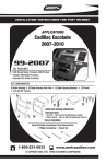
INSTALLATION INSTRUCTIONS FOR PART 99-3002
APPLICATIONS
CADILLAC/CHEVROLET/GMC
(See Inside For Specific Applications)
99-3002
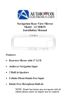
AT-300GM
AW-300GM
INSTALLATION INSTRUCTIONS
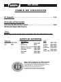
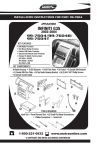
KIT FEATURES
• Shaft, DIN and ISO-DIN Unit Provisions
• Various Mounting Depth Alternatives
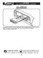
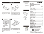
KIT COMPONENTS
• A) Radio Housing • B) Face Plate • C) Spacer • D) Snap Spacers • E) ISO-DIN Brackets
• F) (2) #6 Self Tapping Screws • G) (4) 5mm Flat Head Srews • H) Tape Strips
B
A
F
E
C
D
H
WIRING AND ANTENNA CONNECTIONS
(SOLD SEPARATELY)
HARNESS:
• 70-1858 - GM harness 87-05
ANTENNA ADAPTER:
• 40-GM10 - GM antenna adapter 88-up
G
TOOLS REQUIRED:
• Phillips Screwdriver • Socket Wrench • Cutting Tool
1-800-221-0932
www.metraonline.com
© COPYRIGHT 2001-2009 METRA ELECTRONICS CORPORATION
99-3002
TABLE OF CONTENTS
Kit Preparation . . . . . . . . . . . . . . . . . . . . . . . . . . . . . . . . . . . . . . . . . . . . . . . . 1,2,3
Kit Assembly and Final Assembly
Shaft Head Unit Mount Radio Provision . . . . . . . . . . . . . . . . . . . . . . . . . . . . . . . .4,5,6
DIN Head Unit Mount Radio Provision
*Note:
Refer also to the instructions included with the aftermarket radio.
APPLICATIONS
CADILLAC
Escalade 1999-2002
EXT
2002
CHEVROLET
Astro
1996-2005
Avalanche
2002
Express (Full size van)1996-2000
Pickup (C-Series)
1995-2000
Silverado
1999-2002
Suburban
1995-2002
Tahoe
1995-2002
GMC
Safari
Savana
Sierra
Suburban
Tahoe
Yukon (All)
KNOWLEDGE IS POWER
Enhance your installation and fabrication skills
by enrolling in the most recognized and respected
mobile electronics school in our industry.
Log onto www.installerinstitute.com
or call 800-354-6782 for more information
and take steps toward a better tomorrow.
1996-1995
1996-2000
1995-2002
1995-2002
1995-2002
1995-2002
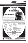
99-3002 KIT PREPARATION
CADILLAC
Escalade 1999-2002 / EXT 2002
CHEVROLET
Avalanche/Pickup/Suburban/Tahoe 1995-2002
Silverado 1999-2002
GMC
Sierra/Suburban/Yukon 1995-2002
A
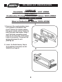
1 Disconnect the negative battery terminal to prevent an accidental short
circuit. Remove the steering column
filler panel and the ashtray. Unclip the
dash trim bezel and remove. Using a
small flat-blade screwdriver, press
down on the outer clips of the factory
head unit (or pocket). Disconnect the
wiring and remove the unit.
(See Fig. A)
2 Locate the Radio Housing. Skip to
the Installation Instructions for ALL
VEHICLES on Page #4.
B
1
99-3002 KIT PREPARATION
CHEVROLET
Express
GMC
Savana 1996-2002
A
1 Disconnect the negative battery terminal to prevent an accidental short
circuitt. Remove the steering column
filler panel and the ashtray. Unclip
the dash trim bezel and remove.
Using a small flat-blade screwdriver,press down on the outer clips of
the factory head unit (or pocket).
Disconnect the wiring and remove
the unit. (See Fig. A)
2 Locate the Radio Housing. Skip to
the Installation Instructions for ALL
VEHICLES on Page #4.
B
2
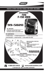
99-3002 KIT PREPARATION
CHEVROLET
Astro
GMC
Safari 1996-2005
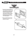
1 Disconnect the negative battery terminal to prevent an accidental short circuit.
Place the gear selector in its lowest position. Unclip the perimeter of the dash trim
bezel. Disconnect the rear a/c control harness and the headlight switch from the back
of the dash trim bezel and remove the bezel. Using a flat-blade screwdriver press
down on the outside clips of the factory head unit and remove. (See Fig. A)
A
B
2 Peel away the paper backings from
the Tape Strips and stick the Strips
to the lower shelves of the mounting
clips. Skip to the Installation
Instructions for ALL VEHICLES on
Page #4.
3
99-3002
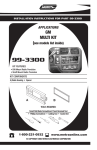
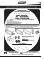
KIT ASSEMBLY/FINAL ASSEMBLY
ALL VEHICLES
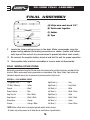
2-SHAFT HEAD UNITS: Snap the Faceplate into the Radio Housing. Slide the
aftermarket head unit into the kit and secure with shaft nuts. (See Fig. A)
ISO DIN HEADS UNITS: Cut and remove the shaft supports from the Faceplate.
Snap the Faceplate into the Radio Housing. Slide the aftermarket head unit into
the back of the kit. Slide the ISO-DIN Brackets onto the Housing legs and align the
holes in the Brackets with the holes in the unit. Mount the Brackets to the unit with
(4) 5mm Flat-head Screws supplied ("A"). Mount the Brackets to the top of the
Housing legs with (2) #6 Self-tapping Screws ("B"). (See Fig. B)
DIN HEAD UNITS: If a surface-mount installation is desired, cut and remove the
shaft supports from the Faceplate. Snap the Faceplate into the Radio Housing. Slide
the DIN cage into the kit and secure by bending the metal locking tabs down. Slide
the aftermarket head unit into the cage until secure. (See Fig. A). If an intermediate-mount installation is desired, attach the Snap Spacers to the outer walls of the
radio opening. Slide the DIN cage into the Radio Housing and secure by bending the
metal locking tabs down. Slide the aftermarket head unit into the cage until secure.
(See Fig. B). If flush-mount installation is desired, slide the DIN cage into the Radio
Housing and secure by bending the metal locking desired, slide the DIN cage into
the Radio Housing and secure by bending the metal locking tabs down. Slide the
aftermarket head unit into the cage until secure. (See Fig. C)
4
99-3002 FINAL ASSEMBLY
FINAL ASSEMBLY
A
(A) Strip wire ends back 1/2"
B
B) Twist ends together
C) Solder
D) Tape
C
D
1
Locate the factory wiring harness in the dash. Metra recommends using the
proper mating adapter and making connections as shown. (Isolate and individually tape off the ends of any unused wires to prevent electrical short circuit.)
2
Re-connect the negative battery terminal and test the unit for proper operation.
3
Reassemble radio and dash assemblies in reverse order of disassembly.
FINAL WIRING CONNECTIONS
Make wiring connections using the EIA color code chart shown below and the instructions included with the
head unit. Metra recommends making connections as shown below; Strip, Splice, Solder, Tape. Isolate and
individually tape off ends of any unused wires to prevent electrical short circuit.
METRA / EIA WIRING CODE
12V Ignition / Acc. . . . . . . . . . Red
Right Front (+) . . . . . . . . . . . . Gray
12V Batt / Memory. . . . . . . . . Yellow
Right Front (-). . . . . . . . . . . . . Gray/ Black
Ground. . . . . . . . . . . . . . . . . . Black*
Left Front (+) . . . . . . . . . . . . . White
Power Antenna. . . . . . . . . . . . Blue
Left Front (-). . . . . . . . . . . . . . White / Black
Amp Turn-On . . . . . . . . . . . . . Blue / White
Right Rear (+) . . . . . . . . . . . . Violet
Amp Ground. . . . . . . . . . . . . . Black / White
Right Rear (-) . . . . . . . . . . . . . Violet / Black
Illumination . . . . . . . . . . . . . . Orange
Left Rear (+) . . . . . . . . . . . . . Green
Dimmer . . . . . . . . . . . . . . . . . Orange / White
Left Rear (-) . . . . . . . . . . . . . . Green / Black
*NOTE: When a Black wire is not present, ground radio to vehicle chassis.
All colors may not be present on all leads due to manufacturer’s specifications.
5
99-3002
KIT ASSEMBLY/FINAL ASSEMBLY
ALL VEHICLES
Re-connect the battery terminal and test the unit for proper operation. Mount the head
unit/kit assembly to the sub-dash with those screws previously removed.
Enjoy your newly installed radio!
www.metraonline.com
1-800-221-0932
REV. 07/31/09 © COPYRIGHT 2001-2009 METRA ELECTRONICS CORPORATION INST99-3002
6