1
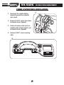
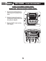
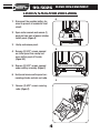
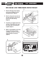
INSTALLATION INSTRUCTIONS FOR PART 99-5026
APPLICATIONS
Ford Mustang 2001-2004
Ford Expedition (w/o NAV) 2003-2006
Ford Explorer 2002-2005
Lincoln Navigator (w/o NAV) 2003-2006
Lincoln Aviator 2002-2005
Mercury Mountaineer 2002-2005
99-5026
KIT FEATURES
• DIN head unit provision with pocket
• ISO DIN head unit provision with pocket
KIT COMPONENTS
A) Radio Housing B) ISO Brackets C) Rear Support Bracket D) ISO Trimplate E) (1) #8 X 3/8” Phillips Truss Head Screw
A
B
C
D
E
WIRING AND ANTENNA CONNECTIONS (Sold Separately)
Harness:
• 70-5519 - Ford amplified harness 1998-08
• 70-5520 - Ford harness 2003-up
• 70-5521 - Ford amplified harness 2003-up
• 70-1771 - Ford harness 1998-up
Antenna Adapter:
• Not required
TOOLS REQUIRED:
Phillips Screwdriver • Socket wrench
1-800-221-0932
www.metraonline.com
© COPYRIGHT 2004-2009 METRA ELECTRONICS CORPORATION
99-5026
TABLE OF CONTENTS
Dash Disassembly . . . . . . . . . . . . . . . . . . . . . . . . . . . . . . . . . . 1-5
Kit Assembly . . . . . . . . . . . . . . . . . . . . . . . . . . . . . . . . . . . . . 6-7
Final Assembly . . . . . . . . . . . . . . . . . . . . . . . . . . . . . . . . . . . . . . . 8
KNOWLEDGE IS POWER
Enhance your installation and fabrication skills by
enrolling in the most recognized and respected
mobile electronics school in our industry.
Log onto www.installerinstitute.com or call
800-354-6782 for more information and take
steps toward a better tomorrow.
99-5026
DASH DISASSEMBLY
FORD MUSTANG 2001-2004
1
Disconnect the negative battery
terminal to prevent an accidental
short circuit.
2
Unclip and remove shift lever trim
panel. (Figure A)
3
Unclip and remove the entire panel
surrounding the radio and climate
controls including the vents.
(Figure B)
4
Remove (2) 9/32” screws securing
radio. (Figure B)
A
B
1
99-5026
DASH DISASSEMBLY
FORD EXPEDITION 2003-2006
A
1
Disconnect the negative battery
terminal to prevent an accidental
short circuit.
2
Remove (2) 9/32” screws from above
instrument cluster. (Figure A)
3
Unclip and remove entire panel surrounding radio, climate controls, and
instrument cluster. (Figure B)
4
Remove (2) 9/32” screws securing
radio.
B
2
99-5026
DASH DISASSEMBLY
FORD EXPLORER 2002-2005
MERCURY MOUNTAINEER 2002-2005
A
1
Disconnect the negative battery terminal to prevent an accidental short
circuit.
2
Unclip and remove entire panel surrounding radio including climate controls and vents. (Figure A)
3
Remove (2) 9/32” screws securing
radio. (Figure B)
B
3
99-5026
DASH DISASSEMBLY
LINCOLN NAVIGATOR 2003-2006
A
1
Disconnect the negative battery terminal to prevent an accidental short
circuit.
2
Open center console and remove (1)
push pin from back of power window
switch panel. (Figure A)
3
Unclip and remove panel.
4
Remove (2) 9/32” screws exposed
on shifter panel then unclip and
move shifter panel off to side.
(Figure B,C)
5
Remove (2) 9/32” screws exposed
under ashtray assembly. (Figure C)
6
Unclip and remove entire panel surrounding climate controls and radio.
INSIDE CENTER CONSOLE
TOP VIEW
B
TOP OF SHIFTER TRIM PANEL
C
7
Remove (2) 9/32” screws securing
radio. (Figure C)
7
5
4
4
7
99-5026
DASH DISASSEMBLY
LINCOLN AVIATOR 2003-2005
A
1
Disconnect the negative battery terminal to prevent an accidental short
circuit.
2
Unclip and remove vent panel above
radio on top of dashboard. (Figure A)
3
Remove (2) 9/32” screws exposed
under panel removed in step 1.
(Figure B)
4
Unclip and remove panel around
radio with door in it. (Figure C)
5
Unclip and remove vents below
radio. Figure D)
6
Remove (2) 9/32” screws securing
radio. (Figure E)
B
C
D
E
105.9
5
99-5026
KIT ASSEMBLY
DIN HEAD UNIT PROVISION WITH POCKET
A
1
Slide the DIN cage into the housing
and secure by bending the metal
locking tabs down. (Figure A)
2
Slide the aftermarket head unit into
the cage and secure. Snap the trimplate into the radio housing.
(Figure B)
3
Thread the rear support bracket onto
the back of the head unit (or cage)
and secure with the mounting nut
supplied. (Figure C)
4
B
NOTE: On Ford Expedition and Lincoln
Navigator DIN head and ISO kit
assemblies, you must cut the Rear
Support Bracket for clearance.
(Figure D)
C
D
REAR VIEW HEAD UNIT
REAR SUPPORT BRACKET
6
99-5026
KIT ASSEMBLY
ISO DIN HEAD UNIT PROVISION WITH POCKET
A
1
Snap the trim plate into the radio
housing. Attach the ISO brackets to
the inner lip of the housing. (Figure A)
2
Slide the head unit/bracket assembly
into the radio opening and align the
holes in the head unit with the holes
in the ISO brackets and mount the
unit to the brackets with the screws
supplied with the unit. (Figure B)
B
3 Thread the rear support bracket onto
the back of the head unit (or cage)
and secure with the mounting nut
supplied. (Figure C)
4
NOTE: On Ford Expedition and Lincoln
Navigator DIN head and ISO kit
assemblies, you must cut the Rear
Support Bracket for clearance.
(Figure D)
C
D
REAR VIEW - HEAD UNIT
REAR SUPPORT BRACKET
7
99-5026
FINAL ASSEMBLY
FINAL ASSEMBLY
1 Locate the factory wiring harness in the dash and make the connection as shown.
Metra recomends using the proper mating adapter and making the connections as
shown. (Isolate and individually tape off the ends of any unused wires to prevent
electrical short circuit.)
2 Re-connect the negative battery terminal and test the unit for proper operation.
3 Reassemble radio and dash assemblies in reverse order of disassembly.
FINAL WIRING CONNECTIONS
Make wiring connections using the EIA color code chart shown below and the instructions included with the head
unit. Metra recommends making connections as shown below; Strip, Splice, Solder, Tape. Isolate and individually
tape off ends of any unused wires to prevent electrical short circuit.
A
B
C
A)
Strip wire ends back 1/2"
B)
Twist ends together
C)
Solder
D)
Tape
D
METRA / EIA WIRING CODE
12V Ignition / Acc . . . Red
12V Batt / Memory . . Yellow
Ground . . . . . . . . . . . Black*
Power Antenna . . . . . Blue
Amp Turn-On . . . . . . Blue / White
Amp Ground . . . . . . . Black / White
Illumination. . . . . . . . Orange
Dimmer . . . . . . . . . . Orange / White
Right Front (+) . . . . . Gray
Right Front (-). . . . . . Gray / Black
Left Front (+) . . . . . . White
Left Front (-) . . . . . . . White / Black
Right Rear (+). . . . . . Violet
Right Rear (-) . . . . . . Violet / Black
Left Rear (+). . . . . . . Green
Left Rear (-) . . . . . . . Green / Black
*NOTE: When Black a wire is not present, ground radio to vehicle chassis.
All colors may not be present on all leads due to manufacturer’s specifications.
8
99-5026
NOTES
9
99-5026 INSTRUCTIONS
1-800-221-0932
REV. 05/26/09
www.metraonline.com
© COPYRIGHT 2004-2009 METRA ELECTRONICS CORPORATION
INST99-5026