1
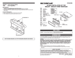
FORD Crown Victoria 1995-09 / Econline 1997-08 / Escape 2001-05
Explorer 1995-01 / F-250 1999-04 / F-350 1999-04 / F-550 1999-04
Ranger 1995-09 / Windstar 1999-03 / LINCOLN Continental 1995-97
Mark 8 1996-98 / Towncar 1995-02 / MAZDA B-Series Pickup 1995-09
MERCURY Grand Marquis 1995-09 / Mountaineer 1997-01
Mariner 2005-07 / Marauder 2003-04
1
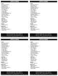
ALL VEHICLES
3
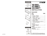
Fig. A
"A"
2
"A"
"A"
"B"
Cut and remove the Mounting Bracket
("A") and the bottom mounting legs
("B") from the Radio Housing. Skip to
the Installation Intructions for ALL
VEHICLES on Page #2.
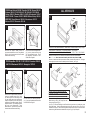
Disconnect the negative battery terminal to
prevent an accidental short circuit. Using Metra's
86-5618, pull the factory head unit from the dash
and disconnect the wiring.
FORD Expedition 1997-00 / F-150 1997-00 / Excursion 2000-05
LINCOLN Blackwood 2001-03 / Navagator 1997-02
1
2
CROWN VICTORIA, GRAND MARQUIS, MARAUDER, TOWNCAR, MARK 8: Skip to step #5.
CONTINENTAL, ECONOLINE, F-150, MOUNTAINEER: Skip to step #4.
B-SERIES PICKUP, EXPEDITION, EXPLORER, F-150, F-250, F-350, F-550, ESCAPE,
RANGER, WINDSTAR, EXCURSION, BLACKWOOD, NAVIGATOR, MARINER
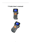
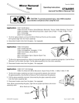
Metra recommends installing the kit with the pocket at the top.
However, to install the kit with the pocket at the bottom, locate the slots on tabs "A". Using the
slots as a guide, cut and remove the shaded portions of the tabs. (see Fig. A)
4
Fig. A
Fig. B
"A"
Disconnect the negative battery terminal to
prevent an accidental short circuit. Place
your index fingers on the inner edges of the
a/c vents (shown above) and push inward.
Grasp the exposed lip of each vent opening
and pull out on the radio trim bezel. Remove
the dash trim bezel. (The airbag wiring does
Using
NOT need to be disconnected).
Metra's 86-5618, pull the factory head unit
from the dash and disconnect the wiring.
1
B-SERIES PICKUP, ECONOLINE, EXPEDITION,
EXPLORER, EXCURSION, F-150, F-250, F-350, F-550,
ESCAPE, RANGER, WINDSTAR, CONTINENTAL,
BLACKWOOD, NAVAGATOR, MARINER, MOUNTAINEER
Cut and remove the Mounting Bracket
("A"). Skip to the Installation Instructions for
ALL VEHICLES on Page #2.
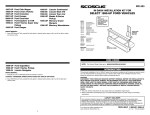
Fig. C
Secure the Mounting Bracket to the back of the
Radio Housing with (2) 3/8" Phillips Pan-head
Screws supplied. (see Fig. A)
(see Fig. A). Slide the DIN cage into the Radio Housing and secure by bending the metal
locking tabs down. Slide the aftermarket head unit into the cage until secure. (see Fig. B).
Slide the Rear Support onto the Mounting Bracket and mount the Support to the back of the
head unit using the hardware included with the unit. (see Fig. C). Skip to step #6.
2