1
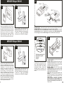
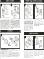
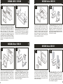
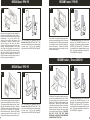
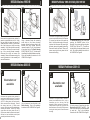
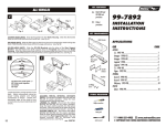
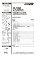
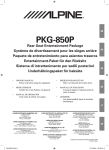
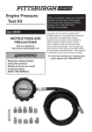
Rev.021304
KIT FEATURES
ISO and DIN
unit provisions
Pocket (holds 2
jewel cases)
KIT COMPONENTS
Radio Housing
99-7417
AT-710NI
AW-710NI
INSTALLATION
INSTRUCTIONS
APPLICATIONS
PAGE
CAR
(4) #8 x1/2”" Phillips
Pan-head Screws
ISO Trimring
Bracket Set #1
Bracket
Set #2
ISO
Brackets
Bracket Set #3
TOOLS REQUIRED
Phillips screwdriver
Cutting tool
INFINITI
I-30 1996-99....................................................................... 9
MERCURY
Villager 1993-95................................................................1
Villager 1996-98................................................................1
Villager 1999-02................................................................ 2
NISSAN
200SX 1995-98.................................................................. 2
240SX 1995-98................................................................... 3
Altima 1998-01.................................................................. 3
Frontier 1998-01............................................................... 4
Frontier 2002-04............................................................... 4
Maxima 1995-99............................................................... 5
Maxima 2000-03*............................................................. 5
Pathfinder 1996-00/Infinity QX4 1997-00............... 6
Pathfinder 2001-03.......................................................... 6
Quest 1993-95................................................................... 7
Quest 1996-98................................................................... 7
Quest 1999-02................................................................... 2
Sentra 1995-99.................................................................. 8
Xterra 2000-01................................................................... 8
Xterra 2002-04.................................................................... 4
* Fits all models EXCEPT the Bose and Comfort & Convenience pkgs .
KNOWLEDGE IS POWER
Enhance your installation and fabrication skills
by enrolling in the most recognized and respected
mobile electronics school in our industry.
Log onto www.installerinstitute.com
or call 800-354-6782 for more information
and take steps toward a better tomorrow.
1-800-221-0932
Socket wrench
www.metraonline.com
© COPYRIGHT 2001-2009 METRA ELECTRONICS CORP.
1
4
MERCURY Villager 1993-95
Fig. A
2
1
Fig. B
"D"
PATENT
PENDING
"D"
"D"
Disconnect the negative battery terminal to
prevent an accidental short circuit. Remove
(1) screw above the climate controls. Unclip
the radio trim bezel and remove. Remove
(4) Phillips screws securing the factory radio
housing and remove the housing.
Disconnect the wiring. Remove (8) Phillips
screws securing the factory radio to the
factory radio housing and remove the radio.
PATENT
PENDING
"D"
Cut and remove all mounting tabs on
Bracket Set #2 EXCEPT tabs "D". (The
tabs can be identified by the stamped letter
by each tab). Skip to the Installation
Instructions for ALL VEHICLES on Page #9.
5
MERCURY Villager 1996-98
1
DIN HEAD UNITS: Slide the DIN cage into the kit and secure by bending the metal locking
tabs down. Slide the aftermarket head unit into the cage until secure (see Fig. A).
ISO HEAD UNITS: Secure the ISO Brackets to the sides of the aftermarket head unit with the
screws supplied with the unit. Slide the head unit assembly into the Radio Housing until the
side clips engage and attach the ISO Trimring over the mounted head unit (see Fig. B).
A
B
C
2
D
Fig. A
"D"
"D"
"D"
Disconnect the negative battery terminal to
prevent an accidental short circuit. Remove
(4) plastic screws from the base of the storage
compartment. Pop out (4) anchor clips
(securing the screws) and remove the
compartment. Remove (2) Phillips screws
from the base of the radio trim bezel.
Remove (2) Phillips screws above the radio
opening. Remove the ashtray. Pull up and
out on the radio trim bezel and remove the
bezel. Remove (4) Phillips screws securing
the factory radio housing and remove the
housing. Disconnect the wiring. Remove (2)
Phillips screws securing the factory radio to
the housing and remove the radio.
6
"D"
Cut and remove all mounting tabs on
Bracket Set #2 EXCEPT tabs "D". (The
tabs can be identified by the stamped letter
by each tab). Skip to the Installation
Instructions for ALL VEHICLES on Page #9.
A) Strip wire ends back 1/2"
B) Twist ends together
C) Solder
D) Tape
Locate the factory wiring harness in the
dash. Metra recommends using the
proper mating adaptor and making
connections as shown. (Isolate and
individually tape off the ends of any
unused wires to prevent electrical short
circuit).
Re-connect the battery terminal and test the unit
for proper operation.
MAXIMA 1995-99, I-30: Mount the head unit/kit
assembly to the trim bezel and factory bracket
assembly with factory screws and mount to the
sub-dash with factory screws (Fig. A).
MAXIMA 2000-02: Mount the head unit/kit
assembly to the factory bracket assembly with (4)
Phillips Flat-head Screws supplied and mount
to the sub-dash with factory screws.
240SX: Mount the head unit/kit assembly to the
trim bezel (using tabs "B") with factory screws
and then to the sub-dash (using tabs "C") with
factory screws.
200SX, ALTIMA, FRONTIER, PATHFINDER,
QUEST, SENTRA, VILLAGER, XTERRA: Mount
the head unit/kit assembly to the sub-dash with
factory screws.
10
INFINITI I-30 1996-99
1
2
MERCURY Villager / NISSAN Quest 1999-02
2
1
Fig. A
"A"
"A"
"A"
Fig. B
"A"
"A"
Disconnect the negative battery terminal to
prevent an accidental short circuit. Unclip the
gear shifter trim bezel and remove (2) screws
exposed. Remove (1) screw to the left of the
ashtray and unclip the ashtray assembly.
Unclip the clock/vent assembly and remove.
Remove (4) screws from the top of the
mounting bracket assembly. Disconnect the
wiring and remove the assembly. Remove
the screws securing the mounting brackets to
to the assembly and remove the brackets.
Using a hammer, flatten the protruding screw
holes on the factory mounting brackets.
Mount the factory pocket to the brackets with
those screws previously removed in step #1
(Fig. A). Cut and remove all mounting tabs on
the Radio Housing EXCEPT tabs "A" (Fig.
B). The tabs can be indentified by the
stamped letter on each tab. Skip to the
Installation Instructions for ALL VEHICLES
on Page #9.
ALL VEHICLES
Disconnect the negative battery terminal to
prevent an accidental short circuit. Open
the ashtray/cupholder assembly, depress
the retaining clips on each side and remove
the assembly. Remove (2) Phillips screws
from each side of the ashtray/cupholder
assembly. Remove (4) plastic rivets from
the lower pocket and slide the pocket back.
(NOTE: It is NOT necessary to remove the
pocket. Unclip the dash trim bezel and
remove.
Remove (4) Phillips screws
securing the factory head unit and
disconnect the wiring.
Cut Bracket Set #1 along the scored lines
removing the SHADED portions of the
Brackets. Cut and remove all mounting tabs
EXCEPT tabs "A". (The tabs can be
identified by the stamped letter by each tab).
Skip to the Installation Instructions for ALL
VEHICLES on Page #9.
NISSAN 200SX 1995-98
3
1
2
"A"
"A"
Fig. B
"A"
Fig. A
"A"
"A"
240SX, I-30, MAXIMA: Skip to step #4.
ALTIMA, FRONTIER, PATHFINDER, QUEST, VILLAGER, XTERRA: Cut and remove the
mounting tabs from the Radio Housing and mount the converted Brackets to the Housing with
(4) #8 x Ω" Phillips Flat-head Screws supplied (Fig. A).
200SX, SENTRA: Cut and remove the mounting tabs from the Radio Housing. Mount one of
the converted Brackets to the Housing with (2) #8 x 1/2" Phillips Flat-head Screwssupplied
and mount one side of the cupholder to the Bracket with (1) factory screw and (1) locating pin.
Mount the other Bracket to the Housing with (2) #8 x 1/2" Phillips Flat-head Screwssupplied
and mount the other side of the cupholder with (1) factory screw and (1) locating pin (Fig. B).
9
Disconnect the negative battery terminal to
prevent an accidental short circuit. Unclip
the dummy plate from the center of the
switch panel (above the radio opening).
Unclip the radio trim bezel and remove.
Remove (4) Phillips screws securing the
factory head unit and disconnect the wiring.
Remove (2) Phillips screws securing the
factory cupholder and remove.
"A"
Cut Bracket Set #3 along the scored lines
removing the SHADED portions of the
Brackets. Cut and remove all mounting tabs
EXCEPT tabs "A". (The tabs can be
identified by the stamped letter by each tab).
Skip to the Installation Instructions for ALL
VEHICLES on Page #9.
2
3
NISSAN 240SX 1995-98
1
2
NISSAN Sentra 1995-99
2
1
"C"
"A"
"C"
"B"
"A"
"A"
"A"
"A"
"B"
Disconnect the negative battery terminal to
prevent an accidental short circuit. Unclip the
climate control trim bezel and remove (2)
screws exposed. Unclip the gear shifter trim
bezel and remove (2) screws exposed.
Remove the ashtray and (1) screw exposed.
Unclip the radio trim bezel (the factory head
unit, pocket and mounting brackets are
secured to the bezel). Disconnect the wiring.
Remove the screws securing the mounting
brackets to the assembly and remove the
brackets.
Cut and remove all mounting tabs on the
Radio Housing EXCEPT tabs "B" and "C".
(The tabs can be identified by the stamped
letter on each tab). Skip to the Installation
Instructions for ALL VEHICLES on Page #9.
Disconnect the negative battery terminal to
prevent an accidental short circuit. Unclip
the dummy plate from the center of the
switch panel (above the radio opening).
Unclip the radio trim bezel and remove.
Remove (4) Phillips screws securing the
factory head unit and disconnect the wiring.
Remove (2) Phillips screws securing the
factory cupholder and remove.
NISSAN Altima 1998-01
1
2
"A"
Cut Bracket Set #3 along the scored lines
removing the SHADED portions of the
Brackets. Cut and remove all mounting tabs
EXCEPT tabs "A". (The tabs can be
identified by the stamped letter by each tab).
Skip to the Installation Instructions for ALL
VEHICLES on Page #9.
NISSAN Xterra 2000-01
"B"
1
2
"B"
"B"
"B"
"A"
"B"
"B"
"A"
Disconnect the negative battery terminal to
prevent an accidental short circuit. Unclip
the gear shifter trim bezel and remove (2)
Phillips screws exposed.
Remove (2)
Phillips screws above the radio opening.
Unclip the radio trim bezel. Remove (4)
Phillips screws from the factory head unit
and disconnect the wiring.
Cut Bracket Set #3 along the scored lines
removing the SHADED portions of the
Brackets. Cut and remove all mounting tabs
EXCEPT tabs "B". (The tabs can be
identified by the stamped letter by each tab).
Skip to the Installation Instructions for ALL
VEHICLES on Page #9.
Disconnect the negative battery terminal to
prevent an accidental short circuit. Remove
the ashtray and (2) Phillips screws exposed
in the ashtray cavity. Unclip the radio trim
bezel and remove. Remove (4) Phillips
screws securing the factory head unit and
disconnect the wiring.
Cut Bracket Set #2 along the scored lines
removing the SHADED portions of the
Brackets. Cut and remove all mounting tabs
EXCEPT tabs "A" and "B". (The tabs can
be identified by the stamped letter by each
tab). Skip to the Installation Instructions for
ALL VEHICLES on Page #9.
8
7
NISSAN Quest 1996-98
NISSAN Frontier 1998-01
2
1
2
1
"D"
"B"
"D"
"A"
"D"
"B"
Disconnect the negative battery terminal to
prevent an accidental short circuit. Remove
(4) plastic screws from the base of the storage
compartment. Pop out (4) anchor clips
(securing the screws) and remove the
compartment. Remove (2) Phillips screws
from the base of the radio trim bezel.
Remove (2) Phillips screws above the radio
opening. Remove the ashtray. Pull up and
out on the radio trim bezel and remove the
bezel. Remove (4) Phillips screws securing
the factory radio housing and remove the
housing. Disconnect the wiring. Remove (2)
Phillips screws securing the factory radio to
the housing and remove the radio.
"A"
"D"
Cut and remove all mounting tabs on
Bracket Set #2 EXCEPT tabs "D". (The
tabs can be identified by the stamped letter
by each tab). Skip to the Installation
Instructions for ALL VEHICLES on Page #9.
Disconnect the negative battery terminal to
prevent an accidental short circuit. Remove
the ashtray and (2) Phillips screws exposed
in the ashtray cavity. Unclip the radio trim
bezel and remove. Remove (4) Phillips
screws securing the factory head unit and
disconnect the wiring.
Cut Bracket Set #2 along the scored lines
removing the SHADED portions of the
Brackets. Cut and remove all mounting tabs
EXCEPT tabs "A" and "B". (The tabs can
be identified by the stamped letter by each
tab). Skip to the Installation Instructions for
ALL VEHICLES on Page #9.
NISSAN Frontier / Xterra 2002-04
NISSAN Quest 1993-95
1
1
2
2
"B"
"D"
"A"
"D"
"B"
"D"
"A"
Disconnect the negative battery terminal to
prevent an accidental short circuit. Remove
(1) screw above the climate controls. Unclip
the radio trim bezel and remove. Remove
(4) Phillips screws securing the factory radio
housing and remove the housing.
Disconnect the wiring. Remove (8) Phillips
screws securing the factory radio to the
factory radio housing and remove the radio.
"D"
Cut and remove all mounting tabs on
Bracket Set #2 EXCEPT tabs "D". (The
tabs can be identified by the stamped letter
by each tab). Skip to the Installation
Instructions for ALL VEHICLES on Page #9.
Disconnect the negative battery terminal to
prevent an accidental short circuit. Unclip
the gear shifter trim bezel and remove.
Remove (2) Phillips screws exposed in the
shifter cavity. Remove (2) Phillips screws
under the climate control cluster. Unclip the
radio trim bezel and remove. Remove (4)
Phillips screws securing the factory head
unit and disconnect the wiring. CAUTION:
DO NOT CYCLE THE KEY WHEN
REMOVING A DASH WITH PASSENGER
AIRBAG ON/OFF SWITCH).
Cut Bracket Set #2 along the scored lines
removing the SHADED portions of the
Brackets. Cut and remove all mounting tabs
EXCEPT tabs "A" and "B". (The tabs can
be identified by the stamped letter by each
tab). Skip to the Installation Instructions for
ALL VEHICLES on Page #9.
4
NISSAN Maxima 1995-99
1
2
NISSAN Pathfinder 1996-00 /Infinity QX4 1997-00
1
Fig. A
2
"C"
"A"
"A"
"A"
"C"
"A"
Fig. B
"A"
Disconnect the negative battery terminal to
prevent an accidental short circuit. Unclip
the gear shifter trim bezel and remove (2)
screws exposed. Remove (1) screw to the
left of the ashtray and unclip the ashtray
assembly. Unclip the clock/vent assembly
and remove. Remove (4) screws from the
top of the mounting bracket assembly.
Disconnect the wiring and remove the
assembly. Remove the screws securing the
mounting brackets to to the assembly and
remove the brackets.
Using a hammer, flatten the protruding
screw holes on the factory mounting
brackets. Mount the factory pocket to the
brackets with those screws previously
removed in step #1 (Fig. A). Cut and remove
all mounting tabs on the Radio Housing
EXCEPT tabs "A" (Fig. B). The tabs can be
indentified by the stamped letter on each tab.
Skip to the Installation Instructions for ALL
VEHICLES on Page #9.
Disconnect the negative battery terminal to
prevent an accidental short circuit. Remove
(2) screws from the base of the radio trim
bezel. Unclip the bottom edge of the radio
trim bezel and disconnect the hazard light,
defroster, wiper and cligarette lighter wiring.
Remove the radio trim bezel. Remove (4)
screws securing the factory head unit and
disconnect the wiring.
NISSAN Maxima 2000-03
1
2
5
Cut Bracket Set #2 along the scored lines
removing the SHADED portions of the
Brackets. Cut and remove all mounting tabs
EXCEPT tabs "A" and "C". (The tabs can
be identified by the stamped letter by each
tab). Skip to the Installation Instructions for
ALL VEHICLES on Page #9.
NISSAN Pathfinder 2001-03
2
1
"B"
Illustration not
available
Disconnect the negative battery terminal to
prevent an accidental short circuit. Unclip the
vent/radio trim bezel assembly and remove.
(NOTE: For Bose systems, the vent assembly
will be removed without the bezel). Remove
the ashtray insert and (1) Phillips screw
exposed. Unclip the gear shifter bezel/ashtray
assembly and remove. Remove (2) Phillips
screws above the factory head unit and (2)
Phillips screws below the climate control panel.
Remove the head unit/climate control panel
assembly and disconnect the wiring.
"A"
Illustration not
available
"B"
"B"
"B"
Cut and remove all mounting tabs on the
Radio Housing. Skip to the Installation
Instructions for ALL VEHICLES on Page #9.
Disconnect the negative battery terminal to
prevent an accidental short circuit. Using a
screwdriver, pry out on the top of the vent
assembly (w/ clock) and remove. Remove (2)
Phillips screws from the top of the radio trim
bezel and remove. Remove (4) Phillips screws
securing the factory head unit and disconnect
the wiring.
Cut and remove all mounting tabs from
Bracket Set #1 EXCEPT tabs "B". (The
tabs can be identified by the stamped letter
by each tab). Skip to the Installation
Instructions for ALL VEHICLES on Page #9.
6