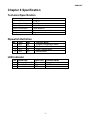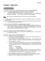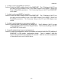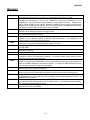
1
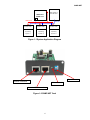
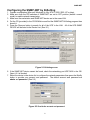
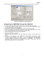
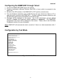
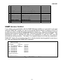
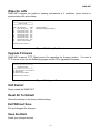
SNMP-NET
UPS SNMP Card
(Web-Based monitoring SNMP Card)
User’s Manual
PN: 34000281 R1
SNMP-NET
Table of Contents
Chapter 1 Introduction ....................................................................................................3
Features...............................................................................................................................3
System Application ..............................................................................................................3
Chapter 2 Installation ......................................................................................................4
Chapter 3 Configuration..................................................................................................5
Configuring the SNMP-NET by EzSetting ...........................................................................5
Configuring the SNMP-NET through COM Port ..................................................................6
Configuring the SNMP-NET through Telnet.........................................................................7
Configuration by Text Mode .................................................................................................7
User Manager ......................................................................................................................8
System Configuration ..........................................................................................................8
SNMP Access Control .........................................................................................................9
SNMP Trap ..........................................................................................................................10
Time Server .........................................................................................................................10
Wake On LAN ......................................................................................................................11
Upgrade Firmware ...............................................................................................................11
Soft Restart ..........................................................................................................................11
Reset All to Default ..............................................................................................................11
Exit without Save .................................................................................................................11
Save and Exit.......................................................................................................................11
Chapter 4 Managing SNMP-NET.....................................................................................12
Running the Web Browser (Internet Explorer).....................................................................12
Smart Shutdown ..................................................................................................................12
External Battery Pack ..........................................................................................................12
UPS Shutdown Schedule ....................................................................................................12
UPS Shutdown during Power Crisis ....................................................................................13
Wake Computer Up .............................................................................................................13
Email Notification .................................................................................................................13
SNMP Access Control Setting .............................................................................................14
Power Fail/Restore Simulation ............................................................................................14
Updating SNMP-NET Firmware from Windows...................................................................14
Chapter 5 Shutdown Software........................................................................................15
Installation Of SNMP-NET Client in Windows .....................................................................15
Installation of SNMP Shutdown Agent in Windows .............................................................15
Chapter 6 Specification...................................................................................................16
Technical Specification ........................................................................................................16
Dipswitch Definition .............................................................................................................16
LED Indicator .......................................................................................................................16
Chapter 7 Appendix .........................................................................................................17
Troubleshooting ...................................................................................................................17
Glossary...............................................................................................................................19
Obtaining Technical Assistance ...........................................................................................20
Limited Product Warranty ....................................................................................................21
2
SNMP-NET
Chapter 1 Introduction
Features
• Network connection through RJ45 connector
Allows connection of the UPS directly to the Ethernet network through a RJ45 connector without
using RS232 ports on the computer and without loading any individual UPS management
software on the network server.
• Network UPS management
Allows remote management of the UPS from any workstation through Internet or Intranet.
• Remote UPS monitoring via SNMP, HTTP
Allows monitoring of the UPS using the MIB (Management Information Base), or an Internet
Browser.
• Configure UPS and system functions from any client (password protected)
Configure the UPS and the system parameters from any SNMP management station or through
an Internet Browsers using HTTP forms and objects.
• Event logs & Metering data stored in the EEPROM
Provides historical data of UPS’ power events, power quality, current status and battery
condition.
• Multiple server shutdown
The shutdown software included provides an automatic shutdown either pre-programmed by
administrator or when critical power events occur.
• Notification of users via SNMP Traps and e-mail through SMTP
• Network Time Protocol supported
• Telnet support for configuration
• BOOTP/DHCP supported
• NetBIOS Name Service supported
• MD5 HTTP security
System Application
SNMP-NET is an interface between the UPS and the network. It can obtain the status from a
UPS and issue commands to it. SNMP-NET supports two kinds of protocol – SNMP and HTTP
for user access. Through the SNMP NMS and Web Browser, the user can obtain the UPS
status; issue commands to UPS and set-up the SNMP-NET through the network.
SNMP-NET also provides shutdown software for various OS’. The shutdown software that
runs under various OS can link to the SNMP-NET automatically through the network and
communicate with SNMP-NET via SNMP protocol. The shutdown software retrieves UPS
information from SNMP-NET. The Shutdown software will then proceed to the shutdown
process in order to prevent the abnormal shutoff of host or server due to power events.
3
SNMP-NET
UPS
NMS Station or
W eb Browser
SNMP-NET
SNMP Card
Power Line
Shutdown S/W
Operating
System 1
Ethernet
Shutdown S/W
Shutdown S/W
Operating
System 2
Operating
System N.
Figure 1-1 System Application Diagram
Dip Switches
Ethernet Connection
Reset Button
Console / ENV Connection
Figure 1-2 SNMP-NET Card
4
SNMP-NET
Chapter 2 Installation
Note: The SNMP-NET cards are designed to be Hot Swappable, but there is a remote chance
that when Hot-Swapping the SNMP-NET card that the UPS will shutdown. MINUTEMAN
recommends following steps 1 through 8 when installing the SNMP-NET card, but to hot-swap,
skip to step number 3 and omit steps 6, 7.
1.
2.
3.
4.
5.
6.
Turn off all the equipment that is plugged into the UPS.
Turn off the UPS and unplug the UPS’s power cord from the AC wall outlet.
Remove the Option Slot cover plate from the rear panel of the UPS.
Insert the SNMP-NET in to the option slot and secure with the retaining screws.
Connect the SNMP-NET device to your LAN.
Open the Internet browser and link to the SNMP-NET device by typing the default host name
“SNMP-NET” in the address box.
7. Login as administrator with “admin” for the user and “password” for the default password.
8. Open the “User Manager” page to manage your accounts and passwords.
9. Switch to the “System Configuration” page and change the default Host Name.
10. Configure the IP address, Subnet Mask, Gateway IP for SNMP-NET device. If there is no
DNS server then you need to assign an IP address for the mail server if you want to be
notified e-mail.
11. We recommended disabling the BOOTP/DHCP option and assign a valid static IP address.
12. Open the “Time Server” page to synchronize the SNMP-NET device and the Time Server.
Please refer to next section on how to construct your SNTP server.
Note: If you do not have a BOOTP/DHCP server in your LAN then follow below:
13. Make sure both of the SNMP-NET device and your workstation are in the same LAN.
14. Open EzSetting from the CD, and refer to next chapter for configuring SNMP-NET by
EzSetting.
15. Change the Host Name, and the IP Address.
16. Disable the BOOTP/DHCP option in the System Configuration group.
17. Please refer to next Chapter “Configuring the SNMP-NET by EzSetting” section for more
detail information on configuring the SNMP-NET.
Chapter 3 Configuration
The easiest way to configure the SNMP-NET is by running the EzSetting program. You can
find the program on the CD. Please see the sub-section below for more information.
If you have configured the essential network parameters successfully, you can launch the
Internet browser or telnet to the device. The first thing is to open the User Manager page and
change your account and password.
5
SNMP-NET
Configuring the SNMP-NET by EzSetting
1. Prepare a workstation (Microsoft Windows 9x, Me, NT4.0, 2000, 2003, XP or later).
2. Make sure both the DIP-switches of SNMP-NET are set to OFF position (default: normal
mode) to enable network transmission.
3. Make sure the workstation and SNMP-NET device are in the same LAN.
4. Put the CD (provided) in the CD-ROM drive and find the SNMP-NET EzSetting program then
launch it.
5. Press the Discover button to search for all of the UPS’ in the LAN. All of the UPS SNMP
DEVICE will be listed in the Device List. (See 2-1)
Figure 2-1 EzSetting screen.
6. If the SNMP-NET device cannot be found, check the networking port UDP 3456 in the OS.
Open it if it is blocked.
7. Select the device in the device list to configure the network parameters then press the Modify
button to provide your account and password. The default account and password are
admin and password. (See 2-2)
Figure 2-2 Provide the account and password.
6
SNMP-NET
8. Click on the Configuration button and setup the essential network parameters. (See 2-3)
Figure 2-3 Configure the system parameters.
Configuring the SNMP-NET through the COM Port
1. Prepare a workstation (Microsoft Windows 9x, Me, NT4.0, 2000, 2003, XP or later).
2. Use the RJ45 to DB9 serial cable (provided) to connect between the SNMP-NET Console
port and the COM port on the workstation.
3. Set both the DIP-switches of the SNMP-NET to OFF position (normal mode).
4. From the workstation running Microsoft Windows (9x, Me, NT4.0, 2000, 2003, XP or later),
click on the HyperTerminal icon of the accessory programs group.
5. Enter a name and choose an icon for the connection.
6. Select direct COM port connection.
7. Setup the COM port parameters - 2400 bps, 8 data bits, no parity, 1 stop bit and no flow
control.
8. Set both the DIP-switches of the SNMP-NET to ON position (configuration mode).
Messages will be displayed on the screen. Key in the administrator account (default
account is admin) and password (default password is password). The SNMP-NET
configuration utility main menu will be displayed on the screen. Please refer to the Text
Mode Configuration section for more information.
7
SNMP-NET
Configuring the SNMP-NET through Telnet
1. Connect the SNMP-NET SNMP card to the network.
2. Prepare a workstation (Microsoft Window, Max OSX or Linux), which is connected to the
same LAN.
3. Set both of the DIP-switches of the SNMP-NET to OFF position (normal mode).
4. From the Windows workstation open a DOS Prompt and type “telnet Host Name or IP” to
open the telnet connection with SNMP-NET. For other operating systems, please run the
OS shell and type the same command as in the DOS prompt.
5. Messages will be displayed on the screen. Key in the administrator account (default
account is admin) and password (default password is password). The SNMP-NET
configuration main menu will be displayed on the screen. Please refer to the Text Mode
Configuration section for more information.
Note: SNMP-NET will terminate the telnet connection if there is no data transmission after 1
minute.
Configuration by Text Mode
+========================+
UPS Web Card Main Menu
+========================+
UPS Web Version 1.0
[1]. User Manager
[2]. System Configuration
[3]. SNMP Access Control
[4]. SNMP Trap
[5]. Time Server
[6]. Mail Server
[7]. Wake On LAN
[8]. Upgrade Firmware
[9]. Soft Restart
[a]. Reset All To Default
[b]. Reset Hub To Default
[z]. Exit Without Save
[0]. Save And Exit
Please Enter Your Choice =>1
Figure 2-4 SNMP-NET Main Menu.
8
SNMP-NET
User Manager
+========================+
User Manager
+========================+
Administrator
[1]. Account:
admin
[2]. Password:
********
[3]. Limitation: Only in This LAN
Device Manager
[4]. Account:
device
[5]. Password:
********
[6]. Limitation: Only in This LAN
Read Only User
[7]. Account:
user
[8]. Password:
********
[9]. Limitation: Only in This LAN
[0]. Back To Previous Menu
Please Enter Your Choice =>
Figure 2-5 SNMP-NET User Manager Menu
No. Function
1.
2.
3.
4.
5.
6.
Description
Default
Administrator Account Administrator gets the whole rights to modify “admin”
Administrator Password the SNMP-NET and UPS settings.
“password”
Device
Manager
is
permitted
to
change
the
Device Account
“device”
network setting but has the ability to configure
Device Password
“password”
the UPS settings.
User Account
“user”
Read Only User can observe the UPS
information only.
User Password
“password”
System Configuration
+========================+
| System Configuration
|
+========================+
[1]. IP Address:
[2]. Subnet Mask:
[3]. Gateway IP:
[4]. DNS IP:
[5]. BOOTP/DHCP Client:
[6]. HTTP Server:
[7]. Telnet Server:
[8]. HTTP Server Port:
[9]. Telnet Server Port:
[a]. Host Name (NetBIOS):
[b]. System Contactor:
[c]. System Location:
[0]. Back To Previous Menu
192.168.001.100
255.255.255.000
192.168.001.254
192.168.001.001
Enable
Enable
Enable
80
23
SNMP-NET
Please Enter Your Choice =>
Figure 2-6 System Configuration Menu
9
SNMP-NET
No. Function
1.
2.
3.
4.
5.
6.
7.
8.
9.
a.
b.
c.
Description
Default
IP Address
The SNMP-NET IP address.
Subnet Mask
The sub-net mask setting.
Gateway IP
The network default gateway.
DNS IP
Domain Name Server IP address
BOOTP/DHCP Client Enable/Disable BOOTP/DHCP protocol
HTTP Server
Enable/Disable HTTP protocol
Telnet Server
Enable/Disable telnet protocol
HTTP Server Port
HTTP networking port
Telnet Server Port
Telnet networking port
Host Name (NetBIOS) Host name for Windows
System Contactor
Alphanumeric string
System Location
Alphanumeric string
192.168.001.100
255.255.255.000
192.168.001.254
192.168.001.001
Enable
Enable
Enable
80
23
SNMP-NET
SNMP Access Control
If you wish to use a workstation with the SNMP Manager installed, or if you wish to set more
restrictive SNMP-NET access, you can use the access table to add the IP address of the PC’s
on which you wish to modify the access permissions (Figure 2-7). The communication protocol
between the shutdown software (SNMP-NET Client) and the SNMP-NET device is SNMP. The
administrator needs to maintain this table for all workstations to keep the UPS and the
workstations working correctly. The index 01 is a special design for all read only workstations.
SNMP-NET checks the community string first to identify that the incoming packet is read only or
not, if they are identical then SNMP-NET responses.
+========================+
|
SNMP Access Table
|
+========================+
Index NMS IP
Community
[1] 01 Other SNMP NMSs public
[2] 02 172.016.176.141
SNMP-NET
[3] 03 000.000.000.000
[4] 04 000.000.000.000
[5] 05 000.000.000.000
[6] 06 000.000.000.000
[7] 07 000.000.000.000
[8] 08 000.000.000.000
[0]. Back To Previous Menn
Permission
Read Only
Read/Write
Not Access
Not Access
Not Access
Not Access
Not Access
Not Access
Please Enter Your Choice =>
Figure 2-7 SNMP Access Table.
10
SNMP-NET
SNMP Trap
If you want to use a PC and perform the SNMP manager ‘trap’ function in order to manage the
UPS through SNMP-NET, the IP address of the PC must be added to the SNMP Trap list. The
Event Level field is used to decide what kind of power events should be sent to the target
address. There are 3 levels of power events: Information, Warning and Severity. If you select
the Information then all of the power events will be send to the target IP address, warning level
will send the Warning and Severity events to the target address.
+========================+
|
SNMP Trap
|
+========================+
Index Target IP
Community
[1]
172.016.176.142 SNMP-NET
[2]
172.016.176.143 private
[3]
172.016.176.144 public
[4]
000.000.000.000
[5]
000.000.000.000
[6]
000.000.000.000
[7]
000.000.000.000
[8]
000.000.000.000
[0].Back To Previous Menu
Event Level
Information
Warning
Severity
None
None
None
None
None
Please Enter Your Choice =>
Figure 2-8 SNMP Trap.
Time Server
There are 2 ways to provide the current time and the date to SNMP-NET; one way is to set the
system time manually. The other way is to setup a Time Server for SNMP-NET, SNMP-NET
supports SNTP. If you have installed the SNMP-NET Client from the bundled CD, you can just
assign the host in the Time Server IP address, because SNMP-NET Client has the ability to act
as a Time Server for SNMP-NET device. Instead of using the SNMP-NET Client as a Time
Server, install the Simple TCP/IP Services from Add/Remove Windows Components.
+========================+
|
Time Server
|
+========================+
[1].Time Selection:
SNTP
[2].Time Zone:
-8 hr
[3].1st Time Server:
172.016.176.141
[4].2nd Time Server:
jesse-tri
[5].Manual Date:
01/01/2000 (MM/DD/YYYY)
[6].Manual Time:
00:00:00 (hh:mm:ss)
[0].Back To Previous Menu
Please Enter Your Choice =>
Figure 2-9 Time Server.
11
SNMP-NET
Wake On LAN
SNMP-NET supports the packet to wakeup workstations in 2 conditions: power restore or
system startup with a time delay.
+========================+
|
Wake On LAN
|
+========================+
Index MAC Address
Delay
[1]
00-0c-08-34-4d-57 001
[2]
00-00-00-00-00-00 000
[3]
00-00-00-00-00-00 000
[4]
00-00-00-00-00-00 000
[5]
00-00-00-00-00-00 000
[6]
00-00-00-00-00-00 000
[7]
00-00-00-00-00-00 000
[8]
00-00-00-00-00-00 000
[0]
Back To Previous Menu
Trigger Conditions
(Power Restore)(System Startup)
Please Enter Your Choice =>
Figure 2-10 Setting Trap Receivers.
Upgrade Firmware
SNMP-NET supports TFTP Client protocol for upgrading the firmware version. You need a
TFTP server or just run the EzSetting program on the CD to upgrade the firmware.
+========================+
|
Upgrade Firmware
|
+========================+
[1]. TFTP Server IP: 172.016.176.141
[2]. Upgrade Now
[0]. Back To Previous Menu
Please Enter Your Choice =>
Figure 2-11 Upgrade Firmware.
Soft Restart
Simply restart the SNMP-NET.
Reset All To Default
Resets the settings to the factory default settings.
Exit Without Save
Exit and disregard the changes.
Save And Exit
Saves your changes and exit.
12
SNMP-NET
Chapter 4 Managing SNMP-NET
Running the Web Browser (Internet Explorer)
1. Make sure that you have a TCP/IP network already installed.
2. If there is no DHCP network service on the network, contact your network administrator to
get an IP address for you workstation that has the same network’s address as the
SNMP-NET IP address. The default IP address of SNMP-NET is 192.168.1.100.
3. Start your Web Browser. Enter the URL “http://host_name” or “http://ip_address” in the
address box. The SNMP-NET will then ask for your account and password, input the
correct account and password then the UPS management home page will be shown on the
screen.
Note: SNMP-NET will logout the user automatically if there is no data transmission through
HTTP connection for more than 30 minutes.
Smart Shutdown
Initiates a signal for the server to shutdown. After the user-defined “Estimated OS Shutdown
Delay”, the output power is switched off. SNMP-NET Client or SNMP ShutdownAgent must be
used on the server for it to be properly shutdown. The “Estimated OS Shutdown Delay”
includes the assigned countdown delay in the shutdown software plus the duration of OS
shutdown process. When shutdown software receives the Smart Shutdown signal, the low
battery reaction settings will be used to process the shutdown procedure.
External Battery Pack
If you are using an External Battery Pack with this UPS, the UPS must be configured so that; the
UPS will report the correct estimated runtime and the Battery capacity bar graph LEDs will
display properly. External Battery Pack is located in the Configure folder.
UPS Shutdown Schedule
UPS only:
SNMP-NET device supports two kinds of shutdown schedules – (1) Weekly Schedule, (2)
Special Day Schedule. Set both of these options to plan your UPS schedule shutdown and
restart time.
UPS + Shutdown Software (SNMP-NET Client):
If your SNMP-NET device needs to work with the shutdown software to protect your servers,
which are powered by the UPS and you want to control the schedule shutdown and restart from
SNMP-NET device then go to the Configure page and enable the “Perform Smart Shutdown in
Schedule” option. You can also set the shutdown schedule using the shutdown software. And
because the shutdown software will send the control command to UPS through SNMP to
shutdown the UPS, we have to add the server IP address with write permission in the SNMP
Table of SNMP-NET device.
Note: Before managing the UPS Shutdown Schedule, please make sure that the Date and
Time in SNMP-NET are correct.
13
SNMP-NET
UPS Shutdown during Power Crisis
UPS only:
SNMP-NET responds to two different kinds of UPS shutdown events (AC failed, Battery Low).
Go to Configure in the UPS Management menu and Login as an Administrator. Set the options
in UPS Shutdown Action section then press the Submit button.
UPS + Shutdown Software (SNMP-NET Client):
If your SNMP-NET device needs to work with the shutdown software to protect your servers,
which are powered by the UPS then you should clear all of the settings of UPS shutdown action
in the SNMP-NET device. Then set the event shutdown using the shutdown software. And
because the shutdown software will send the control command to UPS through SNMP to
shutdown the UPS, we have to add the server IP address with write permission in the SNMP
Table of SNMP-NET device.
Note: Once SNMP-NET detects there is shutdown software running the event-driven
shutdown would be cancelled.
Wake Computer Up
Check the BIOS settings and enable the WOL option. Then go to the Wake On LAN page in
the Network menu.
Note:
This feature is only available for the servers in the same LAN with SNMP-NET device.
Email Notification
This page is to setup the email notification settings to receive a notification or a report from
SNMP-NET by email.
1. SMTP Server Name or IP
This item is the Hostname of a SMTP Mail Server that will be used to send the email
messages from the SNMP-NET. If entering a Hostname, you are also required to enter the
DNS IP in the System Configuration.
2. Sender Mail Address
This item must be a legitimate email address.
3. Account
This item is the User Account of Mail Server. It is only required if Mail Server requires
authentication to send mail.
4. 1st Receiver
This item is for entering the email address of the individual you will receive the email
notification.
5. 1st Event Level
This item is for selecting the Event level of the notification that will be sent to the Mail
Receiver. The Event levels are Information, Warning and Severity.
6. 2nd Receiver
This item is for entering the email address of the individual you will receive the email
notification.
7. 2nd Event Level
This item is for selecting the Event level of the notification that will be sent to the Mail
Receiver. The Event levels are Information, Warning and Severity.
14
SNMP-NET
SNMP Access Control Setting
SNMP-NET supports SNMP protocol. You can use an NMS to manage the UPS through the
network. The IP address of the workstation must be entered in the SNMP-NET write access
table to prevent unauthorized users from configuring SNMP-NET via SNMP protocols.
Power Fail/Restore Simulation
To make sure the network configuration is correct, SNMP-NET provides two test buttons to
simulate power fail and power restore events. After pressing the test buttons, SNMP-NET will
send the related SNMP trap to the assigned target hosts and simulate the power event values to
SNMP response data. The power fail simulate will be terminated automatically in 30 minutes.
Updating SNMP-NET Firmware from Windows
To perform firmware upgrade, use the EzSetting.exe program on the CD-ROM.
1. Device List: Displays the addresses of the SNMP-NET devices present in the local
network.
2. Discover: Search for the SNMP-NET devices in the local network.
3. Add: Allows you to add the IP address of the SNMP-NET device manually.
4. Modify: Allows you to modify the parameters of the selected SNMP-NET device.
5. Remove: Removes the selected SNMP-NET device from the Device List.
6. Configuration: Provides an easy way to do the initial configuration through networking
UDP port 3456. If you cannot get the device information please check and open the UDP
port from your OS.
7. Upgrade: Allows you to upgrade the firmware for the SNMP-NET device.
15
SNMP-NET
Chapter 5 Shutdown Software
There are two kinds of shutdown software to help you to protect servers from power crisis. One
is SNMP-NET Client the other one is the SNMP-NET ShutdownAgent. Both programs have
the ability to shutdown servers gracefully.
The major difference is the SNMP-NET
ShutdownAgent can only receive SNMP traps of power fail and low battery signals but the
SNMP-NET Client can observe the UPS parameters, record power events and values.
Installation of SNMP-NET Client in Windows
1. Insert the SNMP-NET CD-ROM into the CD-ROM drive.
2. Run the “SNMP-NET Client Setup.exe” program on the CD-ROM.
3. After the set-up is complete, provide the host name or IP address of SNMP-NET device and
community string, which has been set in the SNMP Access Control menu. The SNMP-NET
Client service connects to the device automatically when the operating system initiates.
Note: When the SNMP-NET Client connects to SNMP-NET device, the schedule and UPS
Shutdown Action settings in the SNMP Card will be ignored until the connection of the
SNMP-NET Client is terminated to prevent conflicting with the settings in the SNMP-NET Client
software. In this case, you can still configure the schedule shutdown/restart and event-driven
shutdown from SNMP-NET Client software.
Installation of SNMP-NET Shutdown Agent in Windows
1. Insert the SNMP-NET CD-ROM into the CD-ROM drive.
2. Run the “SNMP-NET ShutdownAgent Setup.exe” program on the CD-ROM.
3. After the set-up is complete, provide the IP address of SNMP-NET device. The SNMP
Shutdown Agent will open the specific UDP port and listen for SNMP traps when the
operating system initiates.
16
SNMP-NET
Chapter 6 Specification
Technical Specification
Network Connection
Operating Temperature
Operating Humidity
Power Input
Power Consumption
Size
Weight
RJ-45 jack connector
0 ~ 40° C
10 ~ 80 %
9~24V DC
1 Watt Maximum
130 mm x 60 mm (L x W)
58 g
Dipswitch Definition
No.
1
2
3
4
SW1
ON
ON
OFF
OFF
SW2
ON
OFF
ON
OFF
Function Mode
Console Configuration Mode
For Environmental Sensor
Pass Through Mode
Normal Mode
LED Indicator
No.
1
2
3
Yellow LED
Flashing (0.2 sec)
Flashing (1sec)
---
Green LED
ON
ON
OFF
Function Mode
Normal operation
UPS Disconnect
Hardware or network error
17
SNMP-NET
Chapter 7 Appendix
Troubleshooting
1. How can I provide a SNTP (Simple Network Timer Protocol) server for SNMP-NET?
Solution: There are two ways to provide a network Time Server for SNMP-NET:
1) Install the SNMP-NET Client software you can find it on the CD.
2) Install the “Simple TCP/IP Services” of “Networking Services” from “Add/Remove
Windows Components”. You may need a Windows CD while installing.
Note:
Do not forget to provide the IP address of the host in the Time Server page.
2. How do I check to make sure the network connection is established between my workstation
and SNMP-NET?
Solution: Check the networking connection by typing the following command “ping HostName or
the IP address” from your workstation.
3. How to refresh the NetBIOS table in Windows operating system?
Solution: Sometimes the IP address of SNMP-NET will be changed but will keep the same host
name, although Windows will update its NetBIOS table periodically, we can force it to
purge its cache immediately by typing the following command “nbtstat -R. After that
you can connect to the SNMP-NET by its host name.
4. How can I get the IP address and MAC address from my computer?
Solution: In the Windows system, type in “ipconfig /all” at the DOS prompt.
use “ifconfig” in the shell.
For Unix system
5. Unable to ping or connect to the SNMP-NET device.
Solution: 1) Check all of the network connections.
2) Ensure that your PC and the SNMP-NET are on the same network segment (If you
do not have a router, this must be true).
3) It may be that your "arp table" contains invalid entries. You can clear the "arp
table" by rebooting, or by typing the following command at the command prompt or
Run the dialog box: arp -d
4) You can only connect to the SNMP-NET device if your PC and the SNMP-NET are
using the IP Addresses from the same address block. Normally, private LANs
use IP Addresses from one of the following blocks, which are reserved for this
purpose:
10.0.0.0 ~ 10.255.255.255
172.16.0.0 ~ 172.31.255.255
192.168.0.0 ~ 192.168.255.255
The SNMP-NET's default IP address (192.168.1.100) is from the last block. If
your LAN is using a different address block, then you will NOT be able to connect
to the SNMP-NET device via the LAN. In this case, your choices are:
• Use Terminal Mode configuration to set the SNMP-NET's IP Address.
• Use the TCP/IP arp utility to provide a (temporary) IP Address to the SNMP-NET.
• Change your PC's IP Address to allow connection via the LAN.
18
SNMP-NET
6. Unable to perform an SNMP get operation.
Solution: Check the SNMP settings stored in the SNMP-NET. The IP Address of the PC you
are using must be entered in one of the SNMP Access Control NMS IP fields, with
Read or Read/Write permission. The Community String on the PC and SNMP-NET
must match.
7. Unable to perform an SNMP set operation.
Solution: Check the SNMP settings stored in the SNMP-NET. The IP Address of the PC you
are using must be entered in one of the SNMP Access Control NMS IP fields, with
Read/Write permission. The Community String on the PC and UPS Adapter must
match.
8. Unable to receive traps at your management station.
Solution: Check the SNMP Trap settings in the SNMP-NET. The IP Address of the PC you are
using must be entered in one of the Target IP fields. The Community String on the PC
and SNMP-NET must match.
9. Forgot the administrator’s account and password.
Solution: Connect the configuration cable in the console port and set both of the DIP-switches of
SNMP-NET to ON position (configuration mode). Type in “rstadmin” while the
account and password are prompted in 30 seconds. Now the account and password
of administrator are reset to default values.
19
SNMP-NET
Glossary
Agent
Ethernet
Gateway
IP
IP Address
MAC
MIB
NMS
OID
Router
SNMP
Sub-Agent
TCP/IP
TFTP Server
UDP/IP
UPS
Implemented SNMP applications in network elements (hosts). Agents perform the network
management’s functions as requested by the network administrator from an NMS.
Local Area Network technology, can link up to 1,024 nodes in a bus network. Ethernet
provides raw data transfer in a rate of 10 megabits/sec. with actual throughputs in 2 to 3
megabits/sec. using a base-band (single-channel) communication technique. Ethernet uses
carrier sense multiple access collision detection (CSMA/CD) that prevents network failures
when two devices attempt to access the network at the same time. LAN hardware manufactures
use Ethernet protocol; their products may not be compatible.
A device that attaches to a number of networks and routes packets between them. The
packets can be different protocols at the higher levels.
Internet Protocol—The TCP/IP standard protocol defines the IP datagram as the unit of
information passed across a network.
Internet Protocol Address—A 32-bit address assigned to hosts participating in a TCP/IP
network. The IP address consists of network and host portions. It is assigned to an
interconnection of a host to a physical network.
Medium Access Control—The network layer between the physical and the data link layers.
Specifically, the physical (hardware) address exists in this layer.
Management Information Base—The database, i.e., set of variables maintained by a gateway
running SNMP.
Network Management Station—A combination of hardware and software used to monitor and
administer a network.
Object Identifier—The variables defined in a MIB.
A device that manages traffic between different network segments or different network
topologies. It directs the destination IP address. The network media can be different, but the
higher-level protocols must be the same.
Simple Network Management Protocol—A standard protocol used to monitor IP hosts,
networks, and gateways. SNMP defines a set of simple operations that can be performed on the
OIDs of the MIBs managed by the monitored Agents. It employs the UDP/IP transport layer to
move its object between the Agents and the NMS.
A software module that manages specific MIB sub-groups for an Agent. They communicate
with the Agent using a SMUX (multiplexer).
Transmission Control Protocol/Internet Protocol—A protocol suite used by more than 15
million users with a UNIX association and widely used to link computers of different kinds.
Trivial File Transfer Protocol Server—A host to provide services according to TFTP; a TCP/IP
standard protocol for file transfer with minimal capability and overhead depending on UDP for its
datagram delivery service.
User Datagram Protocol/Internet Protocol—A TCP/IP standard protocol. It enables transfer of
information between applications running on different host. It is referred to as an unreliable,
connectionless datagram delivery service.
Uninterruptible Power Supply—A battery backup device that supplies power to your system
when there is an AC power failure.
20
SNMP-NET
Obtaining Technical Assistance
For Technical Support on the Web, please visit the Support section of our Web site or visit our online Discussion
Forum at www.minutemanups.com
In order to diagnose the problem you are having, our technicians need the following information from you.
Installation Site:
Company Name:
Address:
City:
State:
ZIP code:
Contact Person’s Name:
Phone Number:
If you are a consultant,
Consultant Name:
Phone Number:
Fax Number:
Computer System:
Operating System and version:
System Manufacturer:
System Model Number:
NMS name and revision number:
UPS:
Model Name/Number:
Serial Number:
What are the symptoms?
Technical Support Please have the information listed above ready when you contact us. You can reach us by calling:
Phone: 1-972-446-7363
Fax: 1-972-446-9011
21
SNMP-NET
LIMITED PRODUCT WARRANTY
Para Systems Inc. (Para Systems) warrants this equipment, when properly applied and operated within specified
conditions, against faulty materials or workmanship for a period of three years from the date of original purchase by
the end user. For equipment sites within the United States and Canada, this warranty covers repair or replacement
of defective equipment at the discretion of Para Systems. Repair will be from the nearest authorized service center.
Replacement parts and warranty labor will be borne by Para Systems. For equipment located outside of the United
States and Canada, Para Systems only covers faulty parts. Para Systems products repaired or replaced pursuant
to this warranty shall be warranted for the remaining portion of the warranty that applies to the original product.
This warranty applies only to the original purchaser who must have properly registered the product within 10 days of
purchase.
The warranty shall be void if (a) the equipment is damaged by the customer, is improperly used, is subjected to an
adverse operating environment, or is operated outside the limits of its electrical specifications; (b) the equipment is
repaired or modified by anyone other than Para Systems or Para Systems-approved personnel; or (c) has been
used in a manner contrary to the product's operating manual or other written instructions.
Any technical advice furnished before or after delivery in regard to use or application of Para Systems’s equipment
is furnished without charge and on the basis that it represents Para Systems’s best judgment under the
circumstances, but it is used at the recipient's sole risk.
EXCEPT AS PROVIDED HEREIN, PARA SYSTEMS MAKES NO WARRANTIES, EXPRESSED OR IMPLIED,
INCLUDING WARRANTIES OF MERCHANTABILITY AND FITNESS FOR A PARTICULAR PURPOSE. Some
states do not permit limitation of implied warranties; therefore, the aforesaid limitation(s) may not apply to the
purchaser.
EXCEPT AS PROVIDED ABOVE, IN NO EVENT WILL PARA SYSTEMS BE LIABLE FOR DIRECT, INDIRECT,
SPECIAL, INCIDENTAL, OR CONSEQUENTIAL DAMAGES ARISING OUT OF THE USE OF THIS PRODUCT,
EVEN IF ADVISED OF THE POSSIBILITY OF SUCH DAMAGE. Specifically, Para Systems is not liable for any
costs, such as lost profits or revenue, loss of equipment, loss of use of equipment, loss of software, loss of data,
cost of substitutes, claims by third parties, or otherwise. The sole and exclusive remedy for breach of any warranty,
expressed or implied, concerning Para Systems’s products and the only obligation of Para Systems hereunder,
shall be the repair or replacement of defective equipment, components, or parts; or, at Para Systems’s option,
refund of the purchase price or substitution with an equivalent replacement product. This warranty gives you
specific legal rights and you may also have other rights, which vary from state to state.
22