Transcript
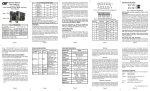
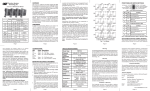
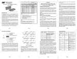
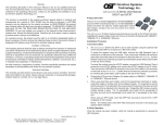
Model #
4470/90-x
4471/91-x
4472/92-x
4473/93-x
4474/94-x
Fiber Type
MM, SC, 1310nm
SM, SC, 1310nm
MM, ST, 1310nm
SM, ST, 1310nm
SM, SC, 1310nm, LH
Max Distance
5km
30km
5km
30km
60km
Power Options (-x):
-0 No power adapter included (chassis module)
-1 110 Volt / 60 Hz
-2 110-230 Volt / 50 Hz
Mounting Options
WARNING!
Before inserting the Power Adapter, verify that the
power on the unit is appropriate for your AC line
voltage source.
Attach the BNC to the FlexPoint T1/E1 converter and attach
the other end of the BNC to the network equipment.
Note: Use copper cables that are compliant with the
specifications that are outlined in copper cable specifications.
Switch Settings:
UTP DCE/DTE setting
Mounting instructions:
The FlexPoint Fiber Converter can be solo-mounted using
a wall-mounting kit, or rack-mounted using a 5-unit shelf,
or a high-density FlexPoint 14-Unit Power-Redundant
Chassis.
The UTP DCE/DTE switch is used to eliminate the need for
crossover and custom cables to connect devices together when
using the RJ-45/48 port. Set this switch to DCE to use a
straight-through cable and to DTE when a crossover-cable
would be required.
Fiber Optic Cable Attachment:
Connect the fiber cables between the FlexPoint T1/E1
converters. The transmit (Tx) must attach to the receive
side and the receive (Rx) must attach to the transmit side.
Note: Use fiber cables that are compliant with the
specifications that are outlined in fiber cable specifications.
DCE
Twisted 1 RTIP
Pair #1 2 RRING
TTIP
TRING
Twisted 1 RTIP
Pair #1 2 RRING
TTIP
TRING
Twisted 4 TTIP
Pair #2 5 TRING
RTIP
RRING
Twisted 4 TTIP
Pair #2 5 TRING
RTIP
RRING
T1/E1 Copper line configuration settings
Connect to the RJ-45/48 connector on the FlexPoint T1/
E1 converter via a category 3 or better cable (Category
5 is recomended) and attach the other end to the network
The T1/E1 copper line codes and line lengths are configured
using dip switches located on the side of the FlexPoint T1/E1
media converter.
Local loop-back and Remote loop-back
LED Indicators
When both Local and Remote Loop-back are set to the
Normal position, the FlexPoint T1/E1 uses the default B8ZS
data format. When both switches are turned to their On
position, it uses the AMI data format.
LED Color
Power:
Yellow
Fiber:
Green
Copper Cable Specifications:
Twisted-Pair cable for T1
FlexPoint Wall-Mounting Hardware Kit
FlexPoint 18 to 72VDC Stand-Alone Power Supply
FlexPoint DC Converter Wall-Mounting Kit (for 4384)
FlexPoint 14-Unit 48VDC Power-Redundant Chassis
FlexPoint 5-Unit Rack-Mounting Shelf
FlexPoint 14-Unit AC Power-Redundant Chassis
Transmit/force 1’s to fiber
This switch is used to insert an “all ones” pattern into the
data stream being transmitted out of the fiber port on the
FlexPoint T1/E1 converter. Data being received on the coax
or twisted pair will be disabled and data being received on
the fiber is passed through to the coax or twisted pair side.
By returning the switch to the normal position the unit will
resume to normal operation.
Transmit/force 1’s to Coax or UTP
This switch is used to insert an “all ones” pattern into the
data stream being transmitted out of the coax or twisted
pair on the FlexPoint T1/E1 converter. Data being received
on the fiber will be disabled and data being received on
the coax or twisted pair is passed through to the fiber side.
By returning the switch to the normal position the unit will
resume to normal operation.
Alarm Relay Contacts
The FlexPoint T1/E1 features dry relay contacts for
optionally connecting the it into a separate T1/E1 alarm
circuit. The relay closes when a loss of power or when
signal detect is lost to the copper or fiber connection.
Relay
RJ-45/RJ-48
3
6
Operational rating on relay pins 3 & 6: 0-220VDC max 2A
UTP/Coax:
Green
Status
Description
On
Power applied
Off
On
Blink
No signal detect
Signal detect
All ones received
Off
On
Blink
No signal detect
Signal detect
All ones received
Off
On
Blink
Fast Blink
Normal operation
L/LB or All 1’s Test mode
R+L/LB Received master
R+L/LB Received slave
Test:
Green
Fiber Cable Specifications:
Multimode
Cable:
Wavelength:
Max Distance:
50/125, 62.5/125, 100/140 μm
1310nm
5km
Singlemode
Cable:
Wavelength:
Max Distance:
9/125 μm
1310nm
30km
Singlemode long-haul
Cable:
Wavelength:
Max Distance:
9/125 μm
1310nm
60km
Gauge
Impedance
Impedance characteristic
Maximum distance
22 to 24 AWG
100 Ω + 10%
2.6 dB / 100m @ 1.0 MHz
6,000 ft
Twisted-Pair cable for E1
Gauge
Impedance
Impedance characteristic
Maximum distance
22 to 24 AWG
120 Ω + 10%
2.6 dB / 100m @ 1.0 MHz
8,000 ft
Coax cable for E1
Gauge
Impedance
Impedance characteristic
Maximum distance
0’ - 133’
133’ - 266’
266’ - 399’
399’ - 533’
533’ - 655’
L
L
L
L
L
L
L
L
L
K
L
L
K
K
L
L
K
L
K
L
T1 DS-1
T1 DS-1
T1 DS-1
T1 DS-1
RJ-45/48
RJ-45/48
RJ-45/48
RJ-45/48
0 dB
-7.5 dB
-15.0 dB
-22.5 dB
L
L
L
L
L
K
K
K
L
L
K
K
L
K
L
K
E1 75 Ω
E1 120 Ω
E1 75 Ω
E1 120 Ω
Coax/BNC
RJ-45/48
Coax/BNC
RJ-45/48
Standard
Standard
Extended
Extended
K
K
K
K
L
L
L
L
L
L
K
K
L
K
L
K
Operational switch settings and functions
DTE
Copper Cable Attachment:
RJ-45/RJ-48 T1/E1 connector
4380
4384
4381
4385
4392
4395
RJ-45/48
RJ-45/48
RJ-45/48
RJ-45/48
RJ-45/48
22 to 24 AWG
75 Ω + 10%
2 dB / 100m @ 1.0 MHz
8,000 ft
For product specifications refer to the product data sheet.
Technical Support:
For help with this product, contact our Tech. Support:
Phone:
(949) 250-6510
Fax:
(949) 250-6514
Address: Omnitron Systems Technology, Inc.
140 Technology Drive, #500
Irvine, CA 92618 USA
E-mail:
[email protected]
URL:
http://www.omnitron-systems.com
The following operational switches located on the front of
the FlexPoint T1/E1 converter are to assist in installation
and fault isolation.
This switch will set the FlexPoint T1/E1 converter in a
loop-back mode on both the fiber and copper connections.
By returning the switch to the normal position the unit will
resume to normal operation.
Cu-Rx
FO-Tx
Cu-Tx
FO-Rx
Loopback Enabled
Remote loop-back (R+L/LB)
This switch will allow the entire fiber segment to be tested
at either of the FlexPoint T1/E1 converters without having
to set switches on both units. When set in this mode the
local unit is switched to a local loop-back mode. The fiber
Tx port will be further encoded to carry a remote loop-back
protocol. This remote loop-back will set the far end
FlexPoint T1/E1 converter to remote loop-back mode and
return a signal to the sending unit. An LED on the local
and remote FlexPoint T1/E1 converters will show a
confirmation that the fiber segment is communicating
properly between devices. By returning the switch to the
normal position it will return to normal operation.
Cu-Rx
Local Dual Loop Back
Remote & Local Loop Back
Force 1’s to Fiber
Force 1’s Copper
Normal
Cu-Tx
FO-Tx
FO-Rx
Cu-Tx
FO-Rx
FO-Tx
Cu-Rx
Remote Loop Request
Over Fiber
Warning
Limitation of Warranty
The operating description in this Instruction Manual is for use
by qualified personnel only. To avoid electrical shock, do not
perform any servicing of this unit other than that contained in
the operating instructions, unless you are qualified and certified
to do so by Omnitron Systems Technology, Inc.
The foregoing warranty shall not apply to defects resulting
from improper or inadequate use and/or maintenance of the
equipment by Buyer, Buyer-supplied equipment, Buyer-supplied
interfacing, unauthorized modifications or tampering with
equipment (including removal of equipment cover by personnel
not specifically authorized and certified by Omnitron), or misuse,
or operating outside the environmental specification of the
product (including but not limited to voltage, ambient
temperature, radiation, unusual dust, etc.), or improper site
preparation or maintenance.
No other warranty is expressed or implied. Omnitron specifically
disclaims the implied warranties of merchantability and fitness
for any particular purpose.
Caution
All user-required operations can be performed without opening
the unit. Never attempt to open or remove the cover or tamper
with the unit.
Warranty
This product is warranted to the original purchaser against
defects in material and workmanship for a period of TWO
YEARS from the date of shipment. A LIFETIME warranty may
be obtained by the original purchaser by REGISTERING this
product with Omnitron within 90 days from the date of shipment.
TO REGISTER, COMPLETE AND MAIL OR FAX THE
REGISTRATION PORTION OF THIS INSTRUCTION
MANUAL TO THE INDICATED ADDRESS. Or you may
register your product on the Internet at http://www.omnitronsystems.com. During the warranty period, Omnitron will, at its
option, repair or replace a product which is proven to be
defective.
For warranty service, the product must be sent to an Omnitron
designated facility, at Buyer’s expense. Omnitron will pay the
shipping charge to return the product to Buyer’s designated
US address using Omnitron’s standard shipping method.
Exclusive Remedies
The remedies provided herein are the Buyer’s sole and
exclusive remedies. Omnitron shall not be liable for any direct,
indirect, special, incidental, or consequential damages, whether
based on contract, tort, or any legal theory.
Form: 040-04470-002D 11/07
Please complete both sides of this form
The FlexPoint T1/E1 connects T1 and E1 devices, such as
PBXs, CSUs and routers, via multimode (MM) or single-mode
(SM) fiber. Designed to extend the standard T1/E1 twisted pair
or Coax network distances over fiber, this converter provides
protection from environmental noise and effectively increases
high-speed network reliability. The following models are
described here.
T1 DSX-1
T1 DSX-1
T1 DSX-1
T1 DSX-1
T1 DSX-1
Local loop-back (L/LB)
Please complete both sides of this form
Description:
Switch Positions
1 2 3 4
Name: _________________________________________________
Company: ______________________________________________
Address: ______________________________________________
______________________________________________
City: ___________________ State: _______ Zip Code: ________
Country: _______________________________________________
Phone: ____________________ Fax: _______________________
E-mail: _________________________________________________
Coax E1 Connector
Distances
Model: _________________________________________________
Serial Number: ______________ Purchase Date: ______________
Purchased From: _________________________________________
Address: ______________________________________________
City: ___________________ State: _______ Zip Code: ________
Country: _______________________________________________
Comments and Suggestions: _______________________________
______________________________________________________
______________________________________________________
User Instructions
Port Type
User Warranty Registration
T1/E1 Copper to Fiber
Converters
Line Type
Please register on-line @ http://www.omnitron-systems.com or complete both sides
and mail or fax this registration form to:
Omnitron Systems Technology, Inc.
140 Technology Drive, #500
Irvine, CA 92618, USA
Fax: (949) 250-6514
FlexPoint
equipment. (The twisted pair connection requires two active
pairs in a T1/E1 environment. The active pairs are pins
1&2 and pins 4&5. Only dedicated wire pairs should be
used for the active pins.) Set the UTP DCE / DTE switch
for the RJ-45/48 port to the appropriate setting.
Note: Use copper cables that are compliant with the
specifications that are outlined in copper cable specifications.
User Warranty Registration
TM
1. When Using in a stand-alone configuration, this product
is intended to be and must be used only with a Listed
Direct Plug-In Power Unit marked “Class 2” and rated
at 9VDC, 1 Amp.
2. This product should always be used only with Omnitron
Supplied Power Unit model numbers 9113-PS or 9115-PS.
Please register on-line at http://www.omnitron-systems.com or complete both sides
and return this form to Omnitron Systems.
Power Adapter Notice