1
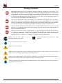
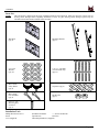
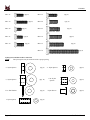
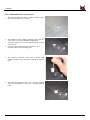
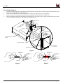
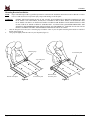
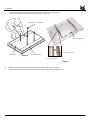
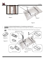
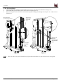
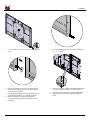
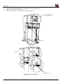
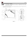
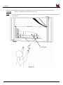
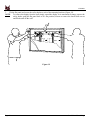
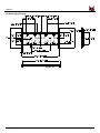
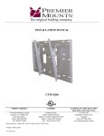
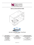
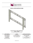
INSTALLATION INSTRUCTIONS
Universal Tilt Wall Mount
Model: CTM-MS4
NORTH AMERICA
3130 East Miraloma Avenue
Anaheim, CA 92806 USA
USA and Canada
Phone: 1.800.368.9700
Fax: 1.800.832.4888
Other Locations
Phone: (001).714.632.7100
Fax: (001).714.632.1044
9531-000-331-07
EUROPE
Swallow House,
Shilton Industrial Estate,
Shilton, Coventry, England CV79JY
Phone: +44 (0) 2476 614700
Fax: +44 (0) 2476 614710
AUSTRALIA AND OCEANIA
Distributed by Amber Technology Limited
Unit B, 5 Skyline Place
Frenchs Forest NSW 2086
Australia
Phone: +61 2 9452 8600 Sydney Office
Toll Free: 1-800-368-9700
Email: [email protected]
CTM-MS4
Table of Contents
Warning Statements ........................................................................................................................................- 3 Parts List ...........................................................................................................................................................- 4 Installation Tools ..............................................................................................................................................- 4 How to Determine the Correct Spacer ...........................................................................................................- 6 Mounting Bracket Installation .......................................................................................................................- 8 CTM-MS4 Installation ..................................................................................................................................- 11 Installing the Flat Panel Display (CTM-MS4) ............................................................................................- 14 Technical Specifications ................................................................................................................................- 17 Warranty ........................................................................................................................................................- 18 Contact Premier Mounts ...............................................................................................................................- 18 Notes ................................................................................................................................................................- 18 -
Installation Manual
Page - 2 -
CTM-MS4
Warning Statements
PREMIER MOUNTS DOES NOT WARRANT AGAINST DAMAGE CAUSED BY THE USE OF ANY
PREMIER MOUNTS PRODUCT FOR PURPOSES OTHER THAN THOSE FOR WHICH IT WAS DESIGNED
OR DAMAGE CAUSED BY UNAUTHORIZED ATTACHMENTS OR MODIFICATIONS, AND IS NOT
RESPONSIBLE FOR ANY DAMAGES, CLAIMS, DEMANDS, SUITS, ACTIONS OR CAUSES OF ACTION
OF WHATEVER KIND RESULTING FROM, ARISING OUT OF OR IN ANY MANNER RELATING TO
ANY SUCH USE, ATTACHMENTS OR MODIFICATIONS.
THE WALL STRUCTURE MUST BE CAPABLE OF SUPPORTING 300 LBS. IF NOT, THE WALL
STRUCTURE MUST BE REINFORCED. PROPER INSTALLATION PROCEDURE BY A QUALIFIED
SERVICE TECHNICIAN, AS OUTLINED IN THE INSTALLATION INSTRUCTIONS, MUST BE ADHERED
TO. FAILURE TO DO SO COULD RESULT IN SERIOUS PERSONAL INJURY, OR EVEN DEATH.
SAFETY MEASURES MUST BE PRACTICED AT ALL TIMES DURING THE INSTALLATION OF THIS
PRODUCT. USE PROPER SAFETY GEAR AND TOOLS FOR THE INSTALLATION PROCEDURE TO
PREVENT PERSONAL INJURY.
PRIOR TO THE INSTALLATION OF THIS PRODUCT, THE INSTALLATION INSTRUCTIONS SHOULD
BE READ AND COMPLETELY UNDERSTOOD. THE INSTALLATION INSTRUCTIONS MUST BE READ
TO PREVENT PERSONAL INJURY AND PROPERTY DAMAGE. KEEP THESE INSTALLATION
INSTRUCTIONS IN AN EASILY ACCESSIBLE LOCATION FOR FUTURE REFERENCE.
Indicates that the power plug is to be
disconnected from the power outlet.
Contact Premier Mounts with any questions - (800)
368-9700
Safety precautions must be taken at all times.
Warning and Caution statements.
Do not install on a structure that is prone to vibration, movement or chance of impact. Failure to do so could result in
damage to the flat panel display and/or damage to the mounting surface.
Do not install near heater, fireplace, direct sunlight, air conditioning or any other source of direct heat energy. Failure to
do so may result in damage to the flat panel display and could increase the risk of fire.
At least two qualified people should perform the installation procedure. Injury and/or damage can result from dropping or
mishandling the flat panel display.
Page - 3 -
Installation Manual
CTM-MS4
Parts List
NOTE:
This wall mount is shipped with all proper installation hardware and components. Make sure that none of these parts are
missing and/or damaged before beginning installation. If there are parts missing and/or damaged, please stop the
installation and contact Premier Mounts (800-368-9700).
Wall Plate
(Qty 2)
Mounting Brackets
(Qty 2)
5/16” Flat
Washers
(Qty 12)
5/16” x 3” Lag Bolts
(wooden studs only)
(Qty 12)
M6 x 12mm
Safety Knobs
(Qty 2)
Griplate™ (Qty 8)
M8 x 16mm
Hex Head Bolt
(Qty 2)
M8 Hex Nut
(Qty 2)
5/16” x 1-1/4”
Mounting Rod
Set Screw
(Qty 1)
Installation Tools
Phillips Head Screw Driver
Pencil
Level (Supplied)
Installation Manual
Soft Material/ Blanket
½ ” Socket and Wrench
Tape Measure
Drill Gun
Thread Depth Indicator (Supplied)
Page - 4 -
CTM-MS4
M5 x 25
(Qty 8)
M5 x 30
M6 x 20
M6 x 25
M6 x 30
(Qty 8)
(Qty 8)
(Qty 8)
(Qty 8)
(Qty 8)
M6 x 35
(Qty 8)
M8 x 20
(Qty 8)
M8 x 25
(Qty 8)
M8 x 30
M8 x 35
(Qty 8)
(Qty 4)
M8 x 70
Nylon spacers and flat washers’ actual size
NOTE:
The nylon spacers may be stacked to achieve proper spacing.
¼” Nylon Spacers
(Qty 8)
¼” Nylon Spacers
(Qty 8)
½” Nylon Spacers
(Qty 12)
9/16” Nylon
Spacers
(Qty 8)
5/16” Flat Washers
(Qty 8)
Nylon Sleeves
(Qty 8)
1” Nylon Spacers
(Qty 8)
Page - 5 -
Installation Manual
CTM-MS4
How to Determine the Correct Spacer
1.
The following illustration shows a display mounting surface
that will not need the use of a spacer.
2.
The illustration shows a display mounting surface that will
need a spacer to correctly install the mounting plate.
Anytime a display has a recessed mounting point, a spacer
must be used.
Select the spacer(s) that will create a flush and level
mounting surface for the mounting plate.
3.
4.
5.
The following illustration shows how a thread depth
indicator should be used to determine which spacer should be
used.
6.
The following illustration shows how a correctly installed
spacer and mounting screw will sit in a recessed mounting
point.
Installation Manual
Page - 6 -
CTM-MS4
Thread Depth Indicator
1.
2.
3.
4.
Insert the thread depth indicator (supplied) through the thread inserts found on the back of the flat panel to make sure the inserts
measure the same full depth and mark it (Figure 1).
Locate the correct diameter screw for the thread insert. Compare your marking to the screws (supplied).
If your selected screw is longer than the marking on the thread depth indicator, DO NOT USE this screw.
The screw length must not bypass the marking. Select another screw size (Figure 2 and 3), until you find one that comes closest
to your mark without going past the mark on the Thread Depth Indicator.
Inverted flat panel
display
Marking the depth
Thread depth
indicator
Thread insert
Figure 1
Screw
Thread depth
indicator
Marking
Figure 2
Installation Manual
Thread depth
indicator
Screw
Marking
Figure 3
Page - 7 -
CTM-MS4
Mounting Bracket Installation
NOTE:
Proper installation procedure by qualified personnel as outlined in the installation instructions must be adhered to. Failure
to do so could result in serious personal injury and possible damage to the flat panel.
WARNING:
1.
2.
INVERT THE FLAT PANEL PLACE IT ON A SOFT, FLAT SUFRACE TO PREVENT DAMAGE TO THE
FLAT PANEL. USE A BLANKET, FOAM, ETC. FAILURE TO DO SO WILL RESULT IN DAMAGING THE
FLAT PANEL. DO NOT LAY THE FLAT PANEL ON THE FLOOR WITHOUT ANY PROTECTION TO THE
GLASS. THE FLAT PANEL IS HEAVY AND FRAGILE. AT LEAST TWO QUALIFIED PERSONNEL ARE
STRONGLY RECOMMENDED FOR INSTALLATION OF THIS PRODUCT. FAILURE TO DO SO COULD
RESULT IN SERIOUS INJURY AND POSSIBLE DAMAGE TO THE FLAT PANEL.
Once the flat panel is inverted, use a measuring tape to find the center of your flat panel measuring from outside to outside of
the flat panel (Figure 4).
Using a pencil lightly mark the center of your flat panel (Figure 5).
Measuring tape
Inverted flat panel
Top of flat panel
CL
Bottom of flat panel
Inverted flat panel
Figure 4
Page - 8 -
CL
Mark the center
of the flat panel
Figure 5
Installation Manual
CTM-MS4
3.
4.
Install the nylon spacers (if needed) to the mounting points on the flat panel (Figure 6).
Lay the mounting brackets (stamped arrows facing out) - (Figure 7).
Nylon Spacers, If Applicable
Bottom of Flat Panel
Notched Cut Outs
Center Mark
Figure 6
Inverted Flat Panel
Arrows Facing Out
Figure 7
5.
6.
Match the center of viewing guide with the centerline you marked in Step 1 (Figure 8).
The mounting brackets are designed with a center of viewing guide on the outside (Figure 9).
Installation Manual
Page - 9 -
CTM-MS4
Mounting Bracket
Notched Cut Out
Figure 8
Bottom of the
Flat Panel
Figure 9
7.
8.
The Griplate™ has M4, M5 M6 and M8 hole patterns to fit the hardware that your flat panel requires.
EXAMPLE: If your plasma uses M8 x 20 Phillip screws, use the M8 mounting points (Figure 10).
Once the mounting brackets are aligned, secure the Griplate™ to the flat panel. Use (1) Griplate™ per mounting point (Figure
11).
NOTE:
The dimples of the top Griplate™ have to be facing up and the bottom Griplate™ dimples must be facing down.
Phillips Screw Driver
Dimples Facing Up
M4 M5 M6 M8
Figure 10
Dimples Facing Up
Inverted Flat Panel
Dimples Facing Down
Dimples Facing Down
Page - 10 -
Figure 11
Installation Manual
CTM-MS4
CTM-MS4 Installation
1.
2.
3.
Using a (commercially available) wood stud finder, locate the 16" or 24" stud centers behind the wall (Figure 12).
Once found, make a pencil marking on the center of the wood studs (Figure 13).
Place the wall plate to the reference line and mark the lag bolt mounting points through the wall plate slots on the wall (see
NOTE below).
Mark the wall
and the center
of the wood
studs.
Wood Stud Finder
(Commercially available)
16"
16"
Measure and
mark the
viewing height
desired on the
wall.
Wood studs
behind the
wall
structure.
Figure 12
NOTE:
Figure 13
Three studs that are 24” apart will need nine (9) lag bolts. Four studs that are 16” apart will need twelve (12) lag bolts.
Installation Manual
Page - 11 -
CTM-MS4
4.
Use a screwdriver to remove the lower mounting rod
screw.
5.
Once the mounting rod screw is removed, insert one
(1) 1 ¼˝ set screw.
6.
Once the mounting rod set screw has been inserted
into the first wall plate, place the second wall plate
next to the first wall plate.
Line up the mounting hole with the mounting rod set
screw and then slide the two wall plates together.
Slide the mounting rod onto the wall plate set
screw and slowly thread the rod onto the set screw
until tight.
9.
Insert two (2) M8 x 16mm hex head bolts through the
two holes and secure with two (2) M8 hex nuts.
7.
8.
Page - 12 -
10. Once the bolt and nut have been attached and finger
tightened, use a wrench (not supplied) to tighten
them.
Installation Manual
CTM-MS4
11.
12.
13.
Level the wall plate with the reference arrow pointing up to the ceiling (Figure 15).
Drill ¼" pilot holes to the marked wall.
Secure the plate using the 5/16" lag bolts and flat washers (Figure 16).
Mark the mounting slot
openings
16"
Wall Plates
Figure 15
Wall Plate
Figure 16. Wood Installation
Installation Manual
5/16” x 3” Lag
Bolts
Page - 13 -
CTM-MS4
Installing the Flat Panel Display (CTM-MS4)
WARNING:
1.
AT LEAST TWO QUALIFIED PERSONNEL ARE STRONGLY RECOMMENDED FOR INSTALLATION
OF THIS PRODUCT. FAILURE TO DO SO COULD RESULT IN SERIOUS INJURY AND POSSIBLE
DAMAGE TO THE FLAT PANEL.
Raise the flat panel with the mounting brackets secured to the flat panel and insert the top hooks over the upper rod. The lower
hooks should rest on the lower rod (Figure 17).
Wall Plate
Top
Bottom
Figure 17
Page - 14 -
Installation Manual
CTM-MS4
2.
Make any lateral shift adjustment and lock it by tightening the screws found on the bottom of the mounting brackets.
CAUTION:
NOTE:
Do not over tighten the screws to the rods (Figure 18).
To remove the display from the wall simply loosen the screws using a Phillips screwdriver and lift the unit of the
wall carefully.
Lateral Shift
Wall Plate
Figure 18
Installation Manual
Page - 15 -
CTM-MS4
3.
Tilt the flat panel and secure the safety knobs to each of the mounting brackets (Figure 19).
NOTE: To remove the display from the wall simply extend the display to its maximum tilt range, remove the
safety knobs, push the flat panel back to it’s flat position, loosen or remove the lateral shift screws
and lift the unit off the wall.
Figure 19
Page 16
Installation Manual Page
CTM-MS4
Technical Specifications
Figure 20
Installation Manual
Page 17
CTM-MS4
Warranty
Limited Lifetime Warranty
All Premier Mounts products carry a limited lifetime warranty from ship date against defects in materials and workmanship. Premier
Mounts is not liable for improper installation that results in damage to mounts, adapters, display equipment or personal injury.
DISCLAIMER OF WARRANTY.
THE FOREGOING WARRANTY IS IN LIEU OF ALL OTHER WARRANTIES, EXPRESS OR IMPLIED, INCLUDING
BUT NOT LIMITED TO THE IMPLIED WARRANTIES OF MERCHANTABILITY AND FITNESS FOR A
PARTICULAR PURPOSE.
Contact Premier Mounts
In the event of missing and/or damage equipment, or technical questions, the following information can help in the completion of the
installation.
Customer Service – (800) 368-9700
Technical Support – [email protected]
Notes
NORTH AMERICA
3130 East Miraloma Avenue
Anaheim, CA 92806 USA
USA and Canada
Phone: 1.800.368.9700
Fax: 1.800.832.4888
Other Locations
Phone: (001).714.632.7100
Fax: (001).714.632.1044
Page 18
9531-000-331-07
EUROPE
Swallow House,
Shilton Industrial Estate,
Shilton, Coventry, England CV79JY
Phone: +44 (0) 2476 614700
Fax: +44 (0) 2476 614710
AUSTRALIA AND OCEANIA
Distributed by Amber Technology Limited
Unit B, 5 Skyline Place
Frenchs Forest NSW 2086
Australia
Phone: +61 2 9452 8600 Sydney Office
Toll Free: 1-800-368-9700
Email: [email protected]
Installation Manual