1
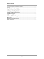
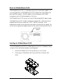
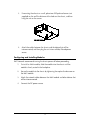
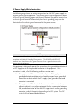
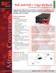
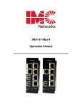
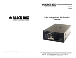
IE-MediaChassis/2 (DC)
Operation Manual
FCC Radio Frequency Interference Statement
This equipment has been tested and found to comply with the limits for a Class A computing device, pursuant to Part 15 of the FCC Rules.
These limits are designed to provide reasonable protection against harmful interference when the equipment is operated in a commercial
environment. This equipment generates, uses and can radiate radio frequency energy and, if not installed and used in accordance with the
instruction manual, may cause harmful interference to radio communications. Operation of this equipment in a residential area is likely to
cause harmful interference in which the user will be required to correct the interference at his own expense.
Any changes or modifications not expressly approved by the manufacturer could void the user’s authority to operate the equipment.
The use of non-shielded I/O cables may not guarantee compliance with FCC RFI limits. This digital apparatus does not exceed the Class A
limits for radio noise emission from digital apparatus set out in the Radio Interference Regulation of the Canadian Department of
Communications.
Le présent appareil numérique n’émet pas de bruits radioélectriques dépassant les limites applicables aux appareils numériques de classe A
prescrites dans le Règlement sur le brouillage radioélectrique publié par le ministère des Communications du Canada.
Warranty
IMC Networks warrants to the original end-user purchaser that this product, EXCLUSIVE OF SOFTWARE, shall be free
from defects in materials and workmanship under normal and proper use in accordance with IMC Networks' instructions
and directions for a period of six (6) years after the original date of purchase. This warranty is subject to the limitations set
forth below.
At its option, IMC Networks will repair or replace at no charge the product which proves to be defective within such
warranty period. This limited warranty shall not apply if the IMC Networks product has been damaged by unreasonable
use, accident, negligence, service or modification by anyone other than an authorized IMC Networks Service Technician
or by any other causes unrelated to defective materials or workmanship. Any replaced or repaired products or parts carry
a ninety (90) day warranty or the remainder of the initial warranty period, whichever is longer.
To receive in-warranty service, the defective product must be received at IMC Networks no later than the end of the
warranty period. The product must be accompanied by proof of purchase, satisfactory to IMC Networks, denoting
product serial number and purchase date, a written description of the defect and a Return Merchandise Authorization
(RMA) number issued by IMC Networks. No products will be accepted by IMC Networks which do not have an RMA
number. For an RMA number, contact IMC Networks at PHONE: (800) 624-1070 (in the U.S and Canada) or (949) 4653000 or FAX: (949) 465-3020. The end-user shall return the defective product to IMC Networks, freight, customs and
handling charges prepaid. End-user agrees to accept all liability for loss of or damages to the returned product during
shipment. IMC Networks shall repair or replace the returned product, at its option, and return the repaired or new
product to the end-user, freight prepaid, via method to be determined by IMC Networks. IMC Networks shall not be
liable for any costs of procurement of substitute goods, loss of profits, or any incidental, consequential, and/or special
damages of any kind resulting from a breach of any applicable express or implied warranty, breach of any obligation
arising from breach of warranty, or otherwise with respect to the manufacture and sale of any IMC Networks product,
whether or not IMC Networks has been advised of the possibility of such loss or damage.
EXCEPT FOR THE EXPRESS WARRANTY SET FORTH ABOVE, IMC NETWORKS MAKES NO OTHER WARRANTIES,
WHETHER EXPRESS OR IMPLIED, WITH RESPECT TO THIS IMC NETWORKS PRODUCT, INCLUDING WITHOUT
LIMITATION ANY SOFTWARE ASSOCIATED OR INCLUDED. IMC NETWORKS SHALL DISREGARD AND NOT BE
BOUND BY ANY REPRESENTATIONS OR WARRANTIES MADE BY ANY OTHER PERSON, INCLUDING EMPLOYEES,
DISTRIBUTORS, RESELLERS OR DEALERS OF IMC NETWORKS, WHICH ARE
INCONSISTENT WITH THE WARRANTY SET FORTH ABOVE. ALL IMPLIED WARRANTIES INCLUDING THOSE OF
MERCHANTABILITY AND FITNESS FOR A PARTICULAR PURPOSE ARE HEREBY LIMITED TO THE DURATION OF THE
EXPRESS WARRANTY STATED ABOVE.
Every reasonable effort has been made to ensure that IMC Networks product manuals and promotional materials
accurately describe IMC Networks product specifications and capabilities at the time of publication. However, because of
ongoing improvements and updating of IMC Networks products, IMC Networks cannot guarantee the accuracy of printed
materials after the date of publication and disclaims liability for changes, errors or omissions.
ii
Table of Contents
FCC Radio Frequency Interference Statement ........................................................ ii
Warranty................................................................................................................ ii
About the IE-MediaChassis/2 (DC)..........................................................................1
Installing the IE-MediaChassis/2 (DC)......................................................................1
Configuring and Installing Modules.........................................................................2
DC Power Supply Wiring Instructions.....................................................................3
Rackmount Precautions..........................................................................................4
DC Power Supply Precautions................................................................................5
IMC Networks Technical Support...........................................................................6
Specifications .........................................................................................................6
Electrostatic Discharge Precautions.........................................................................7
Safety Certifications................................................................................................8
iii
About the IE-MediaChassis/2 (DC)
The IE-MediaChassis/2 (DC) is a stand-alone chassis for use with iMcV modules. As
an unmanaged chassis, the IE-MediaChassis/2 (DC) supports two single-wide or one
dual-wide iMcV module. All iMcV modules, with the exception of the SNMP
management card, will function properly in this chassis.
The IE-MediaChassis/2 (DC) contains an internal Telco compatible DC power supply.
The iMediaChassis/2 (DC) includes a temperature triggered fan. When the internal
temperature of the chassis reaches 86° F (30° C) the fan is activated. As the
temperature increases the fan drive duty cycle adjusts to increase the fan speed. You
can test the fan operation by depressing the fan test switch on the back of the chassis.
Installing the IE-MediaChassis/2 (DC)
Use the IE-MediaChassis/2 (DC) as a table-top chassis, mount in a Rackmount shelf,
or mount it to a wall surface (brackets are not required).
1.
Install the IE-MediaChassis/2 (DC) by placing it on a flat surface.
2.
If mounting on a Rackmount shelf, align screw holes and secure with
screws.
1
3.
If mounting the chassis on a wall, place two #10 panhead screws (not
supplied) on the wall the distance of the holes on the chassis, and then
hang the unit on the screws.
4.
Attach the cables between the chassis and the device that will be
interconnected, and then plug the unit into a reliable, filtered power
source.
Configuring and Installing Modules
IMC Networks recommends turning the chassis power off before proceeding.
1.
To install an iMcV module, slide the module into the chassis until the
module is firmly seated in the backplane.
2.
Secure the module to the chassis by tightening the captive thumb screw on
the iMcV module.
3.
Attach the network cables between the iMcV module and other devices that
will be interconnected.
4.
Connect the DC power source.
2
DC Power Supply Wiring Instructions
The following image shows the wiring configuration for a 48 VDC power supply in a
negative ground system application. For positive ground system applications remove
the chassis ground shorting jumper and connect it between the positive terminal and
the chassis ground terminal. Alternatively, the chassis grounding jumper can be
eliminated and the chassis ground connected at the power source.
NOTE
Incorrect wiring will result in chassis malfunction. The IE-MediaChassis/2 (DC) is
compliant with Isolated Grounding Plane practices. The POSITIVE and NEGATIVE
terminals are isolated from chassis ground and must have a ground reference at the
power-sourcing equipment.
This equipment is designed to permit the connection of the grounded conductor of
the DC supply circuit to the grounded conductor at the equipment. If this
connection is made, all of the following conditions must be met:
1.
This equipment shall be connected directly to the DC supply system
grounded electrode conductor or to a bonding jumper from a grounded
terminal bar or bus to which the DC supply system grounding electrode
conductor is connected.
2.
This equipment shall be located in the same immediate area (such as,
adjacent cabinets) as any other equipment that has a connection between
the grounded conductor of the same DC supply circuit and the grounding
conductor, and also the point of grounding of the DC system. The DC
system shall not be grounded elsewhere.
3
3.
The DC supply source shall be located within the same premises as this
equipment.
4.
Switching or disconnecting devices shall not be in the grounded circuit
conductor between the DC source and the point of connection of the
grounding electrode conductor.
Rackmount Precautions
1.
Elevated Operating Ambient - If installed in a closed or multi-unit rack
assembly, the operating ambient temperature of the rack environment may
be greater than room ambient. Therefore, consideration should be given to
installing the equipment in an environment compatible with the maximum
ambient temperature (Tma) specified by the manufacturer.
2.
Reduced Air Flow - Installation of the equipment in a rack should be such
that the amount of air flow required for safe operation of the equipment is
not compromised.
3.
Mechanical Loading - Mounting of the equipment in the rack should be
such that a hazardous condition is not achieved due to uneven mechanical
loading.
4.
Circuit Overloading - Consideration should be given to the connection of
the equipment to the supply circuit and the effect that overloading of the
circuits might have on overcurrent protection and supply wiring.
Appropriate consideration of equipment nameplate ratings should be used
when addressing this concern.
5.
Reliable Grounding - Reliable grounding of rackmounted equipment
should be maintained. Particular attention should be given to supply
connections other than direct connections to the branch circuit (e.g. use of
power strips).
4
DC Power Supply Precautions
The following precautions must be observed when installing the chassis model with
an internal DC power supply.
1.
2.
Check nameplate ratings to ensure there is no overloading of supply circuits that
could effect over current protection and supply wiring.
In addition, the following must be observed:
a. Connect the equipment to a 35 to 75 VDC power source that is electrically
isolated from the alternating current source.
b. Route input wiring to terminal block and secure in such a manner that it is
protected from damage and stress. Do not route wiring past sharp edges or
moving parts.
c. Incorporate a readily accessible disconnect device, with a 3mm minimum
contact gap in the fixed wiring.
d. Install only in Restricted Access Areas (dedicated Equipment Rooms,
Equipment closets or the like) in accordance with Articles 110-18, 110-26,
and 110-27 of the National Electric Code, ANSI/NFPA 70.
e. Provide a listed circuit breaker suitable for branch circuit protection of the
wiring and rated maximum 1A @ 48 VDC.
f. For supply connections, use wires suitable for at least 75 ° C.
5
IMC Networks Technical Support
Tel: (949) 465-3000 or (800) 624-1070 (in the U.S. and Canada);
+32-16-550880 (Europe)
Fax: (949) 465-3020
E-Mail: [email protected]
Web: www.imcnetworks.com
Specifications
Environmental
Operating Temperature: -31° F to 176° F (-35° C to 80° C)
Storage Temperature: -67° F to 257° F (-55° C to 125° C)
Humidity: 5 to 95% (non-condensing)
DC Input Specification
Input voltage: 35 to 75 VDC
Input Current: 1.5A
Output Current Capability: 15A @5 VDC
Dimensions
2.23”H x 4.75”W x 7.30”D (5.7 cm H x 12.1 cm W x 18.6 cm D)
Heat Generation
3 BTU/hr. maximum
Fan turns on if the internal temperature exceeds 86° F (30° C)
6
Electrostatic Discharge Precautions
Electrostatic discharge (ESD) can cause damage to your add-in modules. Always
observe the following precautions when installing or handling an add-in module or
any board assembly.
1.
Do not remove unit from its protective packaging until you’re ready to install it.
2.
Wear an ESD wrist grounding strap before handling any module or component.
If you do not have a wrist strap, maintain grounded contact with the system unit
throughout any procedure requiring ESD protection.
3.
Hold boards by the edges only; do not touch the electronic components or gold
connectors.
4.
After removal, always place the boards on a grounded, static-free surface, ESD
pad or in a proper ESD bag. Do not slide the board over any surface.
WARNING! Integrated circuits and fiber optic components are
extremely susceptible to electrostatic discharge damage. Do not
handle these components directly unless you are a qualified service
technician and use tools and techniques that conform to accepted
industry practices.
7
Safety Certifications
UL/CUL: Listed to Safety of Information Technology Equipment, including
Electrical Business Equipment.
CE: The products described herein comply with the Council Directive on
Electromagnetic Compatibility (2004/108/EC) and the Council
Directive on Electrical Equipment Designed for use within Certain
Voltage Limits (2006/95/EC). Certified to Safety of Information
Technology Equipment, Including Electrical Business Equipment. For
further details, contact IMC Networks.
European Directive 2002/96/EC (WEEE) requires that any equipment that bears this
symbol on product or packaging must not be disposed of with unsorted municipal
waste. This symbol indicates that the equipment should be disposed of separately
from regular household waste. It is the consumer’s responsibility to dispose of this
and all equipment so marked through designated collection facilities appointed by
government or local authorities. Following these steps through proper disposal and
recycling will help prevent potential negative consequences to the environment and
human health. For more detailed information about proper disposal, please contact
local authorities, waste disposal services, or the point of purchase for this equipment.
8
19772 Pauling • Foothill Ranch, CA 92610-2611 USA
TEL: (949) 465-3000 • FAX: (949) 465-3020
www.imcnetworks.com
© 2008 IMC Networks. All rights reserved.
The information in this document is subject to change without notice. IMC Networks assumes no responsibility for any
errors that may appear in this document. IE-MediaChassis/2 is a trademark of IMC Networks. Other brands or product
names may be trademarks and are the property of their respective companies.
Document Number 50-80105-01 A3
November 2008
If the product’s part number begins with an “8”, it is compliant with the Restriction of Hazardous Substances (RoHS)
directive.