1
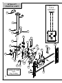
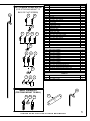
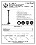
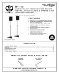
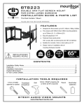
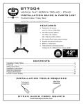
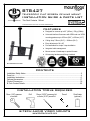
BT8427
TELESCOPIC FLAT SCREEN CEILING MOUNT
INSTALLATION GUIDE & PARTS LIST
This Pack Contains 1 Mount
PLEASE KEEP THIS FOR FUTURE REFERENCE
FEATURES
●
●
Designed for screens up to 65” (165cm) / 70kg (154lbs)
Universal interface fits screens with VESA and non-VESA
mounting patterns up to 970mm (38.2”) x 500mm (19.7”)
●
Ceiling drop: 745mm (29.3”) – 1000mm (39.4”)
●
Easy adjustment of tilt +20°
●
Pre-assembled for simple 3 step installation
●
Integrated cable management
●
Mounts screen in landscape or portrait formats
●
All mounting hardware and fixings included
REG DESIGN NO:4010380
CONTENTS
Installation Safety Notes.....................................................................................................................2
Parts List.............................................................................................................................................4
Installation Instructions.......................................................................................................................6
Optional Accessories........................................................................................................................17
Product Dimensions..........................................................................................................................18
B-Tech Contact Details.....................................................................................................................20
INSTALLATION TOOLS REQUIRED
13mm (1/2") spanner
or socket
Drill
12mm (15/32") masonry bit
or 8mm (5/16") wood bit
Pencil
B-TECH AUDIO VIDEO MOUNTS
www.btechavmounts.com
Stud finder
(optional)
INSTALLATION SAFETY INSTRUCTIONS
CAUTION: This ceiling mount is intended for use only with the maximum
weights indicated. Use with flat screens heavier than the maximum indicated
may result in instability causing possible injury.
Do not attempt to install this product until all instructions and warnings have been read and
properly understood. Please keep these instructions for future reference.
B-Tech International Limited, its distributors and dealers are not liable or responsible for
damage or injury caused by improper installation, improper use or failure to observe these
safety instructions. In such cases, all guarantees will expire.
General
B-Tech International Ltd recommends that a professional AV installer or other suitably qualified
person install this product. Great care must always be taken during installation as most AV
equipment is of a fragile nature, possibly heavy and easily damaged if dropped.
If you do not fully understand the instructions or are not sure how to install this product safely,
then please consult a professional for advice and/or to install this product for you. Failure to
mount this product correctly may cause serious injury or death both during installation and at
any time thereafter.
Do not mount any AV equipment that exceeds the specific weight limit of the product you are
installing. This weight limit will be clearly stated on each product and its packaging and will
vary from product to product.
Product location
Please pay careful attention to where this product is located. Some ceilings are not suitable for
installation.
If located in a public or frequently populated area ensure that the product is out of the
immediate reach of people. If any AV equipment is to be suspended over the likely path or
location of people then great care should be taken to secure all parts of the installation from
falling.
When drilling holes in ceilings it is essential to avoid contact with electrical cables and water or
gas pipes contained within. Use of a good quality live wire detector and hidden object locator is
therefore recommended. Only drill into structures when you are sure it is safe to do so.
Fixing hardware
It is highly recommended that all wall fixing screws be used where supplied and that the
purpose of all other fixing hardware is fully understood. In some cases more AV equipment
fixing hardware will be supplied to accommodate different models of equipment and set up
configurations.
The installer must be satisfied that any supplied fixing hardware is suitable for each specific
installation. If any fixing screws or included hardware are deemed not sufficient for a safe
installation then please consult a professional or your local hardware store.
Hazard limitation
2
When routing cables take advantage of any built in cable management features that the
product might provide and ensure that all cables are tidy and secure. Check to see that any
moving aspect of the product can do so unhindered by any cabling.
Some products have moving parts and the potential to cause injury through the crushing or
trapping of fingers or other body parts.
Particular attention to the nature of moving parts is required especially when assembling
installing and adjusting during set up.
Immediately after installations double-check that the work done is safe and secure. Doublecheck all necessary fixings are present and are of ample tightness.
It is recommended that periodic inspections of the product and its fixing points are made as
frequently as possible to ensure that safety is maintained. If in doubt consult a professional AV
installer or other suitably qualified person.
CS
Společnost B-Tech International Ltd. doporučuje provést instalaci tohoto produktu prostřednictvím odborného
instalátora AV či jinak způsobilé osoby. Společnost B-Tech International Ltd, její distributoři a prodejci nenesou
odpovědnost za škody nebo zranění způsobená nevhodnou instalací. Tento výrobek je nutno umístit do vhodné
konstrukce a používat jen po uvedenou maximální výšku.
DE
B-Tech International Ltd. empfiehlt, dass dieses Produkt durch einen qualifizierten AV-Techniker oder eine
andere Person mit geeigneter Qualifikation installiert wird. B-Tech International Ltd, ihre Distributoren und
Händler können nicht für durch fehlerhafte Montage verursachte Beschädigung oder Verletzung haftbar bzw.
verantwortlich gemacht werden. Dieses Produkt muss auf eine geeignetem Untergrund montiert werden und darf
nur bis zum angegebenen Höchstgewicht verwendet werden.
ES
B-Tech International Ltd. recomienda que un instalador de audio y video profesional u otra persona debidamente
cualificada instalen este producto. B-Tech International Ltd, sus distribuidores y concesionarios no se hacen
cargo ni se responsabilizan de ningún daño o lesión provocados por una instalación inapropiada. Este producto
se debe montar en una estructura adecuada y se debe utilizar soportando solamente hasta el peso máximo
indicado.
FR
B-Tech International Ltd. recommande de confier l’installation de ce produit à un installateur AV professionnel ou
à une autre personne dûment qualifiée. B-Tech International Ltd, ses distributeurs et ses revendeurs ne
sauraient être tenus responsables de tout dégât ou de toute blessure résultant d’une installation incorrecte. Ce
produit doit être monté sur un support approprié et utilisé dans la limite du poids maximum indiqué.
IT
B-Tech International Ltd. consiglia di affidare l’installazione di questo prodotto a un installatore specializzato o ad
altra persona adeguatamente qualificata. B-Tech International Ltd, i suoi distributori e rivenditori non accettano
alcuna responsabilità nei riguardi di eventuali danni o infortuni causati da un’errata installazione. Questo prodotto
deve essere fissato a una struttura idonea e utilizzato unicamente sino al peso massimo indicato.
NL
B-Tech International Ltd. adviseert om dit product te laten installeren door een professionele AV-installateur of
andere hiervoor gekwalificeerde persoon. B-Tech International Ltd, haar distributeurs en dealers zijn niet
aansprakelijk of verantwoordelijk voor schade of letsel die is veroorzaakt door onoordeelkundige installatie. Dit
product moet worden gemonteerd aan een geschikte constructie, waarbij het aangegeven maximum gewicht niet
mag worden overschreden.
PL
Firma B-Tech International Ltd. zaleca, aby ten produkt był instalowany przez profesjonalnych instalatorów AV
lub inny odpowiednio przeszkolony personel. Firma B-Tech International Ltd, jej dystrybutorzy i dealerzy nie
ponoszą odpowiedzialności za uszkodzenia lub obrażenia ciała powstałe w wyniku nieprawidłowej instalacji.
Niniejszy produkt musi być zamontowany na odpowiedniej powierzchni, a podczas użytkowania nie wolno
przekraczać podanego maksymalnego obciążenia.
PT
A B-Tech International Ltd. recomenda que a instalação deste produto seja efectuada por um instalador de AV
profissional ou outra pessoa devidamente habilitada. A B-Tech International Ltd. e os seus distribuidores e
concessionários não são responsáveis por danos ou lesões causados por uma instalação incorrecta. Este
produto tem de ser montado numa estrutura adequada e utilizado somente até ao peso máximo indicado.
RU
Компания B-Tech International Ltd. рекомендует, чтобы установка данного изделия производилась
инженером по установке аудио-видеотехники или другим специалистом с соответствующей
квалификацией. Компания B-Tech International Ltd., ее дистрибьюторы и дилеры не несут ответственности
за повреждения или травмы, полученные в результате неправильной установки. Данное изделие должно
3
BT8427
PARTS LIST
TUBE & TILT
PLATE
ASSEMBLY
4
1
5
18
6
2
10
3
21
22
11
16
8
12
24
24
23
13
10
7
9
20
20
19
21 22
Suitable for loads
up to
70kg (154lbs)
4
23
15
15
23
14
FLAT SCREEN INTERFACE KIT
(FOR ATTACHING MOUNT TO
BACK OF FLAT SCREEN)
25
A
B
M
C
D
E
F
N
REF
1
2
3
4
5
6
7
8
9
10
11
12
13
14
15
16
17
18
19
20
21
22
23
24
25
26
PART NAME
OUTER TUBE
TAPER TRIM
INNER TUBE
COVER PLATE
HEIGHT ADJUSTMENT PIN
M8 x 12mm HEX SCREW
COLLAR
M8 x 15mm GRUB SCREW
M8 x 65mm HEX SCREW
COLLAR COVER
TILT PLATE
HOOK PLATE
INTERFACE PLATE
CROSS RAIL
VERTICAL ARM
LONG TILT ARM
SHORT TILT ARM
M10 x 10mm GRUB SCREW
M8 x 12mm FLAT HEX SCREW
M8 SPRING WASHER
M5 x 15mm HEX SCREW
M5 METAL WASHER
M5 x 12mm PIN HEX SCREW
M6 METAL WASHER
M4 PIN HEX SECURITY KEY (FOR PARTS 8, 21 & 23)
M5 HEX KEY (FOR PARTS 6, 9 & 18)
QTY
1
1
1
2
1
2
2
8
1
4
1
1
1
2
2
2
2
1
16
17
8
10
16
8
1
2
INTERFACE KIT
G
H
I
O
A
B
C
D
E
F
G
H
I
J
K
L
M
N
O
M4 X 12mm SCREW
M4 X 25mm SCREW
M5 X 16mm SCREW
M5 X 25mm SCREW
M6 X 16mm SCREW
M6 X 25mm SCREW
M8 X 16mm SCREW
M8 X 25mm SCREW
M8 X 40mm SCREW
M6 x 12mm SPACER (FOR PARTS B, D & F)
M8 x 13mm SPACER (FOR PART H)
M8 x 24mm SPACER (FOR PART I)
M4 METAL WASHER (FOR PARTS A & B)
M6 METAL WASHER (FOR PARTS C, D, E & F)
M8 METAL WASHER (FOR PARTS G, H & I)
A1
A2
A3
M10 x 60mm COACH SCREW
M10 METAL WASHER
No.12 WALL PLUG
4
4
4
4
4
4
4
4
4
4
4
4
4
4
8
FIXING KIT
J
K
L
4
4
4
26
WALL FIXING KIT
(FOR FIXING MOUNT TO WALL)
A1 A2 A3
17
PLEASE KEEP THIS FOR FUTURE REFERENCE
5
INSTALLATION INSTRUCTIONS
1
Fix the tube and tilt plate assembly to the ceiling.
A3
ONLY USE PART A3
WHEN FIXING TO
CONCRETE CEILINGS
1
A2
A1
ATTACH COVER PLATES
4
4
6
2
Adjust ceiling drop to desired height.
6
5
26
1
6
26
6
5
1
6
26
26
7
There are two methods of attaching the mount to the screen, depending on
the screen fixing pattern.
A) VESA Fixings: 75 x 75mm, 100 x 100mm, 200 x 100mm
or 200 x 200mm (page 6)
B) VESA Fixings: 300 x 200mm, 400 x 200mm, 300 x 300m,
400 x 300mm, 400 x 400mm, 600 x 400mm or 800 x 400mm
and non-VESA up to 970 x 500mm (page 7)
3
Attach the interface to the back of the screen.
A) For VESA patterns up to 200 x 200mm, attach interface plate to back of the
screen.
1
A B C1
D E F
M N
TO
P
13
TT
BO
OM
FLAT
SCREEN
Use spacers on recess in flat screen & for extra space for cables.
J
K
L
INTERFACE
ARM
SCREW
WASHER
FLAT
SCREEN
RECESS
SPACER
8
Please refer to screen manufacturer manual
for guidance on screen mounting.
B) For VESA patterns from 300 x 200mm up to 800 x 500mm and non-VESA
patterns;
i. Attach the cross rails to the interface plate.
25
23
14
13
14
9
ii. Slide on the interface arms.
15
14
15
14
14
15
10
iii. Attach the interface arms to the flat screen.
15
A B C D E 1
F G H I
TO
P
M N O
TT
BO
15
OM
FLAT
SCREEN
Use spacers on recess in flat screen
& for extra space for cables.
M
N
O
P
Put required screw into the
relevant hole / slot.
SCREW
INTERFACE
ARM
SPACER
WASHER
FLAT
SCREEN
RECESS
Please refer to screen
manufacturer manual for guidance
on screen mounting.
A B
C D E A
F G
A H I
11
iv. Fix the cross rails to the interface arms.
25
15
23
TO
P
24
14
15
TT
BO
OM
FLAT
SCREEN
23
24
14
15
12
Tilt options:
A) For installation with 20° tilt or without tilt follow step A (page 13)
B) For installation with 15° short tilt arm follow step B (page 14)
4
Adjust and fix the tilt.
A) For 20° tilt:
i. Tilt - To fix tilt, push part 12 forward to 20° then tighten part 21.
21
25
21
20°
25
12
ii. Flat - To fix flat, push part 12 flat and insert parts 21 & 22 through the tilt plate
into the tilt arm.
22
21
21
25
22
12
25
13
B) For 15° short arm tilt, remove parts 21 & 22 from the long tilt arm, then replace
part 16 with part 17, then attach using parts 21 & 22.
16
i.
ii.
22
22
25
25
21
21
iii.
iv.
22
22
17
25
25
21
21
15°
14
6
Hook the flat screen onto the hook plate then secure using parts 23 & 24.
i.
WARNING:
MAY REQUIRE 2
PEOPLE
13
13
FLAT
SCREEN
12
12
25
ii.
23
24
24
23
13
FLAT
SCREEN
23
24
15
7
Optional - cable management
CABLE
16
OPTIONAL ACCESSORIES
This product is compatible
with the System 2 range of
professional install products
from B-Tech
Pole Extension
Example Install
BT8427
AV Component
Shelf Example
Install
BT8427
BT7162
BT7823
BT7151
BT7052
BT7850
Additional System 2 components and accessories are available from B-Tech.
Please visit www.btechavmounts.com for more information.
17
BT8427
PRODUCT DIMENSIONS
MAX
MIN
1000mm
39.4"
745mm
29.3"
50mm
2"
MIN
600mm
23.6"
25mm
1"
1070mm
42.1"
O
60mm
2.4"
20°
15°
50mm
2"
MAX
O
235mm
9.3"
18
THESE INSTRUCTIONS ARE INTENDED AS A GUIDE ONLY AND B-TECH ACCEPTS NO
LIABILITY FOR THE ACCURACY OF THE INFORMATION CONTAINED IN THIS DOCUMENT.
BT8427
PRODUCT DIMENSIONS
INTERFACE PLATE
970mm
38.2"
MAX
520mm
20.5"
500mm
19.7"
MAX
992mm
39.1"
O
150mm
5.9"
O
10.5mm
0.4"
280mm
11"
90°
120mm
4.7"
1
0. 0 . 5
4" m
m
120mm
4.7"
2
0. 4m
9" m
200mm
7.9"
150mm
5.9"
100mm
3.9"
75mm
3"
INTERFACE PLATE
200mm
7.9"
150mm
5.9"
100mm
3.9"
75mm
3"
CEILING PLATE
280mm
11"
THESE INSTRUCTIONS ARE INTENDED AS A GUIDE ONLY AND B-TECH ACCEPTS NO
LIABILITY FOR THE ACCURACY OF THE INFORMATION CONTAINED IN THIS DOCUMENT.
19
www.btechavmounts.com
B-TECH AUDIO VIDEO MOUNTS
HEAD OFFICE
Bennett House, Long March, Daventry, Northants NN11 4NR, UK
Email: [email protected]
EUROPE
Brixtonlaan 32, Zaventem 1930,
Brussels, Belgium
Email: [email protected]
NORTH AMERICA
203 Eggert Road,
Buffalo, NY 14215, USA
Email: [email protected]
SINGAPORE
Ruby Industrial Complex,
Singapore 347740
Email: [email protected]
©2010 Bennett Technologies Limited. All rights reserved.
B-Tech Audio Video Mounts is a division of Bennett Technologies Limited.
B-Tech, Better By Design, System 2 & Mountlogic are registered trademarks of Bennett Technologies Limited.
All other brands and product names are trademarks of their respective owners.
Photographs are for illustrative purposes only. E&OE.
IP-BT8427-V3-OR2BX-160610-01 MADE IN CHINA
ASIA PACIFIC
1503 Prosperity Millennia Plaza,
Quarry Bay, Hong Kong
Email: [email protected]