1
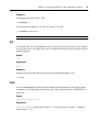
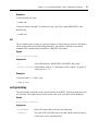
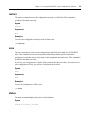
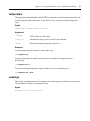
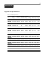
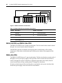
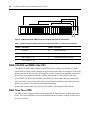
CYCLADES® PM IPDU
Installer/User Guide
FCC Warning Statement
The Cyclades PM IPDU has been tested and found to comply with the limits for Class A digital devices,
pursuant to Part 15 of the FCC rules. These limits are designed to provide reasonable protection against harmful
interference when the equipment is operated in a commercial environment. This equipment generates, uses, and
can radiate radio frequency energy and, if not installed and used in accordance with the Installation & Service
Manual, may cause harmful interference to radio communications. Operation of this equipment in a residential
area is likely to cause harmful interference in which case the user is required to correct the problem at his or her
own expense.
Canadian DOC Notice
The Cyclades PM IPDU does not exceed the Class A limits for radio noise emissions from digital apparatus set
out in the Radio Interference Regulations of the Canadian Department of Communications.
Le Cyclades PM n’émete pas de bruits radioélectriques dépassant les limites applicables aux appareils numériques de la classe A prescrites dans le règlement sur le brouillage radioélectrique edicté par le Ministère des
Communications du Canada.
Japanese Approvals
Safety and EMC Approvals and Markings
FCC, ICES-003, CE, C-tick, VCCI, CB, PSE, GOSTR
Safety certifications and EMC certifications for this product are obtained under one or more of the following
designations: CMN (Certification Model Number), MPN (Manufacturer’s Part Number) or Sales Level Model
designation. The designation that is referenced in the EMC and/or safety reports and certificates are printed on
the label applied to this product.
Cyclades® PM IPDU
Installer/Administrator/User Guide
Avocent, the Avocent logo, The Power of Being There, Cyclades and
DSR are registered trademarks of Avocent Corporation or its affiliates in
the U.S. and other countries. All other marks are the property of their
respective owners.
© 2010 Avocent Corporation. 590-667-501E
Instructions
This symbol is intended to alert the user to the presence of important operating and maintenance
(servicing) instructions in the literature accompanying the appliance.
Dangerous Voltage
This symbol is intended to alert the user to the presence of uninsulated dangerous voltage within the
product’s enclosure that may be of sufficient magnitude to constitute a risk of electric shock to persons.
Power On
This symbol indicates the principal on/off switch is in the on position.
Power Off
This symbol indicates the principal on/off switch is in the off position.
Protective Grounding Terminal
This symbol indicates a terminal which must be connected to earth ground prior to making any other
connections to the equipment.
Table of Contents
iii
T A B L E O F C ON T E N T S
Table of Contents
List of Figures ................................................................................................................ vii
List of Tables ................................................................................................................... ix
Chapter 1: Introduction ................................................................................................... 1
Features and Benefits ........................................................................................................................ 1
Alarms and monitoring ............................................................................................................... 1
Sequential power application ..................................................................................................... 1
Support for daisy chaining ......................................................................................................... 1
Integration with Avocent management products ........................................................................ 2
Hardware Configuration Options...................................................................................................... 2
Standalone configuration ........................................................................................................... 2
Daisy chained configuration....................................................................................................... 3
Integrated configuration............................................................................................................. 3
Chapter 2: Installation ..................................................................................................... 5
Getting Started ................................................................................................................................... 5
Supplied with the PM IPDU .............................................................................................................. 5
Modular input power cables for the PM IPDU .......................................................................... 5
Optional outlet cable package .................................................................................................... 5
Rack Mounting the PM IPDU............................................................................................................ 6
Installation environment............................................................................................................. 6
Daisy Chaining PM IPDUs ............................................................................................................... 9
Accessing the Console ....................................................................................................................... 9
Direct console access ................................................................................................................. 9
Console access through a management device ........................................................................ 10
Configuring the PM IPDU............................................................................................................... 10
Default configuration parameters ............................................................................................ 10
Initial configuration using the command prompt ..................................................................... 10
Resetting the admin password .................................................................................................. 11
Upgrading the PM IPDU firmware.......................................................................................... 12
Chapter 3: Accessing the PM IPDU via the Command Line Interface....................... 13
PM IPDU User Interface ................................................................................................................. 13
Daisy chained PM IPDUs in the login prompt......................................................................... 13
iv
Cyclades PM IPDU Installer/Administrator/User Guide
Logging in to the PM IPDU...................................................................................................... 13
Commands ....................................................................................................................................... 14
adduser............................................................................................................................................. 14
alarm ................................................................................................................................................ 14
assign ............................................................................................................................................... 15
buzzer ............................................................................................................................................... 16
current.............................................................................................................................................. 16
currentprotection ............................................................................................................................. 17
cycle ................................................................................................................................................. 18
dbsync .............................................................................................................................................. 19
deluser.............................................................................................................................................. 19
display .............................................................................................................................................. 19
exit.................................................................................................................................................... 21
factory_default ................................................................................................................................. 21
help................................................................................................................................................... 21
humidity ........................................................................................................................................... 22
hwocp ............................................................................................................................................... 23
id ...................................................................................................................................................... 23
interval ............................................................................................................................................. 24
list..................................................................................................................................................... 25
lock................................................................................................................................................... 25
name................................................................................................................................................. 26
off ..................................................................................................................................................... 26
on ..................................................................................................................................................... 27
outcycledelay ................................................................................................................................... 27
passwd.............................................................................................................................................. 28
reboot ............................................................................................................................................... 28
restore .............................................................................................................................................. 29
save .................................................................................................................................................. 29
status ................................................................................................................................................ 29
syslog ............................................................................................................................................... 30
temperature ...................................................................................................................................... 31
unassign ........................................................................................................................................... 31
unlock............................................................................................................................................... 32
upgrade ............................................................................................................................................ 32
Table of Contents
v
ver .................................................................................................................................................... 33
voltage.............................................................................................................................................. 34
whoami............................................................................................................................................. 34
Appendices..................................................................................................................... 35
Appendix A: Specifications .............................................................................................................. 35
Appendix B: Safety Instructions....................................................................................................... 38
Appendix C: Circuit Breakers.......................................................................................................... 42
Appendix D: Technical Support....................................................................................................... 48
vi
Cyclades PM IPDU Installer/Administrator/User Guide
List of Figures
vii
LIST OF FIGU RES
List of Figures
Figure 1.1: Standalone Configuration............................................................................................... 2
Figure 1.2: Daisy Chained PM IPDUs with an Avocent Management Device................................. 3
Figure 2.1: Rack Mount Bracket Installation on a PM IPDU........................................................... 6
Figure 2.2: A Sample PM IPDU (PM42 Shown)............................................................................... 8
Figure C.1: PM10-L30A IPDU Circuit Breakers .......................................................................... 43
Figure C.2: PM10i-L30A IPDU Circuit Breakers ......................................................................... 44
Figure C.3: PM20-L30A IPDU Circuit Breakers .......................................................................... 45
Figure C.4: PM20i-L30A IPDU, PM20i-32A IPDU and PM20i-32Au IPDU Circuit Breakers ... 46
viii
Cyclades PM IPDU Installer/Administrator/User Guide
List of Tables
ix
LIST OF TABLES
List of Tables
Table 1.1: Standalone Configuration Descriptions ........................................................................... 2
Table 2.1: PM IPDU Shipping Box Contents and Description ......................................................... 5
Table 2.2: PM IPDU Optimum Installation Environment................................................................. 6
Table 2.3: Cyclades PM42 IPDU Callout Descriptions.................................................................... 8
Table A.1: PM IPDU Specifications................................................................................................ 35
Table A.2: PM42 IPDU Specifications............................................................................................ 36
Table A.3: Pinouts for IN and OUT RS-232 Serial Ports................................................................ 36
Table C.5: Circuit Breaker Trip Time ............................................................................................. 47
Table C.6: PM42 IPDU Shutdown Time ......................................................................................... 47
x
Cyclades PM IPDU Installer/Administrator/User Guide
1
CHAPTER
1
Introduction
This installation, administration and user’s guide provides background information and procedures
for installing, configuring and maintaining the Cyclades® Power Management (PM) Intelligent
Power Distribution Unit (IPDU) family.
The Cyclades PM IPDU enables remote power control of servers and network gear. When used in
conjunction with DSR® switches or console servers, the PM IPDU delivers easier management
capabilities and faster problem solving by integrating console/KVM access and power control into
one single interface.
The following sections describe general features common to all PM IPDU models and point out
specific features of certain units.
Features and Benefits
Alarms and monitoring
The PM IPDU delivers accurate, real-time global current monitoring of all connected devices via
the user interface screen or locally through an LED digital display. Users have the ability to set a
current alarm threshold that, once exceeded, will cause the PM IPDU to sound an alarm or send a
notification message, or both.
Sequential power application
The PM IPDU incorporates a sequential power application feature that prevents all power outlet
receptacles from turning on at once, eliminating the potential of current surges that could render the
equipment inoperable. Together with the global current monitoring, the sequential power
application feature lets users safely install more equipment on existing power circuits without the
worry of current overloads.
Support for daisy chaining
The IPDU has a fixed number of power outlet receptacles, but with daisy chaining capabilities,
users may increase capacity by connecting the control interfaces of several PM IPDUs in a series.
2
Cyclades PM IPDU Installer/Administrator/User Guide
Integration with Avocent management products
The PM IPDU can be combined with an ACS console server or DSR KVM switch to provide
enhanced functionality. Please refer to the appropriate product documentation for more information
on how to use the PM IPDU with your specific implementation.
Hardware Configuration Options
The PM IPDU may be used in one of three hardware configurations:
•
Standalone – Managed independently of any other hardware device.
•
Daisy chained - Multiple PM IPDUs connected to one another and managed by one main
PM IPDU.
•
Integrated – Managed by a console server or a KVM switch.
Standalone configuration
In a standalone configuration, the PM IPDU operates independently of any other hardware. The
following graphic displays a PM IPDU with the console port connected to a computer running
terminal emulation.
1
2
6
3
5
4
Figure 1.1: Standalone Configuration
Table 1.1: Standalone Configuration Descriptions
Number
Description
Number Description
1
RJ-45 to DB-9F Adaptor (Optional)
4
Server
2
RJ-45 Cable
5
Switch
3
IN Port
6
Power Source
Chapter 1: Introduction
3
NOTE: The installation example displays the PM IPDU being connected with the RJ-45 to DB-9F adaptor that is
shipped with the product. If the unit you are connected to does not have a DB-9M COM port, you may use a USB
serial adaptor and connect to a USB port when possible.
Daisy chained configuration
In a daisy chained configuration, multiple PM IPDUs are connected to one another and managed by
a single main PM IPDU. The PMs are linked together with RJ-45 cables connected through the PM
IPDU’s IN and OUT ports. The following example shows three PM IPDUs operating in a daisy
chained environment. PM IPDU #1 is connected to the local workstation and is the “main”
PM IPDU.
Figure 1.2: Daisy Chained PM IPDUs with an Avocent Management Device
Integrated configuration
In an integrated configuration, the PM IPDU is configured to work in conjunction with an Avocent
management product.
A user connects to the PM IPDU by accessing the appropriate console port of the Avocent
management product. In this scenario, software configuration on and monitoring of the PM IPDU
is done through the Avocent management product and not on the PM IPDU itself. Visit
www.avocent.com for more information.
4
Cyclades PM IPDU Installer/Administrator/User Guide
Chapter 2: Installation
5
CHAPTER
Installation
2
Getting Started
Collect the following equipment prior to installing and configuring the PM IPDU in
standalone configuration:
•
One or more RJ-45 to RJ-45 straight-through cables
•
An RJ-45 to DB-9F straight-through adaptor
•
A PC running a terminal emulation program
Supplied with the PM IPDU
Table 2.1: PM IPDU Shipping Box Contents and Description
Description
Purpose
PM IPDU Quick Installation Guide (QIG)
Basic installation guide in printed format.
RJ-45 to RJ-45 7ft. straight through
CAT5 cable
Used for the following:
Along with an adaptor, to connect a terminal or PC to the IN port.
To connect to a Cyclades console or KVM management device.
To connect to another PM IPDU in a daisy chain.
RJ-45 to DB-9F straight-through adaptor
Along with an RJ-45 cable, used to connect a terminal or PC to a
PC’s COM port.
RJ-45 loopback connector
Used to gain temporary access to the PM IPDU.
PM IPDU to DSR switch cable adaptor
Used to connect a PM IPDU to an Avocent switch’s SPC port.
Mounting brackets and screws (2 spares)
for PM10 IPDU and PM10i IPDU
Use to mount the Cyclades PM10 IPDU and PM10i IPDU to a
rack or wall.
Modular input power cables for the PM IPDU
If your PM IPDU model does not have a fixed power input cable, it may ship with a modular cable.
Depending on your site’s location, the modular input power cables included in the box vary.
NOTE: The Cyclades PM 10i-32Au IPDU ships with an unterminated power cord. If necessary, contact Avocent
Technical Support for guidelines on approved power plug installation.
Optional outlet cable package
The following cable packages may be ordered separately for the IEC PM IPDU models:
6
Cyclades PM IPDU Installer/Administrator/User Guide
•
8-outlet cables (C13 female to C14 male)
•
10-outlet cables (C13 female to C14 male)
Rack Mounting the PM IPDU
You may mount the PM IPDU on a rack or wall or place it on a desktop or other flat surface. Two
brackets are supplied with six Phillips screws for attaching the brackets to the PM8i IPDU, the
PM10 IPDU and the PM10i IPDU for mounting.
If you are mounting the PM IPDU, obtain a Phillips screwdriver and appropriate nuts and bolts
before mounting the PM IPDU.
NOTE: When mounting a PM IPDU zero U model to a wall stud, securely mount it by using a #10 (4.8 mm or
0.19 in or 3/16 in) or larger screw or use a drywall fastener rated min. 25 lb. (11.34 kg).
The following graphic depicts the orientation of the brackets for front rack mounting a PM IPDU.
Figure 2.1: Rack Mount Bracket Installation on a PM IPDU
Installation environment
When installing the PM IPDU, ensure that the following environment specifications are met.
Table 2.2: PM IPDU Optimum Installation Environment
Environment Factor
Recommendation
Temperature
The manufacturer's maximum recommended ambient temperature for the
PM IPDU is 104 ºF (40 ºC).
Chapter 2: Installation
7
Table 2.2: PM IPDU Optimum Installation Environment (Continued)
Environment Factor
Recommendation
Elevated Operating Ambient
Temperature
If the PM IPDU is installed in a closed or multi-unit rack assembly, the
operating ambient temperature of the rack environment may be greater
than room ambient temperature. Therefore, consideration should be given
to installing the equipment in an environment compatible with the
manufacturer’s maximum rated ambient temperature. See above.
Reduced Air Flow
Installation of the equipment in a rack should be such that the amount of air
flow required for safe operation of the equipment is not compromised.
Mechanical Loading
Mounting of the equipment in the rack should be such that a hazardous
condition is not created due to uneven mechanical loading.
Circuit Overloading
Consideration should be given to the connection of the equipment to the
supply circuit and the effect that overloading of circuits might have on
overcurrent protection and supply wiring. Appropriate consideration of
equipment nameplate ratings should be used when addressing
this concern.
Reliable Grounding
Reliable grounding of rack-mounted equipment should be maintained.
Particular attention should be given to supply connections other than direct
connections to the branch circuit, such as power strips or extension cords.
NOTE: Install a PM IPDU 0U model in a location where there is an adjacent and accessible socket outlet.
CAUTION: The plug on the power cord of the PM IPDU is used as the disconnect device.
To mount the PM10 IPDU or PM10i IPDU:
1.
Using a Phillips screwdriver, attach the supplied brackets to the sides of the PM IPDU.
2.
Use the mounting hardware recommended for your rack to mount the PM IPDU.
8
Cyclades PM IPDU Installer/Administrator/User Guide
11
10
12
13
14
4
1
5
2 3
7
6
9
Figure 2.2: A Sample PM IPDU (PM42 Shown)
Table 2.3: Cyclades PM42 IPDU Callout Descriptions
Number/Letter
Description
1
Outlet, IEC320-C13, 14 each for bank XY, YZ and XZ
2
RS-232 (IN) Port
3
MULTI (OUT) Port
4
HWOCP Reset Button
5
Three digit LED displays the current on Phase X, Y and Z in sequence, or the voltage
across Phases X and Y, Y and Z, and X and Z in sequence
6
SCROLL button - manually toggles display when the display command is set to cycle
manually (see display on page 19)
7
LED indicates when Phase X current is displayed
8
LED indicates when Phase Y current is displayed
9
LED indicates when Phase Z current is displayed
10
Bank XY
11
Bank YZ
12
Bank XZ
13
HWOCP Indicator LED
14
L21-30P 208 VAC 30A Plug
8
Chapter 2: Installation
9
Daisy Chaining PM IPDUs
You may manage a maximum of 128 outlets by connecting multiple PM IPDUs to the main PM
IPDU device.
To daisy chain a PM IPDU:
This procedure assumes that a main PM IPDU is already connected to a workstation or
management appliance.
1.
Connect one end of an RJ-45 cable to the OUT port of the main PM IPDU, which is connected
to a workstation or management appliance.
2.
Connect the other end of the RJ-45 cable to the IN port of the secondary Cyclades PM IPDU.
3.
Repeat these steps until you have connected the desired number of PM IPDUs.
Accessing the Console
Users and administrators may access the PM IPDU either by making a direct console connection to
the PM IPDU’s IN port or by connecting the PM IPDU to an Avocent console or KVM switch
management device.
Direct console access
While using the PM IPDU device independently of other Avocent devices, local users may connect
directly to the system console port (the IN port) of the PM IPDU using the console cable with the
corresponding adaptor(s).
The system administrator must specify basic settings on the PM IPDU before users may connect to
and manage the unit and the connected devices. To perform necessary basic configuration, make a
direct connection to the PM IPDU by connecting a terminal or computer to the IN port.
To access the console:
Perform the following steps to connect a computer to the console port of the PM IPDU. This
procedure assumes that you know how to use a terminal emulation program.
1.
Connect an RJ-45 serial cable to the IN port on the PM IPDU.
2.
Connect the RJ-45 serial cable to a computer with a terminal emulation program using the RJ45 to DB-9F straight-through adaptor or a USB serial adaptor.
3.
Using a terminal emulation program, connect to the PM IPDU with the following settings:
ANSI emulation, 9600 bps, 8 bits, no parity, 1stop bit and no flow control.
When prompted, enter the username admin with the default password pm8.
If this is a first-time installation, see Initial configuration using the command prompt on page 10
for instructions on changing the default password, adding users and assigning outlets to users.
10
Cyclades PM IPDU Installer/Administrator/User Guide
Console access through a management device
By integrating the PM IPDU device with an Avocent console or KVM switch management device
such as DSView 3 software or Cyclades ACS, remote users may access the PM IPDU's console
port through a menu-driven interface. Using Telnet or SSH through the console server, type the
power management hotkey (Ctrl+P by default) to activate a power management menu. Please refer
to the appropriate product documentation for more information.
To connect a PM IPDU to an Avocent DSR switch:
Use the included RJ-45 cable adaptor to connect a PM IPDU to an Avocent DSR switch.
1.
Plug the male end of the adaptor into the DSR switch’s SPC port.
2.
Plug one end of a straightthrough CAT 5 cable into the female end of the adaptor.
3.
Plug the other end of the CAT 5 cable into the PM IPDU’s IN port.
Configuring the PM IPDU
The PM IPDU may be configured by any one of two methods:
•
Command Prompt - Full configuration capabilities
•
Browser or text based menu - Available only when the PM IPDU is connected to a
management device
For information about integrated use with an Avocent management device visit www.avocent.com
or refer to the documentation relevant to that product family.
Default configuration parameters
The PM IPDU’s default configuration is as follows:
•
User is admin.
•
Admin user’s password is pm8.
•
All outlets are un-named.
•
All outlets are unassigned to user.
•
All outlets are turned on.
•
All outlets are unlocked.
Initial configuration using the command prompt
To change the default admin password (if pm8 is in use):
1.
Log in to the PM IPDU using the default username admin and password pm8.
2.
Enter the passwd command.
3.
Enter a new password when prompted.
Chapter 2: Installation
11
To create users with the adduser command:
1.
Log in to the PM IPDU.
2.
Enter the adduser command followed by the new username.
3.
Enter the password when prompted.
To assign outlets to users with the assign command:
1.
Log in to the PM IPDU.
2.
Enter the assign command followed by the outlet number(s) and username.
Example:
pm>assign 2 jane
Outlet 2 assigned to jane.
To name the outlets with the name command:
1.
Log in to the PM IPDU.
2.
Enter the name command followed by the outlet number and desired name of the outlet.
Example:
pm>name 2 chispa
2: Outlet now named chispa
To save the configuration with the save command:
1.
Log in to the PM IPDU.
2.
Enter the save command to save the configuration.
Resetting the admin password
In the event the administrator wants to reset the password for the PM IPDU (for example, if the
administrator forgets the admin password), then the loopback connector that is shipped with the PM
IPDU may be used for temporary access to the PM IPDU.
To reset the admin password using the loopback connector:
1.
If you are not logged out, log out by entering exit. (You must be at the login prompt for this
to work.)
2.
Connect the loopback connector shipped with the PM IPDU to the OUT port.
3.
Check the display. If you are watching the PM IPDU's console output, your status will
be reported.
4.
After one minute, you may remove the loopback connector. The password for the user admin is
reset to the default (pm8), and you should be able to log into the PM IPDU using the default
12
Cyclades PM IPDU Installer/Administrator/User Guide
username/password. For maximum security, the admin password should be changed as soon
as possible.
Upgrading the PM IPDU firmware
The upgrade procedure described here is only valid for units that are currently running firmware
versions 1.3.0 or greater. If your PM IPDU is running an older firmware version, please follow the
instructions in the manual that corresponds to the firmware currently installed on the PM IPDU.
To upgrade PM IPDU firmware:
1.
Download the new PM IPDU firmware from the Avocent web site.
2.
Using terminal emulation software, log into the PM IPDU as admin and type in the command:
pm>upgrade <IPDU#>
The <IPDU#> is the number of the IPDU to which you want to upgrade the firmware. If you
have only one PM IPDU, type upgrade 1. If you have, for instance, three units in a daisy
chain, type upgrade 3 or upgrade 2 depending on which unit you want to upgrade.
NOTE: If you have a daisy chain and you want to upgrade all units, you should start from the last unit and work
your way towards the first.
3.
At the boot loader menu, select option 1 to upgrade the firmware.
The boot loader erases the firmware currently in the unit and asks you to upload the
new firmware.
4.
Use your terminal emulator program to upload the PM IPDU firmware file to the PM IPDU
using the Xmodem protocol.
For information about using a different terminal emulator, please refer to the documentation
provided by the manufacturer on how to transfer files using the Xmodem protocol.
When the file transfer is complete, the PM IPDU console displays the login prompt. You may log
into the PM IPDU and perform actions as usual.
If the file transfer fails, an error message appears on the PM IPDU console, and the boot loader
menu is displayed again so you may redo the firmware upgrade process.
In this case, select option 1 from the menu and repeat the firmware upload procedure. If the
problem persists, contact Avocent Technical Support for assistance.
13
CHAPTER
3
Accessing the PM IPDU via the
Command Line Interface
When using the PM IPDU independently of other Cyclades products, users and administrators may
access the PM IPDU command line interface through a terminal emulation program.
PM IPDU User Interface
You may access the PM IPDU user interface by following the instructions provided in Direct
console access on page 9. Depending on the PM IPDU’s boot status, either the Boot Menu or the
Login Prompt will appear.
On the Boot Menu, you may enter 2 (or just wait approximately 12 seconds) to activate the
Login Prompt.
Daisy chained PM IPDUs in the login prompt
Number of PM IPDUs
If no PM IPDUs are daisy chained, the [PM]: IPDU: line appears only once, and the value is 1.
If there are any PM IPDUs daisy chained to the first PM IPDU, the [PM]: IPDU: line appears once
for each PM IPDU in the chain. For each PM IPDU, the value is incremented by 1. The final
appearance of the [PM]: IPDU: line will show the total number of PM IPDUs in the daisy chain.
Number of PM IPDU outlets
If no PM IPDUs are daisy chained, the [PM]: OUT: line appears only once, and the value is equal
to the number of outlets on the PM IPDU.
If there are any PM IPDUs daisy chained to the first PM IPDU, the [PM]: OUT: line appears once
for each PM IPDU in the chain. For each PM IPDU, the value shows the cumulative total of outlets
until the total number of outlets for the entire chain is displayed.
Logging in to the PM IPDU
When prompted, enter your username and password.
NOTE: If there are daisy chained PM IPDUs, you will need to press Enter after the final [PM]: OUT: line appears.
14
Cyclades PM IPDU Installer/Administrator/User Guide
After a successful login, the PM IPDU command prompt appears after which you may use any of
the commands described in this chapter.
Commands
NOTE: When a range of outlets is used in a command and the range spans more than one PM IPDU in a daisy
chain, the range of outlets must not be specified by name. The range of outlets may only be specified by number
in this situation.
adduser
The adduser command adds one username to the internal database. A maximum of eight characters
(not case sensitive) is allowed, and a maximum of eight individual users is allowed. This command
is available to the admin user only.
Syntax
adduser <user>
Arguments
<user> username
Examples
To add a user, enter:
pm>adduser popper
alarm
The alarm command sets the current threshold for alarm to <threshold> on IPDU #<ipdu number>.
<threshold> should be between 2A and the maximum current. Alarm threshold can be set for each
phase or segment. The limit in each segment is half of the maximum current of the PM. When
issued without threshold it shows the current alarm settings.
Syntax
alarm [<ipdu number or ID>]
For PM42 IPDUs:
alarm [<ipdu number or ID> [<threshold> X|Y|Z]]
For 30A IPDUs:
alarm [<ipdu number or ID> [<threshold> A|B]]
For other IPDU models:
alarm [<ipdu number or ID> [<threshold>]]
Chapter 3: Accessing the PM IPDU via the Command Line Interface
15
Arguments
<IPDU# or ID>
IPDU number in a daisy chain or identification string set by the id
command
<threshold>
Value of the threshold current above which IPDU enters alarm condition.
X|Y|Z
Phase identification for three-phase model (PM42 IPDU) for which the
alarm threshold will be set. If no phase is given, the threshold will be set
to the same value for all phases
A|B
Segment identification for two-segment models (30/32A IPDU). If no
letter is given, the threshold for the total IPDU current will be set
Examples
To set the threshold on PM IPDU number one to 5.6A, enter:
pm>alarm 1 5.6
To set the threshold on PM IPDU number two phase Y to 5.6A, enter:
pm>alarm 2 5.6 Y
To read the threshold, enter:
pm>alarm
To set the threshold on segment A of a two-segment IPDU number 3-4.6A, enter:
pm>alarm 3 4.6 A
assign
The assign command assigns management of an outlet to a given user. This command is available
to the admin user only.
Syntax
assign <outlet_number> <user>
16
Cyclades PM IPDU Installer/Administrator/User Guide
Arguments
<outlet_number>
Outlet number, such as “5”, outlet name such as “sunfire”, or group of
outlets such as “1, 3-5”
<user>
Desired username
Examples
To assign outlet 4, 6, 7 and 8 to user tess, enter:
pm>assign 4, 6-8 tess
buzzer
The buzzer command displays or changes the buzzer notification status. When set to “on”, a buzzer
sounds when the current exceeds the threshold. This command is available to the admin user only.
Syntax
buzzer <on|off|status>
Arguments
on
Enables buzzer
off
Disables buzzer
status
Displays buzzer status
Examples
To get the current status of the buzzer notification, enter:
pm>buzzer status
To turn buzzer notification on or off, enter:
pm>buzzer on
pm>buzzer off
current
Displays the current and the maximum recorded current in Amps in a unit if the IPDU
identification is provided, or in all units if it is not provided. The reset option clears the maximum
recorded current.
Syntax
current reset [<ipdu number or ID>]
Chapter 3: Accessing the PM IPDU via the Command Line Interface
17
For PM42 IPDUs:
current [<ipdu number or ID> X|Y|Z]
For 30A IPDUs:
current [<ipdu number or ID> A|B]
For other IPDU models:
current [<ipdu number or ID>]
Arguments
<IPDU# or ID>
IPDU number in the daisy chain or identification string set previously set
by the id command
X|Y|Z
Phase identification for three-phase model (PM42 IPDU)
reset
Clears the saved peak current value
A|B
Segment identification for two-segment models (30/32A IPDU)
Examples
To get the current status for all units, enter:
pm>current
To get the current status for a specific unit, enter:
pm>current 2
To reset maximum current drawn, enter:
pm>current reset
currentprotection
The currentprotection command turns the over current protection feature on or off. The overcurrent
protection does not allow an outlet to be turned on if the current drawn by the unit, phase or
segment is greater than the current threshold configured for each of them using the command
“alarm.” This command may also be used to display the current protection status and is available to
the admin user only.
Syntax
currentprotection <on|off|status>
18
Cyclades PM IPDU Installer/Administrator/User Guide
Arguments
on
Enables over current protection
off
Disables over current protection
status
Displays the current protection status
Examples
To display current protection status for all units, enter:
pm>currentprotection status
To enable current protection status for all units, enter:
pm>currentprotection ON
To disable current protection status for all units, enter:
pm>currentprotection off
NOTE: Current protection commands affect all IPDUs in the daisy chain and all phases of the PM42 IPDU.
cycle
The cycle command power cycles an outlet or group of outlets. You may use the outlet number or
the outlet name (see command name for details).
Syntax
cycle all|<outlet_string>
Arguments
all
Cycles all outlets in the PM IPDU or PM IPDU daisy chain
<outlet_string>
Outlet number, such as “5”, outlet name such as “sunfire”, or group
of outlets such as “1, 3-5”
Examples
To cycle outlet 3, enter:
pm>cycle 3
To cycle outlets 2, 3, 5, 6 and 7, enter:
pm>cycle 2, 3, 5-7
Chapter 3: Accessing the PM IPDU via the Command Line Interface
19
dbsync
The dbsync command synchronizes the user database for all PM IPDUs in the chain. This
command is available to the admin user only.
Syntax
dbsync
Arguments
none
Examples
To synchronize the user database for all PM IPDUs in the chain, enter:
pm>dbsync
deluser
The deluser command deletes one username from the internal database. This command is available
to the admin user only.
Syntax
deluser <user>
Arguments
<user> Desired username
Examples
To delete the user “rog”, enter:
pm>deluser rog
display
Sets Display mode. <0|180> sets up the display orientation. For PM42 IPDUs, it can show current
(I) or voltage (V), and it cycles each <cycle time> seconds. In 30A IPDUs it may show 3 values;
current in segment [A], in segment [b] and the consolidated [C] when <cycle time> is defined. It
displays the letter [A] for .5 sec followed by the value of the current in seg.A, then the letter [b] for
.5 sec followed by the value of the current in seg.B, and then the letter [C] followed by the total
current in the unit.
If <cycle time> is not defined, it will either cycle manually (three-phase models) or display only
total current (two-segment models).
20
Cyclades PM IPDU Installer/Administrator/User Guide
NOTE: The decimal point will be at the top of the display when the display command is issued with 180-degree
rotation on PM IPDUs with seven-segment displays. The PM42 IPDU has dot matrix display which will display
values with the decimal point correctly positioned in inverted mode.
Syntax
For PM42 IPDUs:
display [<ipdu number or ID> [<0|180> <I|V>[ <cycle time>]]]
For 30A IPDUs:
display [<ipdu number or ID> [<0|180>[ <cycle time>]]]
For other IPDU models:
display [<ipdu number or ID> [<0|180>]]
Arguments
no argument
Show display status of all IPDUs in the daisy chain
<IPDU# or ID>
IPDU number or ID in the daisy chain or identification string previously
set by the id command
<IPDU_ID>
Identification string previously set by the id command
0
Normal mode (default)
0|180
Set the orientation of the display: 0 (zero) is the default normal mode, 180
degrees is the inverted mode
Examples
To set the display of IPDU #2 to inverted mode, enter:
pm>display 2 180
To set the display of IPDU #1 to normal mode, enter:
pm>display 1 0
To set the display of IPDU #3 (PM42) to automatically show the current of each phase every two
seconds, enter:
pm>display 3 Iauto 2
To view the display status, enter:
pm>display
Chapter 3: Accessing the PM IPDU via the Command Line Interface
21
exit
The exit command exits the session.
Syntax
exit
Arguments
none
Examples
To exit the current session, enter:
pm>exit
factory_default
The factory_default command resets the unit to its factory configuration. When used with a daisy
chain, and no argument is given, this command resets all units in the chain. This command is
available to the admin user only.
Syntax
factory_default [<IPDU#>|<IPDU_ID>]
Arguments
no argument
Resets all PM IPDUs in the daisy chain to factory default
<IPDU#>
Number of the PM IPDU in the chain
<IPDU_ID>
Identification string previously set by the id command
Examples
To reset the factory default, enter:
pm>factory_default 1
help
The help command displays the system help message for all commands or for a single command
when specified.
NOTE: When the admin user is logged in, the help command displays all commands. When a regular user is
logged in, the help command displays only the regular user commands.
22
Cyclades PM IPDU Installer/Administrator/User Guide
Syntax
<command> help
Arguments
<command> Any available command
Examples
To view the system help message for a specific command, enter the command followed by help.
pm>syslog help
To view the system help message for all commands, enter:
pm>help
humidity
The humidity command displays the PM IPDU’s surrounding humidity and the maximum humidity
the IPDU has registered (humidity peak). It may also be used to clear the saved peak
humidity value.
Syntax
humidity [<IPDU#>|<IPDU_ID>]|reset
Arguments
<IPDU#>
IPDU number in a daisy chain
<IPDU_ID>
Identification string previously set by the id command
reset
Resets the maximum humidity registered
Examples
To get the humidity for all units in a daisy chain, enter:
pm>humidity
To get the humidity for specific unit, provide the unit number as an argument, enter:
pm>humidity 2
To reset the maximum humidity registered, enter:
pm>humidity reset
Chapter 3: Accessing the PM IPDU via the Command Line Interface
23
hwocp
The hwocp command without argument checks the status of the hardware overcurrent protection.
When an overload of the PM IPDU with hwocp occurs, the hwocp will trip, similar to a
conventional circuit breaker, and all outlets will be shut off. To reset the hwocp, remove the
overload and issue the hwocp command with the “reset” argument. If no IPDU is specified, the
“reset” argument resets all PM IPDUs in the daisy chain. This command is available to the admin
user only.
Syntax
hwocp [<IPDU#>|<IPDU_ID> [reset]]
Arguments
<IPDU#>
IPDU number in a daisy chain
<IPDU_ID>
Identification string previously set by the id command
reset
Turns overcurrent protection off (normal operation)
Examples
To check the hardware overcurrent status of IPDU #1, enter:
pm>hwocp 1
To reset the hardware overcurrent protection, enter:
pm>hwocp 1 reset
id
The id command sets or displays the ID of a PM IPDU. A maximum of 16 characters (not case
sensitive) is allowed. Spaces, numbers and special characters are allowed. This command is
available to the administrator user only.
This command works in a daisy chain.
Syntax
id [<IPDU#>] [<IPDU_ID>]
-orid [<IPDU_ID>] [<IPDU_ID>]
-orid
24
Cyclades PM IPDU Installer/Administrator/User Guide
Arguments
<IPDU#>
IPDU number in a daisy chain
<IPDU_ID>
Identification string previously set by the id command
no argument
Displays the IDs of all PM IPDUs in the daisy chain
If <IPDU_ID> follows <IPDU#>, or if the <IPDU_ID> parameter is typed twice, the latest entry
of the <IPDU_ID> parameter updates the ID string.
Examples
To set the ID of PM IPDU 1 R&D, enter:
pm>id 1 R&D
To display the ID of PM IPDU 2, enter:
pm>id 2
To rename an ID to “sammy,” using an existing ID “QA,” enter:
pm>id QA sammy
To display the IDs of all PM IPDUs in the daisy chain, enter:
pm>id
interval
The interval command configures the time interval (in seconds) to turn on power for each outlet in
the system. This command is available to the admin user only.
Syntax
interval <outlet_number> <duration>
Arguments
<duration>
Sets the interval to turn on power to outlets. Valid intervals are
from 0 to 100. Default value is 0.5
NOTE: When this value is set to 0.0, there is still an interval of approximately 0.1 seconds between outlets to
receive power.
<outlet_number>
Outlet number, such as “5”, outlet name such as “sunfire”, or group
of outlets such as “1, 3-5”
Chapter 3: Accessing the PM IPDU via the Command Line Interface
25
Examples
To display the interval of outlet 1, enter:
pm>interval 1
To set the interval of outlets 2, 4, 5, and 6 to a value of 2.4, enter:
pm>interval 2,4-6 2.4
NOTE: The PM42 IPDU will not accept entries with decimal places.
list
For the admin user, the list command lists all users that have been created and the outlets assigned
to each of those users. For regular users, the list command lists only the outlets assigned to the user
currently logged in.
Syntax
list
Arguments
none
Examples
As admin, to list usernames and associated outlets in the internal database, enter:
pm>list
lock
The lock command locks an outlet or group of outlets in their current state. The response to this
command is a list of status lines, one per power port. This command works on all PM IPDUs in a
daisy chain.
Syntax
lock all|<outlet_string>
Arguments
<outlet_string> Outlet number, such as “5”, outlet name such as “sunfire”, or group of
outlets such as “1, 3-5”
26
Cyclades PM IPDU Installer/Administrator/User Guide
Examples
To lock outlets 1, 2 and 6, enter:
pm>lock 1,2,6
name
The name command lists the outlet number <outlet#> as name <name>. The name command is
limited to 16 characters, cannot start with a number and commas (,) are not allowed. This command
is available to the administrator user only.
Syntax
name <outlet_number> <name>
Arguments
<outlet number> Outlet number, such as “5”
<name>
Desired outlet name
Examples
To name outlet 4 as nowhere, enter:
pm>name 4 nowhere
off
The off command turns an outlet or group of outlets off. This command works on outlets in a PM
IPDU daisy chain.
Syntax
off all|<outlet_string>
Arguments
all
Turns off all outlets in the PM IPDU or PM IPDU daisy chain
<outlet_string> Outlet number, such as “5”, outlet name such as “sunfire”, or group of
outlets such as “1, 3-5”
CAUTION: The “all” argument will turn off all outlets in a PM IPDU or PM IPDU daisy chain.
Chapter 3: Accessing the PM IPDU via the Command Line Interface
27
Examples
To turn all outlets off, enter:
pm>off all
To turn off outlets 2 through 7 (or all outlets except 1 and 10 in a single PM10 IPDU), enter
the following.
pm>off 2-9
on
The on command turns an outlet or a group of outlets on. If more than one outlet is selected there
will be an interval between outlets being powered on. The interval is defined by the interval
command. This command works on outlets in a PM IPDU daisy chain.
Syntax
on all|<outlet_string>
Arguments
all
Turns off all outlets in the PM IPDU or PM IPDU daisy chain
<outlet_string> Outlet number, such as “5”, outlet name such as “sunfire”, or group of
outlets such as “1, 3-5”
Examples
To turn on outlets 1, 3, 4 and 5, type:
pm>on 1, 3-5
outcycledelay
The outcycledelay command sets the cycle delay time for the IPDU. Valid cycle delay times are 1
to 60 seconds. If no argument is given, the current value of the cycle delay will be displayed.
Syntax
outcycledelay [<delay>]
Arguments
No argument
Shows the current value set for the cycle delay time
[<delay>]
The value of the cycle delay time in seconds, which can be any integer
value from 1 to 60; no decimal values
28
Cyclades PM IPDU Installer/Administrator/User Guide
passwd
The passwd command sets a password. Regular users may change or set their own password only.
The administrator may change his or her own password or any regular user’s password.
Syntax
passwd <user_name>
Arguments
<user_name>
Name of the user whose password is being changed
no argument
To change the current user’s password
Examples
To change the password for user alpha, when logged in as admin, enter:
pm>passwd alpha
Passwords may be set to null, which indicates that no password is needed.
reboot
The reboot command reboots a PM IPDU. You may reboot a specific unit by issuing the reboot
command followed by the unit’s logical number or the unit’s ID. Issuing the reboot command
without a parameter reboots the first unit in a chain, not all the units in a chain. This command is
available to the admin user only.
Syntax
reboot [<IPDU#>|<IPDU_ID>]
Arguments
<IPDU#>
IPDU number in a daisy chain
<IPDU_ID>
Identification string previously set by the id command
Examples
To reboot the first unit of the chain, or to reboot the unit in standalone mode, enter:
pm>reboot
To reboot the a specific IPDU in the chain (IPDU 2 shown), enter:
pm>reboot 2
Chapter 3: Accessing the PM IPDU via the Command Line Interface
29
restore
The restore command restores the configuration currently saved in Flash. This command is
available to the admin user only.
Syntax
restore
Arguments
N/A
Examples
To restore the configuration currently saved in Flash, enter:
pm>restore
save
The save command saves the current configuration in the Flash device built in to all PM IPDU
units. This command saves the username/password database and the specific information
pertaining to each outlet such as outlet name, outlet assignments and outlet state. This command is
available to the admin user only.
If you save your configuration to Flash it will be restored after the next reboot. If you do not save
your configuration to Flash, you will lose it all after the next reboot.
Syntax
save
Arguments
none
Examples
To save the configuration to Flash, enter:
pm>save
status
The status command displays the status of selected outlets.
Syntax
status all|<outlet_string>
30
Cyclades PM IPDU Installer/Administrator/User Guide
Arguments
<outlet_string> Outlet number, such as “5”, outlet name such as “sunfire”, or group of
outlets such as “1, 3-5”
all
Displays the status of all outlets in a PM IPDU or PM IPDU daisy chain
Examples
To display the status of outlet 1, enter:
pm>status 1
To display the status of all outlets, enter:
pm>status all
syslog
The syslog command displays or changes the syslog notification status. This command is available
to the admin user only.
Syntax
syslog on|off|status
Arguments
on
Enables message to be displayed in the console when there is an over
current situation
off
Disables the message notification
status
Displays the current syslog status of all PM IPDUs on the daisy chain
no argument
Same as status
Examples
To get the current status of the syslog notification, enter:
pm>syslog
To turn on and off the syslog notification, enter as necessary:
pm>syslog on
pm>syslog off
Chapter 3: Accessing the PM IPDU via the Command Line Interface
31
temperature
The temperature command displays the PM IPDU’s temperature and the maximum temperature the
unit has registered (temperature peak). It may also be used to clear the saved peak temperature
value.
Syntax
temperature [<IPDU#>|<IPDU_ID>]|reset
Arguments
<IPDU#>
IPDU number in a daisy chain
<IPDU_ID>
Identification string previously set by the id command
reset
Resets the maximum temperature registered
Examples
To get the temperature for all units in a daisy chain, enter:
pm>temperature
To get the temperature for specific unit, provide the unit number as an argument, enter
the following.
pm>temperature 2
To reset the maximum temperature registered and use reset as an argument, enter:
pm>temperature reset
unassign
The unassign command removes the assignment of an outlet or group of outlets from a given user.
This command is available to the admin user only.
Syntax
unassign <outlet_string> <user>
32
Cyclades PM IPDU Installer/Administrator/User Guide
Arguments
<outlet_string> Outlet number, such as “5”, outlet name such as “sunfire”, or group
of outlets such as “1, 3-5”
<user>
Desired username
Examples
To unassign outlet 2 and 4 from user diderot, enter:
pm>unassign 2,4 diderot
unlock
The unlock command unlocks an outlet or group of outlets in the current state. The response to this
command is a list of status lines, one per power port.
Syntax
unlock all|<outlet_string>
Arguments
<outlet_string>
Outlet number, such as “5”, outlet name such as “sunfire”, or group of
outlets such as “1, 3-5”
all
Unlocks all outlets in the PM IPDU or PM IPDU daisy chain
Examples
To unlock outlets 2, 3, 4 and 8, enter:
pm>unlock 2-4,8
upgrade
The upgrade command is available only to the administrator. You may either upgrade or boot
the firmware.
NOTE: For details on upgrading using the upgrade command or using the reboot command, see Upgrading the
PM IPDU firmware on page 12.
Syntax
upgrade <IPDU#>|<IPDU_ID>
Chapter 3: Accessing the PM IPDU via the Command Line Interface
33
Arguments
<IPDU#>
IPDU number in a daisy chain
<IPDU_ID>
Identification string previously set by the id command
If you wish to upgrade more than one IPDU, it is recommended that you upgrade the most remote
IPDU first.
Examples
To upgrade IPDU 1, type:
pm>upgrade 1
ver
The ver command shows the current software version and hardware model information of the
selected PM IPDU.
Syntax
ver [<IPDU#>|<IPDU_ID>]
-orver
Arguments
<IPDU#>
IPDU number in a daisy chain
<IPDU_ID>
Identification string previously set by the id command
no argument
Displays version information for the PM IPDU and for all PM IPDUs in a
daisy chain
Examples
To view the current software version of all IPDUs in a daisy chain, enter:
pm>ver
NOTE: If an IPDU has an id assigned to it, the ver command displays the word “id” followed by the name of the
IPDU and the model number of the PM IPDU.
To get this information for a specific unit, provide the unit number as an argument.
pm>ver 2
34
Cyclades PM IPDU Installer/Administrator/User Guide
voltage
The voltage command shows the true RMS voltage between two phases.
Syntax
voltage [<IPDU#>|<IPDU_ID> [AB|AC|BC]]
Arguments
<IPDU#>
IPDU number in a daisy chain
<IPDU_ID>
Identification string previously set by the id command
XY|YZ|XZ
Phases to select
no argument
Displays the RMS voltage on all units if voltage sensors are available
Examples
To view the RMS voltage on a PM42 IPDU across phases X and Y, enter:
pm>voltage 1 XY
whoami
The whoami command shows the username of the user currently logged in.
Syntax
whoami
Arguments
none
Examples
To view the current username, enter:
pm>whoami
35
APP ENDICE S
Appendices
Appendix A: Specifications
Table A.1: PM IPDU Specifications
Unit
Input
Voltage
Max Output Max Output Operating
Current
Each Outlet Temp
Weight
PM10-15A
100-125 VAC 15A (12A)
15A (12A)
10-50 ºC
PM10-20A,
PM10-L20A
100-125 VAC 20A (16A)
15A (12A)
PM10-L30A
100-125 VAC 30A (24A)
PM10i-10A
Width
Depth
Height
3.64 kg
17 in
8 in
1.75 in
10-50 ºC
3.64 kg
17 in
8 in
1.75 in
15A (12A)
10-50 ºC
3.64 kg
17 in
8 in
1.75 in
100-240 VAC 10A
10A
10-50 ºC
3.64 kg
17 in
8 in
1.75 in
PM10i-15A
100-240 VAC 15A (12A)
10A (8A)
10-50 ºC
3.64 kg
17 in
8 in
1.75 in
PM10i-16A
100-240 VAC 16A
10A
10-50 ºC
3.64 kg
17 in
8 in
1.75 in
PM10i-20A
100-240 VAC 20A (16A)
10A (8A)
10-50 ºC
3.64 kg
17 in
8 in
1.75 in
PM10i-32A,
PM10i-32Au
100-240 VAC 32A
10A
0-50 ºC
5.45 kg
17 in
11.5 in
1.75 in
PM10i-L30A
100-240 VAC 30A (24A)
10A (8A)
0-50 ºC
5.45 kg
17 in
11.5 in
1.75 in
PM20-20A,
PM20-L20A
100-125 VAC 20A (16A)
15A (12A)
10-50 ºC
7.73 kg
1.8 in
2.2 in
66 in
PM20-L30A
100-125 VAC 30A (24A)
15A (12A)
10-50 ºC
7.73 kg
1.8 in
2.2 in
66 in
PM20i-16A
100-240 VAC 16A
10A
0-50 ºC
7.73 kg
2 in
2.8 in
66 in
PM20i-20A,
PM20i-L20A
100-240 VAC 20A (16A)
10A (8A)
0-50 ºC
7.73 kg
2 in
2.8 in
66 in
PM20i-L30A
100-240 VAC 30A (24A)
10A (8A)
0-50 ºC
7.73 kg
2 in
2.8 in
66 in
PM20i-32A
100-240 VAC 32A
10A
10-50 ºC
7.73 kg
2 in
2.8 in
66 in
NOTE: The recommended maximum operating temperature for all models is 40 ºC.
36
Cyclades PM IPDU Installer/Administrator/User Guide
Power Cables
Some PM models have an unterminated power cable. The color of the wires follows the standard
color code: yellow/green is ground, blue is neutral and brown is live.
Table A.2: PM42 IPDU Specifications
Characteristics
Electrical
Input Voltage
Three phases, phase to phase 208 VAC
Max Input Current
24A
Max Output Current Total
16A on any single bank (XY, YZ or XZ)
-or13.8A evenly distributed on each bank (XY, YZ or XZ)
NOTE: Maximum allowed current in any bank is limited to 16A
although the maximum of 24A input current per phase must not be
exceeded. If equal loads are provided to all banks then, in order to
have this maximum input current of 24A, the maximum allowed
current per bank will have to be decreased to 13.8A.
Max Output Current Each Outlet
42 - IEC320-C13: 12A at 208 VAC (42 places)
Environmental
Recommended Maximum Operating
Temperature
40 ºC
Maximum Operating Temperature
50 ºC
Mechanical
Weight
10.89 kg
Physical Dimensions (W x D x H)
2.2 x 2.5 x 72.0 in
Interface Pinouts
Table A.3: Pinouts for IN and OUT RS-232 Serial Ports
Signal
Name/Function
I/O
IN Pin
OUT Pin
RTS
Request to Send
(O)
5
1
DTR
Data Terminal Ready
(O)
7
2
TxD
Transmit Data
(O)
6
3
Appendices
Table A.3: Pinouts for IN and OUT RS-232 Serial Ports (Continued)
Signal
Name/Function
I/O
IN Pin
OUT Pin
Gnd
Ground
N/A
4
4
CTS
Clear to Send
(I)
1
5
RxD
Receive Data
(I)
3
6
DCD
Data Carrier Detect
(I)
2
7
DSR
Data Set Ready
(I)
8
8
37
38
Cyclades PM IPDU Installer/Administrator/User Guide
Appendix B: Safety Instructions
Follow the safety precautions in this document when installing and operating the PM IPDU.
Safety Instructions
Read all the following safety guidelines to protect yourself and your Cyclades PM.
DANGER! All outlets of the PM IPDU output high voltage. Necessary precautions should be taken.
DANGER! To help prevent electric shock, plug the PM IPDU into a properly grounded power source. The power
cord is equipped with a three-prong plug to help ensure proper grounding. Do not use adaptor plugs or remove
the grounding prong from the cable. Do not use extension cords with the PM IPDU.
DANGER! Do not push any objects through the openings of the PM IPDU. Doing so may cause fire or electric
shock by shorting out interior components.
DANGER! There is a possibility of severe electrical shock from either the live or neutral side of any of the power
outlets or their wiring, even if one of the circuit breakers is disabled.
IMPORTANT: PM IPDU is intended for enterprise and indoor use only.
IMPORTANT: To help protect the PM IPDU from electrical power fluctuations, use a surge suppressor, line
conditioner, or uninterruptible power supply.
IMPORTANT: Be sure that nothing rests on the cables of the PM IPDU and that they are not located where they
may be stepped on or tripped over.
IMPORTANT: Do not spill food or liquids on the PM IPDU. If it gets wet, disconnect the power immediately and
contact Avocent.
IMPORTANT: Keep your PM IPDU away from heat sources.
Sicherheitsanweisungen
Bitte lesen und befolgen Sie diese Sicherheitsrichtlinien um sich und Ihren PM IPDU vor Schäden
zu bewahren.
GEFAHR! Alle Ausgänge des PM IPDU führen Hochspannung. Bitte die erforderlichen Vorsichtsmaßnahmen
einhalten.
GEFAHR! Um elektrische Stromschläge zu vermeiden, verbinden Sie bitte das Eingangskabel des PM IPDU mit
einer ausreichend geerdeten Stromversorgung. Das Netzkabel ist mit drei Leitungen versehen um korrekte
Erdung zu ermöglichen. Bitte benutzen Sie keine Adapterstecker und entfernen Sie nicht die Erdungsleitung.
Bitte verwenden Sie keine Verlängerungskabel.
GEFAHR! Bitte führen Sie keine Gegenstände in die Öffnungen des PM IPDU ein. Dies könnte zu Bränden oder
elektrischen Schock durch Kurzschluss der internen Komponenten führen.
Appendices
39
GEFAHR! Auch nach Öffnung einer der beiden Sicherungen kann das Gerät noch unter Spannung über die
Phasen- oder Nullleiterzufuhr stehen.
Wichtig: Der PM IPDU ist für den Unternehmenseinsatz und den Gebrauch innerhalb von abgeschlossenen
Gebäuden vorgesehen.
Wichtig: Um den PM IPDU vor elektrischen Spannungsschwankungen zu schützen empfehlen wir den Einsatz
von Überspannungsreglern, Spannungsglättern oder USVs.
Wichtig: Bitte stellen Sie sicher, daß keine Gegenstände auf den Kabeln des PM IPDU liegen und die Kabel so
geführt sind, daß niemand darauf treten oder darüber stolpern kann.
Wichtig: Bitte schütten Sie keine Nahrungsmittel oder Flüssigkeiten auf den PM IPDU. Falls das Gerät naß
werden sollte trennen Sie bitte sofort die Netzverbindung und kontaktieren Avocent.
Wichtig: Bitte halten Sie Ihren PM IPDU vor Hitzequellen entfernt.
Istruzioni di Sicurezza
Vi preghiamo di attenervi alle seguenti direttive per la vostra sicurezza e un sicuro utilizzo
dell'PM IPDU.
PERICOLO! Tutte le prese dell'PM IPDU sono sotto alta tensione. Occorre prendere precauzioni.
PERICOLO! Per evitare di prendere la scossa, inserire la spina dell'PM IPDU nell'appropriata presa a terra.
L'alimentatore è equipaggiato con una spina a tre poli per assicurare un corretto collegamento. Non utilizzare
adattatori e non rimuovere la spina a tre poli dal cavo. Non utilizzare prolunghe.
PERICOLO! Non inserire oggetti nelle aperture dell'PM IPDU. Farlo potrebbe causare un incendio o
danneggiare i componenti interni.
PERICOLO! C'è la possibilità che la fase o la terra rimanga sotto tensione anche se uno degli interruttori è
disattivato.
Importante: Le PM IPDU è certificato per uso aziendale e solamente in luogo chiuso.
Importante: Per proteggere le PM IPDU da fluttuazioni di corrente elettrica, utilizzare un limitatore di
sovracorrente, un condizionatore di linea, o un gruppo di alimentazione continua, UPS.
Importante: Assicurarsi che niente giaccia sui cavi dell'PM IPDU e che questi non causino intralcio al passaggio.
Importante: Non versare cibo o liquidi sull'PM IPDU. Nel caso l'apparecchiatura si bagnasse, togliere
immediatamente l'alimentazione e contattare Avocent.
Importante: Tenere lontano da fonti di calore.
40
Cyclades PM IPDU Installer/Administrator/User Guide
Instruções de Segurança
Leia e siga as diretrizes de segurança abaixo para sua proteção e de seu PM IPDU.
PERIGO! Alta voltagem está presente em todas as tomadas do PM IPDU. As devidas precauções devem ser
tomadas.
PERIGO! Para evitar choques elétricos, conecte o PM IPDU a uma tomada devidamente aterrada. O cabo de
força possui uma tomada com três pinos para ajudar a garantir que o devido aterramento seja feito. Não use
adaptadores nem remova o pino de aterramento da tomada. Não use extensões para conexão elétrica com o
PM IPDU.
PERIGO! Não introduza objetos pelas aberturas existentes no PM IPDU. O curto-circuito de componentes
internos pode fazer com que o produto pegue fogo e causar choques elétricos.
PERIGO! É possível que haja tensão presente nos circuitos de fase ou neutro mesmo que um dos dispositivos
de proteção contra sobrecorrente esteja atuando.
Importante: O PM IPDU é destinado exclusivamente ao uso comercial em ambientes fechados.
Importante: Para ajudar a proteger o PM IPDU contra conseqüências nocivas causadas por flutuações na rede
elétrica, use um estabilizador, filtro ou baterias que evitem eventual interrupção no fornecimento de energia.
Importante: Garanta que não haja nenhum objeto sobre os cabos do PM IPDU e que eles não estejam em
locais de transito de pessoas para que não sejam pisados e para que não causem quedas ou acidentes.
Importante: Não derrame alimentos ou líquidos sobre o PM IPDU. Se o produto for molhado, disconete-o da
tomada imediatamente e entre em contato com a Avocent.
Importante: Mantenha o PM IPDU longe de fontes de calor.
Instrucciones de seguridad
Lea y siga estas pautas de seguridad para protegerse a usted y a su PM IPDU.
¡PELIGRO! Todos los enchufes de salida PM IPDU tienen alto voltaje. Se deben tomar las
precauciones necesarias.
¡PELIGRO! Para ayudar a prevenir descargas eléctricas, conecte el PM IPDU en una fuente de energía
correctamente puesta a tierra. El cable eléctrico está equipado de un enchufe del tres conectores para ayudar a
asegurar la puesta a tierra apropiadamente. No utilice adaptadores de enchufe, ni quite el conector de tierra. No
utilice extensores con el PM IPDU.
¡PELIGRO! No empuje ningun objeto en las aberturas del PM IPDU. El hacerlo puede causar fuego o descargas
eléctricas poniendo en cortocircuito los componentes interiores.
Appendices
41
¡PELIGRO! Existe la posibilidad de tensión en cualquier conector del PM IPDU, incluso si uno de los
interruptores esta desabilitado.
Importante: El PM IPDU se piensa para la empresa y el uso de interior solamente.
Importante: Para ayudar a proteger el PM IPDU contra fluctuaciones de la corriente eléctrica, utilice un
supresor de fluctuaciones, acondicionador de línea, o fuente de alimentación ininterrumpida.
Importante: Asegurese que nada se apoya sobre los cables del PM IPDU y que no están localizados donde
puedan ser pisados cuando esten encendidos.
Importante: No derrame alimentos o líquidos en el PM IPDU. Si se hubiera mojado, desconecte la energía
inmediatamente y entre en contacto con Avocent.
Importante: Mantenga su PM IPDU lejos de fuentes de calor.
Instructions de sécurités
Lisez et suivez les instructions de sécurité pour votre protection et celle ce le PM IPDU.
DANGER! Toutes les prises de l'PM produisent une tension électrique élévée. Prenez les précautions d'usage.
DANGER! Pour aider à éviter tout choc électrique, branchez l'PM IPDU à une source électrique correctement
liée à la terre. Le cordon électrique est équipé d'une prise à 3 broches pour aider à assurer une connexion
correcte avec la terre. N'utilisez pas d'adaptateurs ou n'enlevez pas la broche de la terre du cable. N'utilisez pas
de rallonge électrique avec l'PM IPDU.
DANGER! Ne pas faire passer aucun objets à travers les ouvertures de l'PM IPDU. Le faire peut causer un feu
ou des chocs électriques en court-circuitant des composants interne.
DANGER! Il y a une possiblité de présence de courant pour la Phase et le Neutre même si l'un des relais
électrique est désactivé.
Important: L'PM IPDU est prévu pour les entreprises dans un usage à l'intérieur seulement.
Important: Pour aider à protéger l'PM IPDU des fluctuations d'alimentation électrique, utilisez un filtre de
surtension, un conditioneur de ligne ou une source d'alimentation qui ne peut pas être interrompue.
Important: Soyez sûr que rien ne repose sur les cables de l'PM IPDU, qu'ils ne sont pas sur un lieu de passage,
qu'ils ne peuvent pas être piétiné et que l'on ne peut pas trébucher dessus.
Important: Ne reversez pas de nourriture ou de liquides sur le PM IPDU. Si elle est humide, deconnectez
l'alimentation électrique immédiatement et contactez Avocent.
Important: Gardez l'PM IPDU à distance des sources de chaleur.
42
Cyclades PM IPDU Installer/Administrator/User Guide
Appendix C: Circuit Breakers
The PM IPDU circuit breakers are designed to turn the power off to some or all of the PM IPDU
outlets in case the rated current is exceeded. The circuit breaker mechanism for each PM IPDU
model is explained in the following sections.
PM IPDU Units with One Circuit Breaker
Only one circuit breaker is used for the following units:
•
PM10-15A IPDU
•
PM10-20A IPDU
•
PM10-L20 IPDU
•
PM20-20A IPDU
•
PM20-L20 IPDU
•
PM20i-16A IPDU
•
PM20i-20A IPDU
PM IPDU Units with Two Circuit Breakers
Some PM IPDU models have two segments with a circuit breaker dedicated to protect each
segment:
•
PM10-L30A IPDU
•
PM10i-L30A IPDU
•
PM10i-32A IPDU
•
PM10i-32Au IPDU
•
PM20-L30A IPDU
•
PM20i-L30A IPDU
•
PM20i-32A IPDU
•
PM20i-32Au IPDU
The two-segment models and three-phase models have distinct behaviors when overloaded. See the
following descriptions.
PM10i IPDU
PM10i 30A and 32A models have two circuit breakers each. Both circuit breakers are designed to
protect different segments of the same circuit inside the unit. If either one of the circuit breakers
trips, only the outlets connected to that segment will be affected and the rest of the unit will remain
operative.
Appendices
43
PM10-L30A IPDU
The PM10-L30A IPDU has two 15-amp circuit breakers. The first circuit breaker controls outlets 1
through 5 and the power supply to the controller; the second circuit breaker controls outlets 6
through 10. If the total current flow to outlets 6 through 10 exceeds 15 amps due to equipment
connected to these outlets, then the second circuit breaker will trip, causing outlets 6 through 10 to
shut down.
If current overload causes the first circuit breaker to trip, then the entire power unit shuts down
because the power supply is also tied to the first circuit breaker.
Refer to Table C.5 to determine the time it takes for the circuit breaker to trip based on the amount
of current overload.
3
1
2
1
4
2
3
4
5
6
7
8
9
10
5
6
Figure C.1: PM10-L30A IPDU Circuit Breakers
Table C.1: PM10-L30A IPDU Circuit Breakers Descriptions
Number
Description
Number Description
1
Controller
4
15A to Outlets 6 - 10
2
Power Supply
5
First Circuit Breaker
3
15A to Outlets 1 - 5 and to the Controller
and Power Supply
6
Second Circuit Breaker
PM10i-L30A IPDU
The PM10i-L30A IPDU has two 15-amp circuit breakers. The first circuit breaker controls outlets 1
through 5; the second controls outlets 6 through 10.
The PM IPDU controller is installed so that tripping either or both breakers will not render
it inoperative. When either circuit breaker trips, only the power outlets of that segment will be
affected.
44
Cyclades PM IPDU Installer/Administrator/User Guide
7
3
1
2
1
2
3
4
4
5
6
7
8
9
10
5
6
Figure C.2: PM10i-L30A IPDU Circuit Breakers
Table C.2: PM10i-L30A IPDU Circuit Breakers Descriptions
Number
Description
Number Description
1
Controller
5
First Circuit Breaker
2
Power Supply
6
Second Circuit Breaker
3
15A to Outlets 1 - 5
7
Independent Power to Controller
4
15A to Outlets 6 - 10
PM10i-32A IPDU and PM10i-32Au IPDU
The PM10i-32A IPDU has two 16-amp circuit breakers. The first circuit breaker controls outlets 1
through 5; the second controls outlets 6 through 10.
The PM IPDU controller is installed so that tripping either or both breakers will not render
it inoperative. When either circuit breaker trips, only the power outlets of that segment will be
affected.
PM20-L30A IPDU
The PM20-L30A IPDU has two 15-amp circuit breakers. The first circuit breaker controls outlets 1
through 10 as well as the power supply to the logic board. In the event the total current flow to
outlets 11 through 20 exceeds 15 amps due to equipment connected to these outlets, then the
second circuit breaker will trip, causing outlets 11 through 20 to shut down.
If current overload causes the first circuit breaker to trip, then the entire power unit shuts down
because the power supply is also tied to the first circuit breaker.
Appendices
45
Refer to Table C.5 to determine the time it takes for the circuit breaker to trip based on the amount
of current overload.
3
1
2
1
2
3
4
4
5
6
7
8
9
10
11 12 13
14 15 16
17
18 19
20
5 6
Figure C.3: PM20-L30A IPDU Circuit Breakers
Table C.3: PM20-L30A IPDU Circuit Breakers Descriptions
Number
Description
Number Description
1
Controller
4
15A to Outlets 11 - 20
2
Power Supply
5
First Circuit Breaker
3
15A to Outlets 1 - 10 and to the Controller
and Power Supply
6
Second Circuit Breaker
PM20i-L30A IPDU
The PM20i-L30A IPDU has two 15-amp circuit breakers. The first circuit breaker controls outlets 1
through 10; the second controls outlets 11 through 20.
The PM IPDU controller is installed so that tripping either or both breakers will not render
it inoperative. When either circuit breaker trips, only the power outlets of that segment will be
affected.
46
Cyclades PM IPDU Installer/Administrator/User Guide
7
3
1
2
1
2
3
4
5
6
4
7
8
9
10
11 12 13
14 15 16
17
18 19
20
5 6
Figure C.4: PM20i-L30A IPDU, PM20i-32A IPDU and PM20i-32Au IPDU Circuit Breakers
Table C.4: PM20i-L30A IPDU, PM20i-32A IPDU and PM 20i-32Au IPDU Circuit Breakers Descriptions
Number
Description
Number Description
1
Controller
5
First Circuit Breaker
2
Power Supply
6
Second Circuit Breaker
3
15A to Outlets 1 - 10
7
Independent Power to Controller
4
15A to Outlets 11 - 20
PM20i-32A IPDU and PM20i-32Au IPDU
The PM20i-32A IPDU and the PM20i-32Au IPDU have two 16-amp circuit breakers. The first
circuit breaker controls outlets 1 through 10; the second controls outlets 11 through 20. In the event
that the total current flow to outlets 11 through 20 exceeds 16 amps due to equipment connected to
these outlets, the second circuit breaker will trip, causing outlets 11 through 20 to shut down.
As the PM20i-32A IPDU and the PM20i-32Au IPDU have the controller powered from the line
side of one of the circuit breakers, the whole unit will become inoperative only when both circuit
breakers trip; however, the controller will remain functioning.
When either circuit breaker trips, only the power outlets of that segment will be affected.
PM42 Three-Phase IPDU
The PM42 model is equipped with two non-replaceable UL listed fuses in each bank and a sensor
circuit. This circuit monitors the total current and shuts down all outlets, resetting all outlet relays
in case of overload.
Appendices
47
Circuit breaker trip time
Depending on the model, the PM IPDU uses either one 10 amp, one 20 amp, two 15 amp, or two 16
amp circuit breakers. Table C.5 shows the circuit breaker trip time for all PM IPDU models except
the PM42 IPDU.
Table C.5: Circuit Breaker Trip Time
Current Load
Trip Time
200%
5-30 seconds
300%
1.8-10 seconds
400%
0.9-5 seconds
500%
0.5-3.3 seconds
600%
0.38-2.3 seconds
800%
0.2-1.3 seconds
1000%
0.15-0.9 seconds
Table C.6: PM42 IPDU Shutdown Time
Current Load
Complete Shutdown Time
> 32A on any single phase
3.5 seconds
CAUTION: Do not pull a plug with a live electrical load from an outlet on the PM IPDU. This can cause damage
to your equipment. The off command provides a means to safely turn off the power to the selected outlet before
pulling the plug from the outlet.
48
Cyclades PM IPDU Installer/Administrator/User Guide
Appendix D: Technical Support
Our Technical Support staff is ready to assist you with any installation or operating issues you
encounter with your Avocent product. If an issue should develop, follow the steps below for the
fastest possible service.
To resolve an issue:
1.
Check the pertinent section of this manual to see if the issue can be resolved by following the
procedures outlined.
2.
Check our web site at www.avocent.com/support to search the knowledge base or use the
online service request.
3.
Call the Avocent Technical Support location nearest you.
For Technical Support:
www.avocent.com/support
590-667-501E