1
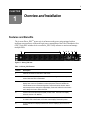
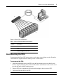
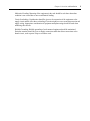
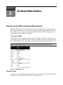
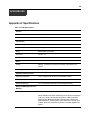
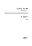
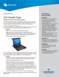
Direct_PDU
For Technical Support:
www.avocent.com/support
590-865-501A
Installer/User Guide
USA Notification
Warning: Changes or modifications to this unit not expressly approved by the party responsible for
compliance could void the user’s authority to operate the equipment.
Note: This equipment has been tested and found to comply with the limits for a Class A digital device,
pursuant to Part 15 of the FCC Rules. These limits are designed to provide reasonable protection
against harmful interference when the equipment is operated in a commercial environment. This equipment generates, uses and can radiate radio frequency energy and, if not installed and used in accordance with the instruction manual, may cause harmful interference to radio communications. Operation
of this equipment in a residential area is likely to cause harmful interference in which case the user will
be required to correct the interference at his own expense.
Canadian Notification
This digital apparatus does not exceed the Class A limits for radio noise emissions from digital apparatus set out in the Radio Interference Regulations of the Canadian Department of Communications.
Le présent appareil numérique n’émet pas de bruits radioélectriques dépassant les limites applicables
aux appareils numériques de la classe A prescrites dans le Règlement sur le brouillage radioélectrique
édicté par le Ministère des Communications du Canada.
Safety and EMC Approvals and Markings
RoHS C of C, UL, FCC, cUL, ICES-003, CE, C-Tick
Direct_PDU
Installer/User Guide
Avocent, the Avocent logo, Direct_PDU and the Power of Being There
are trademarks or registered trademarks of Avocent Corporation or its
affiliates in the U.S. and other countries. All other marks are the property
of their respective owners.
© 2008 Avocent Corporation. All rights reserved. 590-865-501A
Instructions
This symbol is intended to alert the user to the presence of important operating and maintenance (servicing)
instructions in the literature accompanying the appliance.
Dangerous Voltage
This symbol is intended to alert the user to the presence of uninsulated dangerous voltage within the product’s
enclosure that may be of sufficient magnitude to constitute a risk of electric shock to persons.
Power On
This symbol indicates the principal on/off switch is in the on position.
Power Off
This symbol indicates the principal on/off switch is in the off position.
Protective Grounding Terminal
This symbol indicates a terminal which must be connected to earth ground prior to making any other
connections to the equipment.
iii
T A B L E O F C ON T E N T S
Table of Contents
List of Figures .................................................................................................................. v
List of Tables .................................................................................................................. vii
Chapter 1: Overview and Installation ............................................................................. 1
Features and Benefits ........................................................................................................................ 1
Alarms and monitoring ............................................................................................................... 2
Sequential power application ..................................................................................................... 2
Getting Started ................................................................................................................................... 2
Rack Mounting the PDU.................................................................................................................... 3
Safety Precautions ............................................................................................................................. 4
Safety instructions....................................................................................................................... 4
Rack mount safety considerations .............................................................................................. 4
Chapter 2: On-Board Web Interface ............................................................................... 7
Overview of the PDU’s On-Board Web Interface ............................................................................. 7
Control screen ............................................................................................................................ 7
Network screen ........................................................................................................................... 8
ID screen..................................................................................................................................... 9
Email screen ............................................................................................................................... 9
Trap screen ............................................................................................................................... 10
Chapter 3: Direct_PDU Utility Software ....................................................................... 11
Overview of the PDU Utility Software ............................................................................................ 11
About The Direct_PDU Utility Software Interface Window ........................................................... 11
Using The Function Menu Bar ........................................................................................................ 13
Using the Device menu ............................................................................................................. 13
Using the Data Management menu .......................................................................................... 17
Using the System Management menu ....................................................................................... 17
Using PDU Information................................................................................................................... 22
Using the Group Information tab ............................................................................................. 22
Using the Device Information tab............................................................................................. 23
Using the Data Log tab ............................................................................................................ 26
Using the Events tab ................................................................................................................. 27
iv
Direct_PDU Installer/User Guide
Appendices..................................................................................................................... 29
Appendix A: Specifications .............................................................................................................. 29
Appendix B: Technical Support ....................................................................................................... 30
v
LIST OF FIGU RES
List of Figures
Figure 1.1: Direct_PDU Unit............................................................................................................ 1
Figure 1.2: Direct_PDU Configuration ............................................................................................ 3
Figure 2.1: OBWI Index Screen ........................................................................................................ 7
Figure 2.2: Control Screen ................................................................................................................ 8
Figure 2.3: Network Screen............................................................................................................... 9
Figure 2.4: ID Screen ........................................................................................................................ 9
Figure 2.5: Email Screen................................................................................................................. 10
Figure 2.6: Trap Screen................................................................................................................... 10
Figure 3.1: Direct_PDU Utility Software Login Screen ................................................................. 11
Figure 3.2: Direct_PDU Utility Software Interface Window.......................................................... 12
Figure 3.3: Add Device Screen........................................................................................................ 13
Figure 3.4: Device Edit Screen........................................................................................................ 14
Figure 3.5: Modify IP Screen .......................................................................................................... 14
Figure 3.6: Edit PDU Config. Screen.............................................................................................. 15
Figure 3.7: Add Group Screen ........................................................................................................ 16
Figure 3.8: Edit Group Name Screen .............................................................................................. 16
Figure 3.9: Scan Domain Screen..................................................................................................... 18
Figure 3.10: General Settings Screen.............................................................................................. 19
Figure 3.11: User List Screen.......................................................................................................... 20
Figure 3.12: Add User Screen ......................................................................................................... 20
Figure 3.13: Edit User Screen ......................................................................................................... 21
Figure 3.14: Database Setting Screen ............................................................................................. 21
Figure 3.15: Service Control Screen ............................................................................................... 22
Figure 3.16: Group Information Screen.......................................................................................... 23
Figure 3.17: Device Information Screen ......................................................................................... 24
Figure 3.18: PDU Information Screen ............................................................................................ 25
Figure 3.19: Data Log Screen ......................................................................................................... 26
Figure 3.20: Events Screen.............................................................................................................. 27
vi
Direct_PDU Installer/User Guide
vii
LIST OF TABLES
List of Tables
Table 1.1: Direct_PDU Features ...................................................................................................... 1
Table 1.2: Direct_PDU Configuration Descriptions ........................................................................ 3
Table 3.1: Direct_PDU Utility Software Interface Window Area Descriptions ............................. 12
Table 3.2: Device Summary Description ......................................................................................... 13
Table A.1: PDU Specifications ........................................................................................................ 29
viii
Direct_PDU Installer/User Guide
1
CHAPTER
Overview and Installation
1
Features and Benefits
The Avocent Direct_PDU™ power strip is an Internet-ready power strip equipped with an
intelligent current meter to indicate the total power consumption of the Power Distribution Unit
(PDU). Each PDU includes the Avocent Direct_PDU Utility software to monitor and manage
multiple PDUs.
8
7
6
5
4
Figure 1.1: Direct_PDU Unit
Table 1.1: Direct_PDU Features
Number
Description
1
Ethernet connection for the built-in web server.
2
An audible alarm that beeps once a second for a warning and three times per
second when the PDU is overloaded.
3
A function button that can be used to turn off the warning alarm, change the meter
display from current to IP address or reboot the power. Press and release the
function button to turn off the warning alarm. Press and hold the function button
until it beeps twice to change the meter display. Press and hold the function button
until it beeps six times to reboot the PDU.
4
A built-in true Root Meter Square (RMS) current meter. The meter can display
either the current or IP address.
5
Outlet LEDs labeled alphabetically to indicate the output power of the PDU. When
an outlet’s LED is illuminated, the current meter displays that outlet’s power.
6
An LED indicator that displays whether the meter is displaying the current or IP
address.
3
2 1
2
Direct_PDU Installer/User Guide
Table 1.1: Direct_PDU Features (Continued)
Number
Description
7
Depending on the model, the PDU has either 8 or 16 outlets.
8
A circuit breaker that provides protection during a power overload.
Alarms and monitoring
The PDU delivers accurate, real-time global current monitoring of all connected devices via the onboard web interface or through the Direct_PDU Utility software. Users have the ability to set a
current alarm threshold that, once exceeded, will cause the PDU to sound an alarm or send a
notification message, or both.
Sequential power application
The PDU incorporates a sequential power application feature that prevents all power outlet
receptacles from turning on at once, eliminating the potential of current surges that could render the
equipment inoperable. Together with the global current monitoring, the sequential power
application feature lets users safely install more equipment on existing power circuits without the
worry of current overloads.
Getting Started
Before installing your PDU, refer to the following list to ensure you have all items that shipped
with the PDU, as well as other items necessary for proper installation. The standard PDU package
includes the following:
• Power Distribution Unit
•
Rack mounting brackets
•
Four retaining screws for each rack mounting bracket
•
Quick Installation Guide to help mount and install a PDU
•
CD that contains this document, PDU Utility software and Management Information Base for
Network (directpdu.MIB)
Chapter 1: Overview and Installation
Ethernet
Connection
3
1
2
3
Figure 1.2: Direct_PDU Configuration
Table 1.2: Direct_PDU Configuration Descriptions
Number
Description
1
User station equipped with PDU Utility software
2
PDU
3
Devices plugged into the PDU
Rack Mounting the PDU
You may mount the Direct_PDU power strip in a rack or place it on a desktop or other flat surface.
Two brackets are supplied with four retaining screws for each bracket.
To rack mount the PDU:
1.
Attach the mounting brackets to the PDU using the four retaining screws provided for each
bracket. Align the mounting holes of the brackets with the notched holes on the vertical rail of
the rack and attach with the retaining screws.
2.
Plug the PDU into an appropriate wall outlet and then plug the devices into the PDU.
3.
Connect the Ethernet cable to the PDU.
NOTE: The default IP address of the PDU is 192.168.0.216 if the network does not have a DHCP server.
4
Direct_PDU Installer/User Guide
Safety Precautions
To avoid potential video and/or keyboard problems when using Avocent products:
•
If the building has 3-phase AC power, ensure that the server and monitor are on the same
phase. For best results, they should be on the same circuit.
To avoid potentially fatal shock hazard and possible damage to equipment, please observe the
following precautions:
•
Do not use a 2-wire extension cord in any Avocent product configuration.
•
Test AC outlets at the server and monitor for proper polarity and grounding.
Safety instructions
Read all the following safety guidelines to protect yourself and your PDU.
WARNING: All outlets of the PDU output high voltage. Necessary precautions should be taken.
WARNING: Do not push any objects through the openings of the PDU. Doing so may cause fire or electric shock
by shorting out interior components.
WARNING: There is a possibility of severe electrical shock from either the live or neutral side of any of the power
outlets or their wiring, even if one of the circuit breakers is disabled.
WARNING: The PDU is intended for indoor use only.
WARNING: To help protect the PDU from electrical power fluctuations, use a surge suppressor, line conditioner
or uninterruptible power supply.
WARNING: Be sure that nothing rests on the cables of the PDU and that it is not located where it may be
stepped on or tripped over.
WARNING: Do not spill food or liquids on the PDU. If it gets wet, disconnect the power immediately and contact
Avocent.
WARNING: Keep the PDU away from heat sources.
Rack mount safety considerations
When installing the PDU, make sure the following environmental specifications are met:
Elevated Operating Ambient Temperature: If the PDU is installed in a closed or multi-unit rack
assembly, the operating ambient temperature of the rack environment may be greater than room
ambient temperature. Therefore, consideration should be given to installing the equipment in an
environment compatible with the manufacturer’s maximum rated ambient temperature. See above.
Reduced Air Flow: Installation of the equipment in a rack should be such that the amount of air
flow required for safe operation of the equipment is not compromised.
Chapter 1: Overview and Installation
Mechanical Loading: Mounting of the equipment in the rack should be such that a hazardous
condition is not created due to uneven mechanical loading.
Circuit Overloading: Consideration should be given to the connection of the equipment to the
supply circuit and the effect that overloading of circuits might have on overcurrent protection and
supply wiring. Appropriate consideration of equipment nameplate ratings should be used when
addressing this concern.
Reliable Grounding: Reliable grounding of rack-mounted equipment should be maintained.
Particular attention should be given to supply connections other than direct connections to the
branch circuit, such as power strips or extension cords.
5
6
Direct_PDU Installer/User Guide
7
CHAPTER
2
On-Board Web Interface
Overview of the PDU’s On-Board Web Interface
The Direct_PDU power strip has an on-board web interface (OBWI) to monitor and manage the
PDU. Using the OBWI, you can view the PDU’s system information, threshold and status. You can
also monitor power consumption and control individual outlets on the PDU, configure network
settings and set up email and trap notifications.
To access the OBWI:
In the address field of the Windows® browser, type the IP address of the PDU. The Index screen
opens, displaying information about the PDU. Links are available at the bottom of the Index screen
to access other OBWI screens. These links are also available at the bottom of each OBWI screen.
NOTE: The PDU’s default IP address is 192.168.0.216 if the network does not have a DHCP server.
Figure 2.1: OBWI Index Screen
Control screen
The Control screen of the OBWI displays the PDU’s power consumption and status. It also displays
and allows you to control the status of the PDU’s individual outlets.
8
Direct_PDU Installer/User Guide
To turn outlets on or off from the Control screen:
1.
Click on the Control link at the bottom of the screen. The Control screen opens.
2.
Check the box next to the outlet you want to turn on or off.
3.
Enter the user ID and password in the appropriate fields.
NOTE: The default ID is snmp and the default password is 1234 for all screens.
4.
Select either the On or Off button at the bottom of the screen. The status of the outlets you
selected will change.
Figure 2.2: Control Screen
Network screen
Using the Network screen of the OBWI, you can view and configure network information for the
PDU.
To change network information for the PDU:
1.
Click on the Network link at the bottom of the screen. The Network screen opens.
2.
Make changes in the appropriate fields.
3.
Click the Update button.
Chapter 2: On-Board Web Interface
9
Figure 2.3: Network Screen
ID screen
Using the ID screen of the OBWI, you can change the user ID and password for the PDU.
To change the user ID and password:
1.
Click on the ID link at the bottom of the screen. The ID screen opens.
2.
Enter the original ID and password and new ID and password in the appropriate fields.
3.
Click the Update button.
Figure 2.4: ID Screen
Email screen
When a user-defined event occurs, the PDU Utility software can send an email notification. You
can configure where to send the email notification in the OBWI. You can configure the event using
the PDU Utility software. For more information on configuring the event, see To edit PDU
configuration: on page 15.
To configure an email notification:
1.
Click on the Email link at the bottom of the screen. The Email screen opens.
2.
Enter the email information in the appropriate fields.
10
Direct_PDU Installer/User Guide
3.
Click the Apply button.
Figure 2.5: Email Screen
Trap screen
When a user-defined event occurs, the PDU Utility software can send a trap notification. You can
configure where to send the trap notification in the OBWI. You can configure the event using the
PDU Utility software. For more information on configuring the event, see To edit PDU
configuration: on page 15.
To configure a trap notification:
1.
Click on the Trap link at the bottom of the screen. The Trap Screen opens.
2.
Enter your ID, password and receiver IP in the appropriate fields.
3.
Click the Update button.
Figure 2.6: Trap Screen
11
CHAPTER
3
Direct_PDU Utility Software
Overview of the PDU Utility Software
The Direct_PDU Utility is advanced PDU monitoring and management software. With the
Direct_PDU Utility software you can monitor groups of PDUs simultaneously, provide a power
consumption chart for daily, monthly or a user-defined period, send email and trap information to a
specific account and log and export events to a Syslog server.
To access the PDU Utility software:
1.
From the Windows Start menu, select Programs and then the Direct_PDU Utility software.
The login screen opens for the Direct_PDU Utility software.
2.
Enter your username and password.
NOTE: The default username is admin and the default password is 1234.
3.
Click OK. The PDU Utility software interface window opens.
Figure 3.1: Direct_PDU Utility Software Login Screen
About The Direct_PDU Utility Software Interface Window
When a user logs in and has been authenticated, the Direct_PDU Utility software interface window
appears. From this window, a user can monitor and manage multiple PDUs.
Figure 3.2 shows the areas of the Direct_PDU Utility interface window.
12
Direct_PDU Installer/User Guide
A
C
B
D
Figure 3.2: Direct_PDU Utility Software Interface Window
Table 3.1: Direct_PDU Utility Software Interface Window Area Descriptions
Letter
Description
A
Function Menu Bar - Use the Function Menu Bar to access the Device,
Data Management, System Management or Help menus.
B
PDU List - Lists all of the PDUs and associated outlets connected to the
network. Users can define a group to manage the PDUs.
C
PDU Information - This area provides detailed information about each PDU
connected to the network.
D
Device Summary - Shows the status of the PDUs and associated outlets
connected to the network.
Table 3.2 shows the meaning of the icons in the Device Summary field:
Chapter 3: Direct_PDU Utility Software
13
Table 3.2: Device Summary Description
Icon
Status
Critical
Output power of the PDU exceeds the overload setting.
Warning
Output power of the PDU exceeds the warning setting.
Unreachable
The PDU Utility can not communicate with the PDU.
Normal
The PDU is working normally.
Using The Function Menu Bar
Using the Device menu
Using the Device menu you can add, edit and remove both individual devices or groups of devices
connected to the PDU.
To add a device:
1.
From the Function Menu Bar, click Device-Add Device. The Add Device screen opens.
2.
Specify the settings for the device to be added in the appropriate fields.
3.
Click OK.
NOTE: The Community field must be the same - private or public - as the PDU in order for the PDU Utility
software to communicate with the PDU. The default setting is private.
Figure 3.3: Add Device Screen
14
Direct_PDU Installer/User Guide
To edit a device:
1.
Highlight the device to edit in the PDU List from the Direct_PDU Utility software interface
window.
2.
From the Function Menu Bar, click Device-Edit Device. The Device Edit screen opens.
3.
Specify the changes for the device in the appropriate fields.
4.
To change the method the Direct_PDU Utility software uses to obtain the IP address, click in
the IP Address field then click Modify in the Network Settings field.
5.
The Modify IP screen opens. Specify the changes in the appropriate fields and click OK.
Figure 3.4: Device Edit Screen
Figure 3.5: Modify IP Screen
To remove a device:
1.
Highlight the device to be removed in the PDU List from the Direct_PDU Utility software
interface window.
2.
From the Function Menu Bar, click Device-Remove Selected Device. The Device Delete
Confirmation screen opens.
Chapter 3: Direct_PDU Utility Software
3.
Click Yes to remove the device. A Record Delete Confirmation screen opens.
4.
Click Yes to delete the record.
15
-orClick No to keep the record.
To edit PDU configuration:
1.
Highlight the PDU to be edited in the PDU List from the Direct_PDU Utility software
interface window.
2.
From the Function Menu Bar, click Device-Edit PDU Config. The Edit PDU Config. screen
opens.
3.
A user can configure the PDU’s voltage settings, threshold settings and outlet name settings
from this screen. Set the values in the appropriate fields and click OK.
NOTE: The minimum warning current value is .6 amp.
Figure 3.6: Edit PDU Config. Screen
To update device information:
1.
Highlight the device in the PDU List from the Direct_PDU Utility software interface window.
2.
From the Function Menu Bar, click Device-Update Device Information. A screen opens
notifying you device information will be updated shortly.
To remove a PDU:
1.
Highlight the PDU to be removed in the PDU List from the Direct_PDU Utility software
interface window.
16
Direct_PDU Installer/User Guide
2.
From the Function Menu Bar, click Device-Remove Selected PDU. A screen opens to confirm
the deletion. Click Yes.
To add a device group:
1.
From the Function Menu Bar, click Device-Add Device Group. The Add Group screen opens.
2.
Enter the group name and click OK.
Figure 3.7: Add Group Screen
To edit a group:
1.
Highlight the group in the PDU List from the Direct_PDU Utility software interface window.
2.
From the Function Menu Bar, click Device-Edit Group. The Edit Group screen opens
displaying the original group name with a field for the new group name.
3.
Enter the new group name. Click OK.
Figure 3.8: Edit Group Name Screen
To remove a group:
1.
Highlight the group to be removed in the PDU List from the Direct_PDU Utility software
interface window.
2.
From the Function Menu Bar, click Device-Remove Device Group. The Group Delete
Confirmation screen opens.
3.
Click Yes to remove the group. A Group Delete Confirmation screen opens.
4.
Click Yes to delete the group.
-orClick No to keep the group.
NOTE: All devices must be removed individually from the group before the entire group can be removed.
Chapter 3: Direct_PDU Utility Software
17
Using the Data Management menu
Users can export and remove current accounting data, event logs and power consumption data from
the Function Menu Bar by clicking Data Management and then making the appropriate selection.
Current accounting data and event logs are exported in CSV format.
To export current data:
1.
Highlight the device with the accounting or events to export in the PDU List from the
Direct_PDU Utility software interface window.
2.
From the Function Menu Bar, click Data Management-Export kW*hr Account to CSV to
export current accounting. A save-as screen opens.
-orFrom the Function Menu Bar, click Data Management-Export Data Log to CSV to export
current data. A save-as screen opens.
-orFrom the Function Menu Bar, click Data Management-Export Events to CSV to export events.
A save-as screen opens.
3.
Select where you want to save the file, type a filename in the filename field and select Save.
To remove current data:
1.
Highlight the device with the accounting or events to be removed in the PDU List from the
Direct_PDU Utility software interface window.
2.
From the Function Menu Bar, click Data Management-Remove kW*hr Account Records to
remove current accounting records.
-orFrom the Function Menu Bar, click Data Management-Remove Data Log Records to remove
current data.
-orFrom the Function Menu Bar, click Data Management-Remove Event Records to remove
power consumption records.
3.
A confirmation screen opens. Select OK.
Using the System Management menu
Use the System Management menu to scan for devices, set general settings, manage users, set
database settings and control services.
18
Direct_PDU Installer/User Guide
To scan a subnet:
1.
From the Function Menu Bar, click System Management-Scan Subnet. The Scan Domain
screen opens. You can:
a.
Check Scan network interface subnet by making the appropriate selection.
-orb.
2.
Check Scan the specified subnet and type in the IP address obtained from the PDU.
Click Scan.
NOTE: The PDU will show the assigned IP address by pressing the Function button until the PDU beeps twice.
3.
Check the Add field next to the device to be added.
4.
In the Device Groups field, select a group for the device.
5.
Click OK.
NOTE: It may be necessary to scan more than once to get all of the IP addresses in the network.
Figure 3.9: Scan Domain Screen
Using the General Settings option
When a threshold has been exceeded, the PDU Utility software can send an email to as many as
three user-defined accounts. The PDU Utility software can send an event email for any of the PDUs
connected to the network.
Chapter 3: Direct_PDU Utility Software
19
To configure email settings:
1.
From the Function Menu Bar, click System Management-General Settings. The General
Settings screen opens.
2.
Check the box next to Enable to enable an email alert. Enter the appropriate information in the
fields. You can send email alerts to as many as three email addresses.
3.
Click OK.
Figure 3.10: General Settings Screen
Using the Users Lists option
To add a user:
1.
From the Function Menu Bar, click System Management-User List. The User List screen will
open.
2.
Click Add User. The Add User screen opens.
3.
Enter the username and password for the new user.
4.
Assign Read Only or Read/Write authority.
5.
Click OK.
20
Direct_PDU Installer/User Guide
Figure 3.11: User List Screen
Figure 3.12: Add User Screen
To edit a user:
1.
From the Function Menu Bar, click System Management-User List. The User List screen will
open.
2.
Click the Edit button next to the name of the user to edit. The Edit User screen opens.
3.
Make changes and click OK.
NOTE: A user can only change the password for the Admin account.
Chapter 3: Direct_PDU Utility Software
21
Figure 3.13: Edit User Screen
To use the database setting option:
1.
From the Function Menu Bar, click System Management-Database Setting. The Database
Setting screen will open.
2.
Select either Microsoft Access or MySQL and make changes in the appropriate fields.
3.
Click OK.
Figure 3.14: Database Setting Screen
To use the service control option:
1.
From the Function Menu Bar, click System Management-Service Control. The Service Control
screen will open.
2.
Control the service status by selecting either Start, Stop or Restart.
3.
Click OK.
22
Direct_PDU Installer/User Guide
Figure 3.15: Service Control Screen
Using PDU Information
Using the Group Information tab
From the Group Information tab, a user can monitor all the Direct_PDU power strips in the
network. Each PDU is listed under the Group Information tab along with its status. Each PDU’s
status is one of the following:
•
Normal - The PDU Utility software is communicating normally with the PDU.
•
Querying - The PDU Utility software is requesting data from the PDU.
•
Communication Lost - The PDU Utility software can not receive data from the PDU.
•
Warning - The power consumption of the PDU exceeds the warning threshold.
•
Overload - The power consumption of the PDU exceeds the overload threshold.
Chapter 3: Direct_PDU Utility Software
23
Figure 3.16: Group Information Screen
Using the Device Information tab
By clicking on a device in the PDU List from the Direct_PDU Utility software interface window
then clicking the Device Information tab, a user can see information on an individual device.
To update device information:
1.
Click on IP Address under Network Information.
2.
Click Update to get an update on device information.
24
Direct_PDU Installer/User Guide
Figure 3.17: Device Information Screen
Using the PDU Information tab
To monitor power consumption:
1.
From the PDU List, highlight the PDU to monitor.
2.
Click on the PDU Info tab.
3.
Check Daily, Monthly or Custom, then select the date, month or custom time frame in the
appropriate field.
4.
Click Update.
Chapter 3: Direct_PDU Utility Software
Figure 3.18: PDU Information Screen
25
26
Direct_PDU Installer/User Guide
Using the Data Log tab
Click on the Data Log tab to see details of the PDU’s power consumption. You can select options
to see power consumption by month or by a custom range.
To see details of the PDU’s power consumption:
1.
From the PDU List, highlight the PDU to monitor.
2.
Click on the Data Log tab.
3.
Select either Current or Power under Log Type.
4.
Choose to see power consumption by month or a custom range.
5.
Click Update.
Figure 3.19: Data Log Screen
Chapter 3: Direct_PDU Utility Software
Using the Events tab
The Events tab shows a list of PDU events.
To see a list of all PDU events:
1.
Click on the Events tab.
2.
Choose to see events by month or a custom range.
3.
Click Update.
Figure 3.20: Events Screen
27
28
Direct_PDU Installer/User Guide
29
APP ENDICE S
Appendices
Appendix A: Specifications
Table A.1: PDU Specifications
Interface
RJ-45
Ethernet
Nominal Input Frequency
47-63 Hz Full Range
LED Indicator
Indicator
one yellow LED, one red LED
Current Meter
three digits
Range
0AMP-20AMP (True RMS)
Resolution
0A-20A: .1A
Precision
0A-20A: +/-2%+/-0.1AMP
Alarm
Audible
Warning - one beep in one second; Overload - three beeps in one
second
Seven Segment
Warning and Overload - Meter will flash once in one second
Operation and Environment
Operating Temperature
23 to 113 degrees Fahrenheit (-5 to 45 degrees Celsius)
Relative Humidity
0 to 95 percent
Storage Temperature
-13 to 149 degrees Fahrenheit (-25 to 65 degrees Celsius)
Safety and EMC Approvals and
Markings
RoHS C of C, UL, FCC, cUL, ICES-003, CE, C-Tick
Safety certifications and EMC certifications for this product are obtained
under one or more of the following designations: CMN (Certification
Model Number), MPN (Manufacturer’s Part Number) or Sales Level
Model designation. The designation that is referenced in the EMC and/
or safety reports and certificates are printed on the label applied to this
product.
30
Direct_PDU Installer/User Guide
Appendix B: Technical Support
Our Technical Support staff is ready to assist you with any installation or operating issues you
encounter with your Avocent product. If an issue should develop, follow the steps below for the
fastest possible service.
To resolve an issue:
1.
2.
Check the pertinent section of this manual to see if the issue can be resolved by following the
procedures outlined.
Visit www.avocent.com/support and use one of the following resources:
Search the knowledge base or use the online service request.
-orSelect Technical Support Contacts to find the Avocent Technical Support location nearest you.
USA Notification
Warning: Changes or modifications to this unit not expressly approved by the party responsible for
compliance could void the user’s authority to operate the equipment.
Note: This equipment has been tested and found to comply with the limits for a Class A digital device,
pursuant to Part 15 of the FCC Rules. These limits are designed to provide reasonable protection
against harmful interference when the equipment is operated in a commercial environment. This equipment generates, uses and can radiate radio frequency energy and, if not installed and used in accordance with the instruction manual, may cause harmful interference to radio communications. Operation
of this equipment in a residential area is likely to cause harmful interference in which case the user will
be required to correct the interference at his own expense.
Canadian Notification
This digital apparatus does not exceed the Class A limits for radio noise emissions from digital apparatus set out in the Radio Interference Regulations of the Canadian Department of Communications.
Le présent appareil numérique n’émet pas de bruits radioélectriques dépassant les limites applicables
aux appareils numériques de la classe A prescrites dans le Règlement sur le brouillage radioélectrique
édicté par le Ministère des Communications du Canada.
Safety and EMC Approvals and Markings
RoHS C of C, UL, FCC, cUL, ICES-003, CE, C-Tick
Direct_PDU
For Technical Support:
www.avocent.com/support
590-865-501A
Installer/User Guide