1
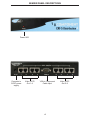
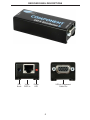
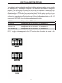
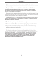
1x8 Component
CAT-5 DA
USER
MANUAL
www.gefen.com
ASKING FOR ASSISTANCE
Technical Support:
Telephone
(818) 772-9100
(800) 545-6900
Fax
(818) 772-9120
Technical Support Hours:
8:00 AM to 5:00 PM Monday through Friday PST
Write To:
Gefen Inc.
C/O Customer Service
20600 Nordhoff St.
Chatsworth, CA 91311
www.gefen.com
[email protected]
Notice
Gefen Inc. reserves the right to make changes in the hardware, packaging and any
accompanying documentation without prior written notice.
1x8 Component CAT5 DA is a trademark of Gefen Inc.
© 2007 Gefen Inc., All Rights Reserved
TABLE OF CONTENTS
1
Operation Notes
2
Introduction
3
Features
4
Sender Panel Descriptions
5
Receiver Panel Descriptions
6
Connecting and Operating the 1x8 Component CAT5 DA
7
How to Adjust the Picture
8
CAT5 Wiring Diagram
9
Specifications
10
Warranty
OPERATION NOTES
READ THESE NOTES BEFORE INSTALLING
OR OPERATING THE 1X8 COMPONENT CAT5 DA SYSTEM
• Use industry standard Category-5 (CAT-5) cable to operate the 1x8 Component CAT5
DA system. CAT-5e cable is preferred.
• Please connect all the cables between the computer and the 1x8 Component CAT5 DA
system before powering up the 1x8 Component CAT5 DA Sender unit.
• The 1x8 Component CAT5 DA units are housed in a metal box for better RF shielding.
1
INTRODUCTION
Congratulations on your purchase of the ex•tend•it 1x8 Component CAT5 Distribution
Amplifier. Your complete satisfaction is very important to us.
Gefen’s line of Home Theater switchers, extenders, and Distribution Amplifiers are designed to make your A/V setup more comfortable, more productive and more affordable.
The 1x8 Component CAT5 DA allows one Component source to be distributed on up
to eight displays. The 1x8 Component CAT5 DA also extends Component signals over
330 feet using industry standard Category 5 (CAT-5) Cable. All output displays will have
mirrored images.
The ex•tend•it line offers solutions for home theater, A/V installation, data center, information distribution, conference room presentation, school and corporate training environments.
Our Commitment
Gefen will always offer the finest quality product at the best possible price. Included in
that price is a lifetime support from a team of outstanding engineers.
How it Works
Simply connect your Component video source to the 1x8 Component CAT5 Distribution Amplifier’s input using the supplied VGA to Component cable. Then connect up to
eight Component displays to the Component CAT5 receivers over 330 feet using CAT-5
Cable. Then power the 1x8 Component CAT5 Distribution Amplifier and the receivers
will get power from the CAT5. Note: Component output 1 is the primary connection and
is used for the main display. Component output 2 through 8 follow the main display. The
Component displays attached to the 1x8 Component CAT5 Distribution Amplifier MUST
have the same native resolution in order to get a picture.
2
FEATURES
Features
• Distributes easily up to eight Component displays
• Extends each display up to 330 feet
• Maintains 480i, 480p, 720p, 720i, and 1080i, 1080p resolutions
• Distributes and extends Component or VGA video signals
• Installs in seconds
Includes:
(1) 1x8 Component CAT5 DA
(1) 6’ VGA to Component cable
(1) 5V6A DC Power Supply
(1) Users Manual
3
SENDER PANEL DESCRIPTIONS
Power LED
Connects to
5VDC power
supply
Video CAT5
Out 1-4
VGA to Component
Cable Input
4
Video CAT5
Out 5-8
RECEIVER PANEL DESCRIPTIONS
EQ
Knob
Video
CAT5 In
Power
LED
VGA to Component
Cable Out
5
CONNECTING AND OPERATING THE 1X8 COMPONENT CAT5 DA
How to Connect the 1x8 Component CAT5 DA to your devices
1 Connect the supplied VGA to Component cable from the Component video source into
the 1x8 Component CAT5 DA Sender "Comp In" port.
2 Connect a CAT-5e* cable from the "CAT5 Video Outs" on the 1x8 Component CAT5
DA Sender to the "CAT5 Inputs" on the Component CAT5 Distribution Receiver. (Repeat
for each Receiver unit)
3 Connect the VGA to Component cable from the display to the "Comp Out" on the
Component CAT5 Distribution Receiver. (Repeat for each Receiver unit)
4 Plug the 5VDC power supply into the 1x8 Component CAT5 DA Sender.
6
HOW TO ADJUST THE PICTURE
The first step in adjusting the video quality is to display text and a graphic on your monitor
(i.e. desktop icons). Then set your computer to the resolution that you will be using most
frequently. The dip switches are used to set the focus and sharpness of the picture to the
best possible setting. Set the dip switches to the settings that are recommended for the
different lengths of CAT5 cable (see chart below). Verify that the picture quality is to your
satisfaction. If the recommended setting does not produce a great quality picture, try using
a different dip switch setting. The trim pod next to the Component connector on the 1x8
Component CAT5 DA R allows brightness adjustments for video.
0-25 Feet
26-100 Feet
101-200 Feet
201-300 Feet
301 Feet and Up
All dip switches OFF for all colors.
Set dip switch #1 ON all colors. 2,3,4 remain OFF.
Set dip switch #2 ON all colors. 1,3,4 remain OFF.
Set dip switch #3 ON all colors. 1,2,4 remain OFF.
Set dip switch #4 ON all colors. 1,2,3 remain OFF.
NOTE: The dip switches are set to the OFF position when the switch is closest to the
number or in the down position.
7
8
1
8
8
7
6
5
4
3
2
1
RJ-45 Jack
Brown
White/Brown
Green
White/Blue
Blue
White/Green
Orange
White/Orange
8
7
6
5
4
3
2
1
1
8
RJ-45 Jack
CAT5 WIRING DIAGRAM
SPECIFICATIONS
Video Amplifier Bandwidth .................................................................................. 350 MHz
Input Video Signal ......................................................................................... 1.2 volts p-p
Input DDC Signal .................................................................................... 5 volts p-p (TTL)
Horizontal Frequency Range ......................................................................... 15 - 70 KHz
Vertical Frequency Range ........................................................................... 30 - 170 KHz
Single Link Range .............................................................................1080p / 1920 x 1200
Input Connector Type ............................................................................................. HD-15
Output Connector Type .......................................................................................... HD-15
Link Connector Type ............................................................................................... RJ-45
Power Consumption ................................................................................ 30 Watts (max.)
Power Supply .......................................................................................................... 5VDC
Dimensions .................................................................................. 8.5”W x 1.75”H x 4.5”D
Shipping Weight ....................................................................................................... 3 Lbs
9
WARRANTY
Gefen Inc. warrants the equipment it manufactures to be free from defects in material
and workmanship.
If equipment fails because of such defects and Gefen Inc. is notified within two
(2) year from the date of shipment, Gefen Inc. will, at its option, repair or replace
the equipment, provided that the equipment has not been subjected to mechanical,
electrical, or other abuse or modifications.
Equipment that fails under conditions other than those covered will be repaired at the
current price of parts and labor in effect at the time of repair. Such repairs are warranted
for ninety (90) days from the day of reshipment to the Buyer.
This warranty is in lieu of all other warranties expressed or implied, including without
limitation, any implied warranty or merchantability or fitness for any particular purpose,
all of which are expressly disclaimed.
1. Proof of sale may be required in order to claim warranty.
2. Customers outside the US are responsible for shipping charges to and from Gefen.
3. Copper cables are limited to a 30 day warranty and cable must be free from any
scratches, markings, and neatly coiled.
The information in this manual has been carefully checked and is believed to be
accurate. However, Gefen Inc. assumes no responsibility for any inaccuracies that may
be contained in this manual. In no event will Gefen Inc., be liable for direct, indirect,
special, incidental, or consequential damages resulting from any defect or omission
in this manual, even if advised of the possibility of such damages. The technical
information contained herein regarding 1x8 Component CAT5 DA features and
specifications is subject to change without notice.
10