1
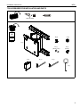
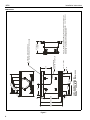
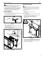
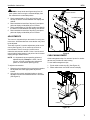
INSTALLATION INSTRUCTIONS
Instrucciones de instalación
Installationsanleitung
Instruções de Instalação
Istruzioni di installazione
Installatie-instructies
Instructions d´installation
Medium Flat Panel Wall Mount
Spanish Product Description
German Product Description
Portuguese Product Description
Italian Product Description
Dutch Product Description
French Product Description
MPW
MPW
Installation Instructions
DISCLAIMER
Milestone AV Technologies, and its affiliated corporations and
subsidiaries (collectively, "Milestone"), intend to make this
manual accurate and complete. However, Milestone makes no
claim that the information contained herein covers all details,
conditions or variations, nor does it provide for every possible
contingency in connection with the installation or use of this
product. The information contained in this document is subject
to change without notice or obligation of any kind. Milestone
makes no representation of warranty, expressed or implied,
regarding the information contained herein. Milestone assumes
no responsibility for accuracy, completeness or sufficiency of
the information contained in this document.
CAUTION: A CAUTION alerts you to the possibility of
Chief® is a trademark of Milestone AV Technologies. All rights
reserved.
WARNING: Failure to provide adequate structural strength
IMPORTANT WARNINGS AND
CAUTIONS!
damage or destruction of equipment if you do not follow the
corresponding instructions.
WARNING: Failure to read, thoroughly understand, and
follow all instructions can result in serious personal injury,
damage to equipment, or voiding of factory warranty! It is the
installer’s responsibility to make sure all components are
properly assembled and installed using the instructions
provided.
for the installation of this kit can result in serious personal
injury or damage to equipment! It is the installer’s
responsibility to make sure the structure to which this mount
is attached can support five times the combined weight of all
equipment.
WARNING: Exceeding the weight capacity can result in
WARNING: A WARNING alerts you to the possibility of
serious injury or death if you do not follow the instructions.
serious personal injury or damage to equipment! It is the
installer’s responsibility to make sure the combined weight of
all components attached to this mount does not exceed
125 lbs (56.7 kg).
LEGEND
2
Tighten Fastener
Adjust
Apretar elemento de fijación
Ajustar
Befestigungsteil festziehen
Einstellen
Apertar fixador
Ajustar
Serrare il fissaggio
Regolare
Bevestiging vastdraaien
Afstellen
Serrez les fixations
Ajuster
Loosen Fastener
Hex-Head Wrench
Aflojar elemento de fijación
Llave de cabeza hexagonal
Befestigungsteil lösen
Sechskantschlüssel
Desapertar fixador
Chave de cabeça sextavada
Allentare il fissaggio
Chiave esagonale
Bevestiging losdraaien
Zeskantsleutel
Desserrez les fixations
Clé à tête hexagonale
Installation Instructions
MPW
TOOLS REQUIRED FOR INSTALLATION AND PARTS
5/32" (Ø 4mm)
I/M
B (2)
x1
C (2)
A (1)
D (1)
(10-24 x 1/2")
F (4)
G (1)
E (1)
(10-24)
H (1)
J (1)
3
4
Figure 1
1.00
2.25
8.00
8.00
13.50
16.00
13.50
18.00
CHIEF MANUFACTURING INC.
MOUNT ORDER NUMBER IS MPW-XXXX
PHONE: 1-800-582-6480
2.50
16.27 15.52 10.27
2.63
.38
2.25
13.50
11.25
9.00
6.75
4.50
.28
1/4" X 1" SLOT
APPROXIMATE
CENTER OF DISPLAY
7.78
NOTE: INTERFAC E BRAC KET ATTACH ED TO BACK OF DISPLAY
ADDS D EPTH TO IN STALLATION (.5" AVERAGE). SEE TEC HNICAL
DRAWI NG OF MSB-XXXX FOR D IMENSION.
8.75 MAX
1.5 MIN
MOUNTING BUTTON ON BACK
OF D ISPLAY OR BRACKET GOES HERE
MPW
Installation Instructions
DIMENSIONS
Installation Instructions
MPW
MOUNT INSTALLATION
WARNING: IMPROPER INSTALLATION CAN LEAD TO
MOUNT FALLING CAUSING SERIOUS PERSONAL
INJURY OR DAMAGE TO EQUIPMENT! It is the installer’s
responsibility to make sure the structure to which the mount
is being installed is capable of supporting five times the
combined weight of the mount and all attachments.
WARNING: The installer is responsible for verifying that
the structure to which the mount is anchored will safely
support five times the combined load of the mount and all
attached components.
MOUNT ASSEMBLY
To install mount:
To attach the wall plate end caps:
1.
2.
1.
Slide one end cap (F) into each end of upper and lower wall
plates ON MOUNT (A). (See Figure 2)
(F) x 4
Identify appropriate mounting location.
Locate studs.
NOTE: The MPW is designed to be mounted on 16" on center
wood studs.
3. Place mount assembly (A) against wall, level mount, and
mark four pilot hole locations (See Figure 4).
4. Drill four 5/32" pilot holes at marked locations.
(See Figure 4).
(A) x 1
3
Figure 2
4
Wall Studs
5/32" Pilot Hole
To attach the cable management clips:
1.
2.
Pull mount face plate outward until access to rear of face
plate can be achieved.
Install two cable management clips (B) into each side of
mount faceplate. (See Figure 3)
Face Plate
(B) x 2
(A) x 1
Figure 4
5.
6.
Place mount assembly (A) against wall and align mounting
holes in mount assembly with pilot holes (See Figure 5).
Secure mount (A) to wall studs using four 1/4" x 2" lag
screws, and four flat washers.
Face Plate
Figure 3
5
MPW
Installation Instructions
mount assembly.
NOTE: If desired, install optional security screw and locknut
provided. The display can also be locked in the
retracted position by installing the optional locking pin
provided. (See Figure 8)
Teardrop
Mounting Hole
(4 places)
Latching Flag
(A) x 1
Figure 5
INSTALL DISPLAY
1.
Install interface bracket following the installation
instructions included with the bracket.
WARNING: IMPROPER INSTALLATION CAN LEAD TO
MOUNT FALLING CAUSING SEVERE PERSONAL INJURY
OR DAMAGE TO EQUIPMENT. Displays can weigh in
excess of 40 lbs (18.1kg). ALWAYS use two people and
proper lifting techniques when installing display.
2.
3.
Mounting Button
(On Display)
Lower latching flag. (See Figure 7)
Move mount faceplate to extended position by grasping
faceplate and pulling outward away from wall.
(See Figure 6)
Faceplate
CAUTION: Keep hands and fingers away from all pinch
Figure 7
points when moving the mount from retracted to extended
position.
Locking Pin
Faceplate
Faceplate
(A) x 1
Figure 6
4.
5.
6.
7.
6
Align mounting buttons on display with teardrop mounting
holes in mount faceplate (See Figure 7).
Move display forward until all four mounting buttons are
through teardrop mounting holes in faceplate, and recessed
area of mounting buttons is aligned with the lower area of
teardrop mounting holes in faceplate.
Lower display until the recessed area of all four mounting
buttons is seated in the lower area of teardrop mounting
holes in faceplate. (See Figure 7)
Move latching flag to the UP position to secure display to
Figure 8
FELT PAD INSTALLATION
Felt pads (C) are provided to protect the display from
contact with the mount.
To install protective felt pads:
1. Move display to fully extended position.
Installation Instructions
MPW
WARNING: Keep hands and fingers away from all
pinch points when moving the mounted display from
the retracted to the extended position.
2. Slowly rotate display to "fully right" position and
identify the area of contact between the display and
cabinet.
3. Remove adhesive back from felt pad (C) and place
pad onto display at identified point of contact.
4. Slowly rotate display to "fully left" position and identify
the area of contact between the display and cabinet.
5. Remove adhesive back from felt pad (C) and place
pad onto display at identified point of contact.
ADJUSTMENTS
Decrease Tension
Increase Tension
6
1
3
4
5
The mount is shipped with pre-set tension for swing arm
movement. After extended use mount tension may need
to be adjusted.
There are a total of 12 tension adjustment points on the
mount (See Figure 9). Six on mount top, and six on
mount bottom. Points 1 through 6 control mount
extension and retraction tension. Points 1 and 6 control
mount right left swing tension, and points 3 and 4 control
display left right rotation tension.
NOTE: It is important that corresponding points are
adjusted equally. Example: 1 and 6, 2 and 5,
3 and 4, and their corresponding adjustment
points on mount bottom (See Figure 9).
To adjust mount tension:
1. Determine which aspect of mount movement needs to
be adjusted and locate appropriate adjustment
screws.
2. Using the hex wrench provided, tighten or loosen
adjustment screws until desired tension is achieved
(See Figure 9).
2
Figure 9
CABLE MANAGEMENT
Cable management clips, for use with "zip-ties" or similar
devices, are provided for cable routing.
To use cable management clips:
1. Zip tie cable to cable clip (B). (See Figure 10)
2. Route cables down and under mount to display.
Zip Tie
(B) x 1
Cable
Figure 10
7
MPW
Installation Instructions
USA/International
Europe
Chief Manufacturing, a division of
Milestone AV Technologies
8832-000214 RevB
2008 Milestone AV Technologies
www.chiefmfg.com
10/08
Asia Pacific
A
P
F
A
P
F
A
8401 Eagle Creek Parkway, Savage, MN 55378
800.582.6480 / 952.894.6280
877.894.6918 / 952.894.6918
Fellenoord 130 5611 ZB EINDHOVEN, The Netherlands
+31 (0)40 2668620
+31 (0)40 2668615
Room 24F, Block D, Lily YinDu International Building
LuoGang, BuJi Town, Shenzhen, CHINA.
P +86-755-8996 9226
F +86-755-8996 9217