1
TM-H5000/H5000P
Operator’s Manual
Using this online operator’s guide
The words on the left side of this screen are bookmarks for all the
topics in this guide.
Use the scroll bar next to the bookmarks to find any topic you
want. Click a bookmark to instantly jump to its topic. (If you wish,
you can increase the size of the bookmark area by dragging the
dividing bar to the right.)
Use the scroll bar on the right side of this screen to move through
the text.
Use the zoom tools to magnify or reduce the page display.
Click the Find button if you want to search for a particular term.
(However, using the bookmarks is usually quicker.)
Complete online documentation for Acrobat Reader is located in the Help directory for Acrobat Reader.
Return to main menu
hybrid printer
TM-H5000/H5000P
Operator’s Manual
MICR Option Included
400613704
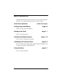
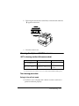
Printer Parts and Labels
Paper roll cover
Auto-cutter cover
Paper roll
control panel
POWER
ERROR
PAPER
OUT
Front cover
FEED
On/Off switch
Slip paper
control panel
FORWARD
REVERSE
POWER
ERROR
RELEASE
SLIP
RELEASE
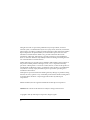
Labels
2
1
Ribbon installation
label inside
front cover
Label affixed on
the document table
Label inside
cutter section
Slide open this cutter cover
only when paper roll cover
cannot be opened.
Label inside paper
roll cover
Instruction label for when
cover won’t open
This label is packed with the printer
Affix the label at the side of the
printer
CAUTION:
Caution labels for drawer kick-out and display module
connectors.
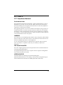
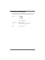
Quick Reference
This Quick Reference will direct you to key areas of this Operator’s
Manual. For a complete listing of topics, see the Contents.
Printer Parts and Labels
Ordering Paper and Ribbons
inside front cover
page viii
Where to order paper and ribbons.
Setting Up the Printer
page 1-1
How to set up the printer.
Installing and Replacing Paper
page 1-10
How to load or change the roll paper.
Validating and Verifying Checks
page 2-5
How to validate and verify checks using the optional Magnetic Ink
Character Recognition (MICR) Reader.
Solving Problems
page 3-1
How to correct problems.
i
All rights reserved. No part of this publication may be reproduced, stored in a
retrieval system, or transmitted in any form or by any means, electronic, mechanical,
photocopying, recording, or otherwise, without the prior written permission of Seiko
Epson Corporation. No patent liability is assumed with respect to the use of the
information contained herein. While every precaution has been taken in the
preparation of this book, Seiko Epson Corporation assumes no responsibility for
errors or omissions. Neither is any liability assumed for damages resulting from the
use of the information contained herein.
Neither Seiko Epson Corporation nor its affiliates shall be liable to the purchaser of
this product or third parties for damages, losses, costs, or expenses incurred by
purchaser or third parties as a result of: accident, misuse, or abuse of this product or
unauthorized modifications, repairs, or alterations to this product, or (excluding the
U.S.) failure to strictly comply with Seiko Epson Corporation’s operating and
maintenance instructions.
Seiko Epson Corporation shall not be liable against any damages or problems arising
from the use of any options or any consumable products other than those designated
as Original Epson Products or Epson Approved Products by Seiko Epson
Corporation.
EPSON and ESC/POS are registered trademarks of Seiko Epson Corporation.
NOTICE: The contents of this manual are subject to change without notice.
Copyright © 1996 by Seiko Epson Corporation, Nagano, Japan.
ii
FCC CLASS A
FCC Compliance Statement
For American Users
This equipment has been tested and found to comply with the limits for a Class A
digital device, pursuant to Part 15 of the FCC Rules. These limits are designed to
provide reasonable protection against harmful interference when the equipment is
operated in a commercial environment.
This equipment generates, uses, and can radiate radio frequency energy and, if not
installed and used in accordance with the instruction manual, may cause harmful
interference to radio communications. Operation of this equipment in a residential
area is likely to cause harmful interference, in which case the user will be required to
correct the interference at his own expense.
WARNING
The connection of a non-shielded printer interface cable to this printer will invalidate
the FCC Verification of this device and may cause interference levels which exceed
the limits established by the FCC for this equipment.
You are cautioned that changes or modifications not expressly approved by the
party responsible for compliance could void your authority to operate the
equipment.
FOR CANADIAN USERS
This Class A digital apparatus meets all requirements of the Canadian InterferenceCausing Equipment Regulations.
Cet appareil numérique de la classe A respecte toutes les exigenves du Règlement
sur le matériel brouileur du Canada.
GEREÄUSCHPEGEL
Gemäß der Dritten Verordnung zum Gerätesicherheitsgesetz
(Maschinenlärminformations- Verordnung-3. GSGV) ist der arbeitsplatzbezogene
Geräusch-Emissionswert kleiner als 70 dB(A) (basierend auf ISO 7779).
iii
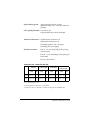
DECLARATION OF CONFORMITY
Product Name:
Printer
Type Name:
M128A
These printers conform to the following Directives and Norms
Directive 89/336/EEC
EN 55022 (1986 and 1994) Class B
EN 50082-1 (1992)
IEC 801-2 (1991)
IEC 801-3 (1984)
IEC 801-4 (1991)
Directive 90/384/EEC
EN45501: (1992)
iv
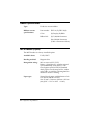
EMI and Safety Standards Applied
The following standards are applied only to the printers that are so
labeled. (EMC is tested using the EPSON PS-170 power supply)
Europe:
CE marking
EN55022
EN50082-1
EN45501
Safety Standard: TÜV
North America:
EMI: FCC Class A
Safety standards: UL 1950-2TH-D3
C-UL
Japan:
EMI: VCCI Class 1
v
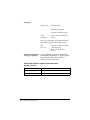
About This Manual
Setting Up and Using
❏
Chapter 1 contains information on unpacking the printer, setting it up, setting
the DIP switches, and adjusting the paper near end sensor.
❏
Chapter 2 contains information on using the printer.
❏
Chapter 3 contains troubleshooting information.
Reference
❏
Chapter 4 contains specifications
❏
Appendix A tells how to change the DIP switch and paper near end settings,
and Appendix B lists the EPSON Sales Subsidiaries and their addresses.
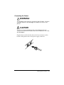
Warnings, Cautions, and Notes
WARNING:
Warnings must be followed carefully to avoid serious bodily
injury.
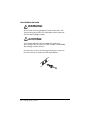
CAUTION:
Cautions must be observed to avoid minor injury to yourself or
damage to your equipment.
Note:
Notes have important information and useful tips on the operation of your
printer.
vi
Introduction
Features
The TM-H5000 and TM-H5000P are high-quality POS printers that can print on slip
and receipt paper (paper roll). The printers have the following features:
Slip Section
❏
Wide slip paper capability (maximum characters per line: 88 with 7 × 9 font).
❏
Copy printing is possible.
❏
High throughput using bidirectional, minimum distance printing.
❏
Optional Magnetic Ink Character Recognition (MICR) reader that enables the
printer to perform consecutive reading and processing of MICR characters and
printing endorsements.
Receipt Section
❏
High speed printing with collective printing.
❏
The standard auto-cutter provides easy user operation.
❏
Ladder bar code printing is possible by using a bar code command.
❏
New paper handling enables easy paper roll loading.
Both Receipt and Slip
❏
EPSON customer display series connection (DM-D102-012/DM-D203-012).
❏
Selectable receive buffer size (45 bytes or 4K bytes).
❏
Command protocol based on the ECS/POS® standard.
❏
Automatic Status Back (ASB) function that automatically transmits changes in
the printer status.
Introduction vii
Options and Accessories
❏
Magnetic Ink Character Recognition (MICR) reader (factory installed option)
❏
Direct connection display modules, DM-D102-012 and DM-D203-012
❏
EPSON power supply unit, PS-170
❏
EPSON ribbon cassette, ERC-31(P)
❏
Front extension table (WT-5000)
Ordering Paper and Supplies
Thermal paper can be ordered from the supplier in your area.
Specified Thermal Paper: NTP080-80
In Japan:
Nakagawa Seisakujo
2-5-21 Nishiki-Cho Warabi-Shi
Saitama-Ken 335 Japan
Tel: (048) 444-8211
Fax: (048) 443-6652
In U.S.A.:
Nakagawa Mfg (USA) Inc.
2305 Lincoln Avenue
Hayward, CA 94545 USA
Tel: (510) 782-0197
Fax: (510) 782-7124
In Europe:
Nakagawa Mfg (Europe) GmbH.
Krützpoort 16, 47804
Krefeld, Germany
Tel: 02151-711051
Fax: 02151-713293
viii Introduction
In Southeast Asia:
N.A.K. Mfg (Malaysia) SDN BHD
Lot 19-11, Bersatu Industrial Complexs,
Jalan Satu, Kaw Per. Cheras Jaya,.
Balakong Industrial Area, 43200 Cheras.
Selangor Darul Ehsan, Malaysia
Tel: 03-9047896, 9047900, 9047691
Fax: 03-9047889
Other Qualified Suppliers for Thermal Paper
The following suppliers sell thermal paper that may be used if
desired. Contact each company for information.
Original paper:
TF50KS-E
Nippon Paper Industry Co., Ltd.
1-12-1, Yuraku-Cho, Chiyoda-Ku
Tokyo 100 Japan
Tel: 03-3218-8000
Fax: 03-3216-1375
Original paper:
PD 160R
New Oji Paper Mfg. Co., Ltd.
7-5 Ginza 4-Chome Chuo-Ku
Tokyo 104 Japan
Tel: 03-3563-4800
Fax: 03-3563-1136
Original paper:
AF50KS-E
Jujo Thermal Oy (Finland)
P.O. Box 92 FIN27501 Kauttua Finland
Tel: 38-3932900
Fax: 38-3932419
Introduction ix
Original paper:
F380
Kanzaki Specialty Papers, Inc.
Cummings Street
Ware, MA 01082 U.S.A.
Tel: (413)967-6204
Fax: (413) 734-5101
Ordering Ribbon Cassettes
The TM-H5000/H5000P uses a long-lasting ribbon cassette in the
slip section. To order ribbon cassettes, contact your dealer or your
local affiliate. See Appendix B for a list of EPSON subsidiaries with
their addresses and telephone numbers.
x Introduction
Contents
Quick Reference . . . . . . . . . . . . . . . . . . . . . . . . . . . . . . . . . . . . . . . . . . . . . . . . . . . . . . . i
Introduction . . . . . . . . . . . . . . . . . . . . . . . . . . . . . . . . . . . . . . . . . . . . . . . . . . . . . . . . . . vii
Chapter 1 Setting Up the Printer
Unpacking . . . . . . . . . . . . . . . . . . . . . . . . . . . . . . . . . . . . . . . . . . . . . . . . . . . . . . . . . . . . 1-1
Removing the protective material . . . . . . . . . . . . . . . . . . . . . . . . . . . . . . . . . . . . 1-2
Connecting the Cables and Grounding the Printer . . . . . . . . . . . . . . . . . . . . . . . . . . 1-3
Connecting the Drawer . . . . . . . . . . . . . . . . . . . . . . . . . . . . . . . . . . . . . . . . . . . . . 1-5
Connecting the Display Module . . . . . . . . . . . . . . . . . . . . . . . . . . . . . . . . . . . . . 1-7
Grounding the Printer . . . . . . . . . . . . . . . . . . . . . . . . . . . . . . . . . . . . . . . . . . . . . . 1-7
Connecting the Power Supply . . . . . . . . . . . . . . . . . . . . . . . . . . . . . . . . . . . . . . . 1-8
Installing or Replacing the Paper Roll . . . . . . . . . . . . . . . . . . . . . . . . . . . . . . . . . . . . . 1-10
Installing the Ribbon Cassette . . . . . . . . . . . . . . . . . . . . . . . . . . . . . . . . . . . . . . . . . . . 1-13
Using the Power Switch Cover . . . . . . . . . . . . . . . . . . . . . . . . . . . . . . . . . . . . . . . . . . . 1-15
Self Test . . . . . . . . . . . . . . . . . . . . . . . . . . . . . . . . . . . . . . . . . . . . . . . . . . . . . . . . . . . . . . 1-15
Running the self test with a paper roll . . . . . . . . . . . . . . . . . . . . . . . . . . . . . . . . 1-15
Running the self test with slip paper . . . . . . . . . . . . . . . . . . . . . . . . . . . . . . . . . . 1-16
Adjustments and Settings . . . . . . . . . . . . . . . . . . . . . . . . . . . . . . . . . . . . . . . . . . . . . . . 1-17
Chapter 2 Using the Printer
Operating the Control Panels . . . . . . . . . . . . . . . . . . . . . . . . . . . . . . . . . . . . . . . . . . . . 2-1
Paper Roll Control Panel . . . . . . . . . . . . . . . . . . . . . . . . . . . . . . . . . . . . . . . . . . . . 2-1
Slip Control Panel . . . . . . . . . . . . . . . . . . . . . . . . . . . . . . . . . . . . . . . . . . . . . . . . . . 2-1
Indicator lights . . . . . . . . . . . . . . . . . . . . . . . . . . . . . . . . . . . . . . . . . . . . . . . . . . . . 2-2
Slip Paper Handling . . . . . . . . . . . . . . . . . . . . . . . . . . . . . . . . . . . . . . . . . . . . . . . . . . . . 2-3
Using the MICR Reader (Option) . . . . . . . . . . . . . . . . . . . . . . . . . . . . . . . . . . . . . . . . 2-5
Reading MICR characters on personal checks . . . . . . . . . . . . . . . . . . . . . . . . . . 2-5
Chapter 3 Troubleshooting
Troubleshooting . . . . . . . . . . . . . . . . . . . . . . . . . . . . . . . . . . . . . . . . . . . . . . . . . . . . . . . 3-1
General problems . . . . . . . . . . . . . . . . . . . . . . . . . . . . . . . . . . . . . . . . . . . . . . . . . . 3-1
Printing problems . . . . . . . . . . . . . . . . . . . . . . . . . . . . . . . . . . . . . . . . . . . . . . . . . . 3-1
Cleaning the paper roll print head . . . . . . . . . . . . . . . . . . . . . . . . . . . . . . . . . . . 3-3
Paper handling problems . . . . . . . . . . . . . . . . . . . . . . . . . . . . . . . . . . . . . . . . . . . 3-4
Auto cutter problems . . . . . . . . . . . . . . . . . . . . . . . . . . . . . . . . . . . . . . . . . . . . . . . 3-6
Cleaning the Optional MICR Mechanism . . . . . . . . . . . . . . . . . . . . . . . . . . . . . . . . . 3-7
MICA cleaning method (Recommended) . . . . . . . . . . . . . . . . . . . . . . . . . . . . . 3-7
The cleaning procedure . . . . . . . . . . . . . . . . . . . . . . . . . . . . . . . . . . . . . . . . . . . . . 3-7
Explanatin of a cleaning sheet . . . . . . . . . . . . . . . . . . . . . . . . . . . . . . . . . . . . . . . 3-9
Hexadecimal Dump . . . . . . . . . . . . . . . . . . . . . . . . . . . . . . . . . . . . . . . . . . . . . . . . . . . . 3-10
xi
Chapter 4 Reference Information
Printing Specifications . . . . . . . . . . . . . . . . . . . . . . . . . . . . . . . . . . . . . . . . . . . . . . . . . . 4-1
Slip Paper . . . . . . . . . . . . . . . . . . . . . . . . . . . . . . . . . . . . . . . . . . . . . . . . . . . . . . . . . 4-1
Receipt Paper . . . . . . . . . . . . . . . . . . . . . . . . . . . . . . . . . . . . . . . . . . . . . . . . . . . . . 4-2
Ribbon Specifications . . . . . . . . . . . . . . . . . . . . . . . . . . . . . . . . . . . . . . . . . . . . . . . . . . . 4-4
MICR Reader (Option) . . . . . . . . . . . . . . . . . . . . . . . . . . . . . . . . . . . . . . . . . . . . . . . . . 4-4
Paper Specifications . . . . . . . . . . . . . . . . . . . . . . . . . . . . . . . . . . . . . . . . . . . . . . . . . . . . 4-5
Electrical Characteristics . . . . . . . . . . . . . . . . . . . . . . . . . . . . . . . . . . . . . . . . . . . . . . . . 4-10
Reliability . . . . . . . . . . . . . . . . . . . . . . . . . . . . . . . . . . . . . . . . . . . . . . . . . . . . . . . . . . . . . 4-10
Environmental Conditions . . . . . . . . . . . . . . . . . . . . . . . . . . . . . . . . . . . . . . . . . . . . . . 4-12
Chapter 5 Commands
Command Notation . . . . . . . . . . . . . . . . . . . . . . . . . . . . . . . . . . . . . . . . . . . . . . . . . . . .
Explanation of Terms . . . . . . . . . . . . . . . . . . . . . . . . . . . . . . . . . . . . . . . . . . . . . . . . . . .
Control Commands . . . . . . . . . . . . . . . . . . . . . . . . . . . . . . . . . . . . . . . . . . . . . . . . . . . .
MICR Control Commands (only for printers with MICR) . . . . . . . . . . . . . . . . . . . .
5-1
5-1
5-1
5-28
Appendix A Dip Switch and Paper Near End Settings
Setting the DIP Switches . . . . . . . . . . . . . . . . . . . . . . . . . . . . . . . . . . . . . . . . . . . . . . . . A-1
DIP switch functions . . . . . . . . . . . . . . . . . . . . . . . . . . . . . . . . . . . . . . . . . . . . . . . A-1
Changing the DIP switch settings . . . . . . . . . . . . . . . . . . . . . . . . . . . . . . . . . . . . A-6
Adjusting the Paper Near End Sensor . . . . . . . . . . . . . . . . . . . . . . . . . . . . . . . . . . . . A-7
Appendix B EPSON Sales Subsidiaries
xii
Chapter 1
Setting Up the Printer
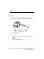
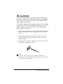
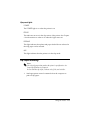
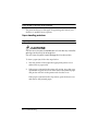
Unpacking
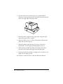
Your printer box should include these items. If any items are
damaged or missing, please contact your dealer for assistance.
Ribbon
Paper roll
Instruction label for
Hexagonal
when paper roll cover
lock screws
cannot be opened
These screws are used
only for the serial interface
Switch
cover
See the note on page 1-4 for information about the hexagonal lock screws.
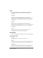
Note:
When you lift the printer, be sure to hold the bottom of the
printer to prevent damage.
Setting Up the Printer 1-1
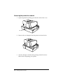
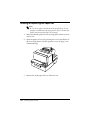
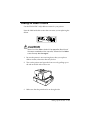
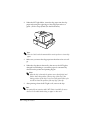
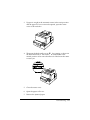
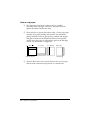
Removing the protective material
1. Open the printer by pulling up on the tab on the front cover.
Tab
2. Remove the two dampers from the printer as shown below.
3. Store the dampers with the other packing materials and use
them when transporting your printer.
1-2 Setting Up the Printer
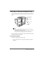
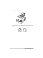
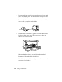
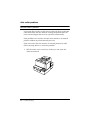
Connecting the Cables and Grounding the Printer
You can connect up to five cables to the printer. They all connect to
the connector panel on the bottom of the printer, which is shown
below:
Grounding screw
Power supply
Drawer kick-out
Display module
Interface
Note:
There are caution labels beside the drawer kick-out connector
and the display module connector.
Depending on the interface installed, the interface connector on
your printer may look different from the one illustrated.
Before connecting any of the cables, make sure that both the printer
and the computer are turned off.
Connecting the computer
You need an appropriate interface cable.
1. Plug the cable connector securely into the printer’s interface
connector.
Setting Up the Printer 1-3
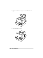
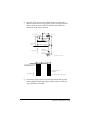
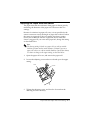
2. Tighten the screws on both sides of the cable connector.
Note:
Your printer has inch-type hexagonal lock screws installed. If
your interface cable requires millimeter-type screws, replace the
inch-type screws with the enclosed millimeter-type screws using
a hex screwdriver (5 mm).
Inch screw
Millimeter screw
3. Attach the other end of the cable to the computer.
1-4 Setting Up the Printer
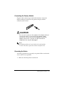
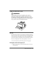
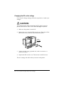
Connecting the Drawer
WARNING:
Use a drawer that matches the printer specification. Using an
improper drawer may damage the drawer as well as the
printer.
CAUTION:
Do not connect a telephone line to the drawer kick-out
connector; otherwise the printer and the telephone line may
be damaged.
Plug the drawer cable into the drawer kick-out connector on the
bottom of the printer next to the power supply connector.
Setting Up the Printer 1-5
Anschließen der Lade
WARNUNG:
Eine für den Drucker geeignete Lade verwenden. Bei
Verwendung einer falschen Lade kann diese oder der
Drucker beschädigt werden.
ACHTUNG:
Kein Telefonkabel an die Schnappsteckerbuchse
anschließen, da sonst der Drucker und die Telefonkabel
beschädigt werden können.
Das Kabel der Lade an die Schnappsteckerbuchse unten am
Drucker neben dem Netßzanschluß anschließen.
1-6 Setting Up the Printer
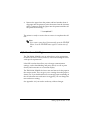
Connecting the Display Module
Plug the cable connector (provided with the direct connection
display module) securely into the printer’s display module
connector until it clicks.
CAUTION:
Be sure not to connect this cable to the drawer kick-out
connector, which is to the left of the power supply
connector. Do not connect a telephone line to the
display connector. If you do, the printer and the
telephone line may be damaged.
Notes:
The display module can be used only for the serial interface.
To remove the cable, squeeze the connector and pull it out.
Grounding the Printer
You need a ground wire to ground your printer. Make sure that the
wire is AWG 18 or equivalent.
1. Make sure that the printer is turned off.
Setting Up the Printer 1-7
2. Connect the ground wire to the printer using the FG screw on
the bottom of the printer, as shown.
Connecting the Power Supply
Use the optional EPSON PS-170 or equivalent power supply for
your printer.
WARNING:
Make sure that you use the EPSON PS-170 power supply or
equivalent. Using an incorrect power supply may cause fire or
electrical shock.
1-8 Setting Up the Printer
CAUTIONS:
When connecting or disconnecting the power supply from
the printer, make sure that the power supply is not plugged
into an electrical outlet. Otherwise you may damage the
power supply or the printer.
If the power supply’s rated voltage and your outlet’s voltage
do not match, contact your dealer for assistance. Do not
plug in the power cord. Otherwise you may damage the
power supply or the printer.
1. Make sure that the printer’s power switch is turned off, and the
power supply’s power cord is unplugged from the electrical
outlet.
2. Check the label on the power supply to make sure that the
voltage required by the power supply matches that of your
electrical outlet.
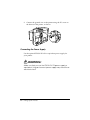
3. Plug in the power supply’s cable as shown below. Notice that
the flat side of the plug faces down.
Note:
To remove the DC cable connector, make sure that the power
supply’s power cord is unplugged; then grasp the connector at the
arrow and pull it straight out.
Setting Up the Printer 1-9
Installing or Replacing the Paper Roll
Note:
Be sure to use paper rolls that meet the specifications. Do not
use paper rolls that have the paper glued to the core because the
printer cannot detect the paper end correctly.
1. Make sure that the printer is not receiving data; otherwise, data
may be lost.
2. Open the paper roll cover by pressing the cover-open button. If
the cover-open button will not open the cover, see page 3-4 in
Troubleshooting.
3. Remove the used paper roll core if there is one.
1-10 Setting Up the Printer
4. Insert the paper roll as shown.
5. Be sure to note the correct direction that the paper comes off the
roll.
Setting Up the Printer 1-11
6. Pull out a small amount of paper, as shown. Then close the
cover.
7. Tear off the paper as shown.
1-12 Setting Up the Printer
Installing the Ribbon Cassette
Use the EPSON ERC-31(P) ribbon cassette for your printer.
Note the label inside this section that can assist you in replacing the
ribbon.
CAUTION:
Never turn the ribbon knob in the opposite direction of
the arrow marked on the cassette; otherwise the ribbon
cassette may be damaged.
1. Be sure the printer is not receiving data when you replace a
ribbon cassette; otherwise data may be lost.
2. Turn on the printer and open the front cover by pulling up on
the tab on the left side of the cover.
3. Make sure that the print head is on the right side.
Setting Up the Printer 1-13
4. If you are replacing a used ribbon, grasp the end of the tab and
remove it from the printer. See the illustration in step 5 for the
location of the tab.
5. Turn the ribbon knob two or three times in the direction of the
arrow to take up any slack in the ribbon.
Tab
6. Insert the ribbon cassette in the printer and rotate the cassette's
knob two or three more times. This is necessary to place the
ribbon in the correct position.
Knob
Make sure that the ribbon is installed below the print head
without wrinkles or creases. (See ➄ on the label for an
illustration of where the ribbon should go.)
If the ribbon is not installed correctly, remove the cassette and
repeat steps 5 and 6 above.
1-14 Setting Up the Printer
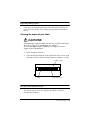
Using the Power Switch Cover
WARNING:
If an accident occurs when the power switch cover is
attached, unplug the power supply cord from the outlet
immediately. Continued usage may lead to fire or shock.
You can use the enclosed power switch cover to make sure that the
power switch is not accidentally pressed. If you want to use this
cover, install it as shown in the illustration below.
Self Test
The self test lets you know if your printer is operating properly. It
checks the control circuits, printer mechanisms, print quality, ROM
version, and DIP switch settings. (It also checks the MICR reader
circuits if the printer is equipped with the optional MICR reader.)
This test is independent of any other equipment or software.
You can run the self test with either paper roll or slip paper.
Running the self test with a paper roll
1. Make sure the printer is turned off and the printer covers are
closed properly.
Setting Up the Printer 1-15
2. While holding down the FEED button, turn on the printer using
the switch on the front of the printer to begin the self test. The
self test prints the printer settings and then prints the
following, cuts the paper, and pauses. (The PAPER OUT light
blinks.)
Self test printing.
Please press the PAPER FEED button.
3. Press the FEED button to continue printing. The printer prints a
pattern using the built-in character set.
4. The self test automatically ends and cuts the paper after
printing the following:
*** completed ***
The printer is ready to receive data as soon as it completes the self
test.
Note:
If you want to pause the self test manually, press the FEED
button. Press the FEED button again to continue the self test.
Running the self test with slip paper
1. Make sure the printer is turned off and the printer cover is
closed properly.
2. While holding down the REVERSE button, turn on the printer to
begin the self test. (The SLIP light blinks.)
3. Feed a sheet of slip paper into the printer. The printer loads the
paper automatically, prints the printer settings, and then ejects
the paper.
1-16 Setting Up the Printer
4. Remove the paper from the printer and feed another sheet of
slip paper into the printer to print characters from the character
table. Continue to feed slip paper into the printer until the self
test prints the following:
***completed***
The printer is ready to receive data as soon as it completes the self
test.
Note:
If you want to pause the self test manually, press the REVERSE
button. Press the REVERSE button again to continue the self
test.
Adjustments and Settings
The TM-H5000/H5000P is set up at the factory to be appropriate
for almost all users. It does, however, offer some settings for users
with special requirements.
It has DIP switches that allow you to change communication
settings, such as handshaking and parity check, as well as print
density and connection to a customer display.
The TM-H5000/H5000P also has a near-end sensor for the paper in
the receipt section. This can give you a warning when the paper is
almost out. If you find that there is not enough paper remaining on
the roll when the near-end sensor is triggered, you can change the
near-end sensor setting.
See Appendix A if you need to make any of these changes.
Setting Up the Printer 1-17
1-18 Setting Up the Printer
Chapter 2
Using the Printer
Operating the Control Panels
You can control the basic paper feeding operations of the printer
with the buttons on the control panels. The indicator lights help
you monitor the printer’s status.
Paper Roll Control Panel
POWER
ERROR
PAPER
OUT
FEED
Button
The button can be disabled by the ESC c 5 command, but it works
whenever the printer cover is open, even if it has been disabled by
the ESC c 5 command.
Press the FEED button once to advance receipt paper one line. You
can also hold down the FEED button to feed receipt paper
continuously.
Slip Control Panel
FORWARD
REVERSE
POWER
ERROR
RELEASE
SLIP
RELEASE
Using the Printer 2-1
Buttons
The printer and these buttons will not operate when the cover is
open. Also these buttons can be disabled with the ESC c 5
command.
FORWARD
When the printer is in the slip mode (the SLIP light is on or
blinking), press the FORWARD button once to advance slip paper
one line. You can also hold down this button to feed slip paper
continuously.
REVERSE
When the printer is in the slip mode (the SLIP light is on or
blinking), press the REVERSE button once to reverse slip paper one
line. You can also hold down this button to reverse slip paper
continuously.
RELEASE
When the printer is in the slip mode (the SLIP light is on or
blinking), press this button to release slip paper.
Indicator lights
The control panel lights provide information on printer conditions.
Paper roll panel lights
POWER
The POWER light is on whenever the printer is on.
ERROR
This indicates an error in the paper roll section of the printer. See
Chapter 3 for information on what to do when this light comes on.
PAPER OUT
This light indicates either the end or the near end of the paper roll.
Install a new paper roll and the printer will continue printing.
2-2 Using the Printer
Slip panel lights
POWER
The POWER light is on when the printer is on.
ERROR
This indicates an error in the slip section of the printer. See Chapter
3 for information on what to do when this light comes on.
RELEASE
This light indicates that platen and paper feed roller are released so
that slip paper can be inserted.
SLIP
This light indicates that the printer is in the slip mode.
Slip Paper Handling
Notes:
Use only slip paper that matches the printer’s specifications. See
Paper Specifications in Chapter 4.
Be sure that the slip is flat, without curls, folds, and wrinkles.
1. Send appropriate control commands from the computer to
print on slip paper.
Using the Printer 2-3
2. When the SLIP light blinks, insert the slip paper into the slip
paper inlet using the right edge of the slip paper inlet as a
guide. (Follow steps ➀ and ➁ in the illustration.)
1
2
Note:
There is a label on the document table to assist you how to insert slip
paper.
3. Make sure you insert the slip paper into the inlet as far as it will
go.
4. When the slip sheet is detected by the sensor, the SLIP light is
changed from blinking to on and the paper is automatically
drawn into the printer and printing begins.
Note:
After the slip is detected, the printer moves the slip back and
forth to detect the position of the top edge of the slip. If the
setting position of the slip is not correct, the printer takes a few
seconds to detect the position of the top edge of the slip.
5. After printing when the SLIP light is off, remove the slip.
Note:
An optional front extension table (WT-5000) is available for users
who need it to enable handwriting on paper or other uses.
2-4 Using the Printer
Using the MICR Reader (Option)
If your printer has the factory installed optional Magnetic Ink
Character Recognition (MICR) reader that enables the printer to
read and process MICR characters on personal checks, read this
section.
Reading MICR characters on personal checks
To use the MICR function with personal checks, follow the steps
below:
CAUTION:
Do not insert checks with staples in them. This may cause
paper jams, MICR reading errors, and damage to the MICR
head.
Note:
Be sure that the checks are flat, without curls, folds, or wrinkles.
1. Wait until the computer sends the FS a 0 command to the
printer, causing it to enter the MICR mode. The SLIP light
blinks.
Using the Printer 2-5
2. Turn the check over so that it is face down with the MICR
characters on the right-hand side. The MICR characters must be
next to the right edge of the paper inlet.
3. Insert the check straight into the paper inlet, using the right
edge of the paper inlet as a guide.
4. Insert the check as far as it will go. The printer will detect the
check and start drawing it in.
5. When the printer starts drawing it in, let go of the check
immediately. The SLIP light quits blinking but stays on.
6. When printing and MICR reading are finished, the printer
ejects the check and the SLIP light starts blinking again.
7. Remove the check by pulling it straight up; do not pull it at an
angle. The SLIP light goes off.
See Chapter 3 to find out how to clean the MICR mechanism.
2-6 Using the Printer
Chapter 3
Troubleshooting
Troubleshooting
This chapter gives solutions to some printer problems you may
have.
General problems
The lights on the control panel do not come on.
Make sure that the power supply cables are correctly plugged into
the printer, the power unit, and to the power outlet.
Make sure that power is supplied to the power outlet. If the outlet
is controlled by a switch or timer, use another outlet.
Printing problems
The paper roll section ERROR light is on (not blinking) and nothing is
printed.
If the PAPER OUT light is on, the paper roll is not installed or is at
or near the end. Install a new paper roll. See Chapter 1 for
instructions.
If the PAPER OUT light is off, make sure that the paper roll cover is
properly closed. Press the printer cover until the cover audibly
clicks into place.
An ERROR light is blinking and the printer does not print.
First, turn off the printer and check for a paper jam. (See the paper
jam description on page 3-4.)
Troubleshooting 3-1
If there is no paper jam and the printer has been printing for quite a
while, the print head may be overheated. If the print head is
overheated, the printer will resume printing when the head has
cooled (usually within two or three minutes).
If there is no paper jam and the print head is not overheated, turn
off the printer and turn it back on after about 10 seconds. If the
ERROR light is still flashing, contact a qualified service person.
The ERROR light is off, but nothing is printed.
Try to run the self test to check that the printer works properly. See
the self test instructions in Chapter 1 to run the self test. If the self
test does not work, contact your dealer or a qualified service
person.
If the self test works properly, check the following:
1. Check the connection at both ends of the interface cable
between the printer and the computer. Also make sure that this
cable meets the specifications for both the printer and the
computer.
2. The data transmission settings may be different between the
printer and computer. Make sure that the printer’s DIP switch
settings for data transmission are the same as the computer’s.
You can print the printer’s interface settings using the self test.
If the printer still does not print, contact your dealer or a qualified
service person.
The slip section of the printer sounds like it is printing, but nothing is
printed.
The ribbon cassette may not be installed properly. See the
instructions in Chapter 1.
The ribbon may be worn out. Replace the ribbon cassette as
described in Chapter 1.
3-2 Troubleshooting
Paper roll printing is poor.
Paper dust on the heating element of the thermal print head can
lower the print quality. Try cleaning the print head as described
below:
Cleaning the paper roll print head
CAUTIONS:
After printing, the print head can be very hot. Be careful not
to touch it. Also let it cool before you clean it.
Do not damage the print head by touching it with your
fingers or any hard object.
1. Open the paper roll cover.
2. Clean the thermal element of the print head with a cotton swab
moistened with an alcohol solvent (ethanol, methanol, or IPA).
Radiation plate
Head
Thermal element
The slip section printout is faint.
The ribbon may be worn out. Replace the ribbon cassette as
described in Chapter 1.
Troubleshooting 3-3
A line of dots is missing in the printout.
The print head may be damaged. Stop printing and contact your
dealer or a qualified service person.
Paper handling problems
Paper is jammed inside the printer.
CAUTIONS:
Do not touch the print head because it can be very hot after
printing continuously for a long time.
Do not move the print head carriage for the slip section.
To clear a paper jam, follow the steps below:
1. Turn the printer off and open the appropriate printer cover
(either front or paper roll).
2. If the paper is jammed in the paper roll section, press the cover
open button to open the cover. Then remove the jammed paper
and put the roll back in the printer and close the cover.
If the paper is jammed in the slip section, open the front cover
and remove the jammed paper.
3-4 Troubleshooting
3. If paper is caught in the automatic cutter in the receipt section
and the paper roll cover cannot be opened, open the cutter
cover as shown below.
4. Then turn the knob until you see in the opening, as shown in
the illustration below. This returns the cutter blade to the
normal position. Also notice that there is a label near the cutter
to assist you.
5. Close the cutter cover.
6. Open the paper roll cover.
7. Remove the jammed paper.
Troubleshooting 3-5
Auto cutter problems
The auto cutter is jammed.
If a foreign object such as a push pin or paper clip drops in the auto
cutter and causes the auto cutter to lock up, the printer enters an
error state and begins the recovery operation automatically.
If the problem is not serious, the auto cutter returns to its normal
position without any intervention by the user.
If the auto cutter does not return to its normal position by itself,
follow the steps below to correct the problem:
1. Pull the cutter cover toward you so that you can rotate the
cutter motor knob.
3-6 Troubleshooting
2. Following the instructions on the label, rotate the knob until the
appears in the hole.
3. Close the cutter cover.
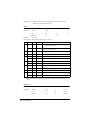
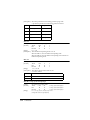
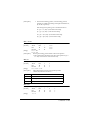
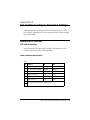
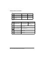
Cleaning the Optional MICR Mechanism
MICA cleaning method (Recommended)
Cleaningpoint
Use cleaning sheet
Frequency
MICR head department
Moistened Cleaning
sheet
6000 times or for one
month
MICA system department
Adhensive cleaning sheet
6000 times or for one
month
* Combine these 2 procedures, if you encounter frequent MICR reading errors.
The cleaning procedure
During in the self test mode
1) Confirm to set a roll paper and a ribbon cassette to make use a
printer mechanism properly.
Troubleshooting 3-7
2) Turn off the power switch.
3) Open a front cover(rid).
4) Turn on the power switch while turning on “JOURNAL/
SLIP FEED button.
5) Push “JOURNAL/SLIP FEED” button 3 times.
6) Close a SLIP front cover (rid).
7) Following message will be printed on receipt paper and
“SLIP” LED flushes.
****** WAVEFORM TRANSMISSION MODE
*****
Please set back
8) Peel off the pasteboard portion of a designated point of a
cleaning sheet.
* This procedure, 8) , is required only for an adhesive
cleaning sheet.
3-8 Troubleshooting
9) As a check paper, insert a cleaning sheet into a printer,
* Set yellow non-stick side to be upside when cleaning using
adhesive sheet.
10) Remove and do a sheet after cleaning sheet discharge.
11) Turn off the power switch.
Command code sequence
1) MICA cleaning command <FS c> was installed to clean up.
2) Carry out from 8) to 10) described above in the self test mode.
NOTES
In case of using an adhesive cleaning sheet,
1) peel off only desinated pasteboard.
2) insert from correct derection, and
3) insert as peeled portion to be upside.
Explanatin of a cleaning sheet
Moistened Cleaning sheet
PRESAT brand (KIC) “CHECK READER CLEANING CARD” or
equivalent cleaning sheet is required.
Adhesice cleaning sheet (Refer to Figure 2)
Part Name : Sheet roller cleaning, A
Part Number : 1038046
Troubleshooting 3-9
Hexadecimal Dump
This feature allows experienced users to see exactly what data is
coming to the printer. This can be useful in finding software
problems. When you turn on the hex dump function, the printer
prints all commands and other data in hexadecimal format along
with a guide section to help you find specific commands.
To use the hex dump feature, follow these steps:
1. After you make sure that the printer is off, open the cover.
2. Hold down the FEED button while you turn on the printer.
3. Close the cover.
4. Run any software program that sends data to the printer. The
printer prints “Hexadecimal Dump” and then all the codes it
receives in a two-column format. The first column contains the
hexadecimal codes and the second column gives the ASCII
characters that correspond to the codes.
Hexadecimal Dump
1B 21 00 1B 26 02 40 40 . ! . . & . @ @
1B 25 01 1B 63 34 00 1B . % . . c4 . .
41 42 43 44 45 46 47 48 ABCDEFGH
❏
A period (.) is printed for each code that has no ASCII
equivalent.
❏ During the hex dump all commands except DLE EOT and
DLE ENQ are disabled.
5. Open the cover to set the printer off line so that it will print the
last line.
6. Close the cover and turn off the printer or reset it to turn off the
hex dump mode.
3-10 Troubleshooting
Chapter 4
Reference Information
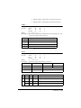
Printing Specifications
Slip Paper
Printing method:
Serial impact dot matrix
Head wire
configuration:
9-pin vertical line, 0.353 mm (1/72-inch)
wire pitch
Head wire diameter:
0.29 mm (.01")
Printing direction:
Bidirectional, minimum distance printing
Number of characters: Alphanumeric characters: 95
International characters: 32
Extended graphics: 128 × 7 pages
(including space page)
Character structure:
Font A: 9 × 9, 3-dot spacing (in half-dot
units)
Font B: 7 × 9, 2-dot spacing (in half-dot
units)
Larger spacing can be set by using ESC SP.
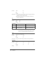
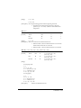
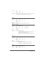
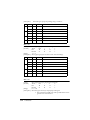
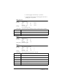
Character size and printing speed
Character
structure
(Horizontal
dots × vertical
dots)
Character
spacing
(half dots)
Characters
per inch
Characters
per second
(carriage
moving speed)
Characters
per line
Character size
(width×height)
9×9
3 dots
12.5
233
66
1.6 × 3.1 mm
(.06" × .12")
7×9
2 dots
16.7
311
88
1.3 × 3.1 mm
(.05" × .12")
Reference Information 4-1
Receipt Paper
Printing method:
Thermal line printing
Dot density:
180 dpi × 180 dpi [the number of dots per
25.4 mm (1”)]
Printing direction:
Unidirectional with friction feed
Printing width:
72 mm (2.83”), 512 dot positions
Characters per line:
42 (Font A) (default)
56 (Font B)
Character spacing:
0.28 mm (.01”) (2 dots) (Font A)(default)
0.28 mm (.01”) (2 dots) (Font B)
Programmable by control command.
Printing speed - High: Approximately 16.5 lines/second
(4.23 mm (1/6”) feed, at 24V, 20° C,
density level 2)
Approximately 70 mm/second
(approximately 2.76”/second)
Printing speed - Low:
Approximately 11.8 lines/second (4.23
mm (1/6”) feed)
Approximately 50 mm/second
(approximately 2.0”/second)
High and low speeds are switched
automatically depending on the voltage
applied to the printer and the temperature
of the environment.
Approximately 35 mm/second
(approximately 1.4”/second) when a
ladder bar code is printed.
Note:
Printing speed may be slower, depending on the data transmission
speed and the combination of control commands.
4-2 Reference Information
Approximately 70 mm/second
(approximately 2.76”/second) continuous
printing
Paper feeding speed:
Line spacing (default): 4.23 mm (1/6”)
Programmable by control command.
Number of characters: Alphanumeric characters: 95
International characters: 32
Extended graphics: 128 × 10 pages
(including one space page)
Font A: 12 × 24 (including 2-dot spacing
in horizontal)
Character structure:
Font B: 9 × 24 (including 2-dot spacing in
horizontal)
Font A is the default
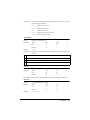
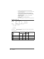
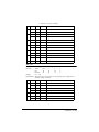
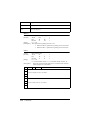
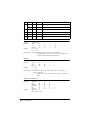
Character size, characters per line
Standard
Double-height
Double-width
Double-width/
Double-height
WxH
(mm)
CPL
WxH
(mm)
CPL
WxH
(mm)
CPL
WxH
(mm)
CPL
Font A
12 x 24
1.41 x 3.39
(.06” x .13”)
42
1.41 x 6.77
(.06” x .27”)
42
2.82 x 3.39
(.11” x .13”)
21
2.82 x 6.77
(.11” x .27”)
21
Font B
9 x 24
0.99 x 3.39
(.04” x .13”)
56
0.99 x 6.77
(.04” x .27”)
56
1.98 x 3.39
(.08” x .13”)
28
1.98 x 6.77
(.08” x .27”)
28
* CPL = Characters Per Line
* Space between characters is not included
* Characters can be scaled up to 64 times as large as the standard sizes.
Reference Information 4-3
Ribbon Specifications
Type:
Exclusive cassette ribbon
Ribbon cassette
specifications:
Part number: ERC-31 (P), ERC-31(B)
Color:
(P) Purple, (B) Black
Ribbon life:
(P) 7,000,000 characters
(B) 4,500,000 characters
(when 1 character=18 dots)
MICR Reader (Option)
The MICR reader is a factory-installed option.
Available fonts:
E-13B, CMC7
Reading method:
Magnetic bias
Recognition rating:
98% or more at 25°C (75°F)
Rating = ([total checks – number misread
or not identified]/total checks) × 100
Check paper tested is EPSON standard
check paper. Checks must be flat, without
curls, folds, or wrinkles. The magnetic bias
method is used for reading.
Paper type:
Normal check paper with thickness of 0.09
to 0.36 mm (0.0035 to 0.141”)
Size: 70 mm × 70 mm to 210 mm × 297 mm
(A4) (2.76” × 2.76” to 8.27” × 11.69”)
4-4 Reference Information
Paper Specifications
Paper feed method:
Friction feed
Paper feed pitch:
Default 4.23 mm (1/6”)
Paper feed speed:
Slip:
Approximately 60.3 msec/line
(4.23 mm (1/6”) feeding)
Approximately 86.4 mm/second (3.4
inches/second) (continuous feeding)
Paper roll:
Approximately 70 mm/second (2.76
inches/second) (continuous feeding)
Paper roll (single-ply): Size:
Width: 79.5 mm ± 0.5 mm
(3.13” ± 0.02”)
Maximum
outside
diameter:
83 mm (3.27”)
Paper roll
spool
diameter:
Inside: 12 mm (0.47”)
Outside: 18 mm (0.71”)
Paper must not be pasted
to the paper roll spool.
Take up
paper roll
width:
0.02
80± 0.5
1.0 mm 3.15± 0.04
Reference Information 4-5
Slip paper
Paper type:
Normal paper
Carbon copy paper
Pressure sensitive paper
Total
thickness:
0.09 to 0.36 mm (.0035 to
.0141”)
See “Copy capability and paper thickness”
on the next page for more information.
Size
(W × L):
Ambient temperature
and copy capability
70 mm × 70 mm to 210 mm
× 297 mm (A4)
(2.76” × 2.76”to 8.27” ×
11.69”)
Copy capability is greatly influenced by
the ambient temperature, so printing must
be performed under the conditions
described in the table below.
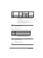
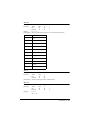
Relationship between ambient temperature and
number of copies
Number of copies
Ambient temperature (print mode)
Original + 4 copies
Approx. 20° to 45°C (68° to 113°F)
Original + 1 to 3 copies
5° to 45°C (41° to 113°F)
4-6 Reference Information
Copy capability and
paper thickness:
Normal paper (single-ply): 0.09 to 0.2 mm
(.0035 to .0079”)
Carbon copy paper combination:
5 sheets maximum (original + 4 copies) at
20° to 45°C (68° to 113°F)
Backing paper:
0.06 to 0.15 mm (.0023 to .0059”)
Copy and original:
0.04 to 0.07 mm (.0015 to .0028”)
Carbon paper:
Approximately 0.035 mm (.0014”)
Total thickness:
0.30 mm (.0118”) or less (for any
combination, from a single original to an
original + 3 copies)
0.36 mm (.0141”) or less (for any
combination, from a single original to an
original + 4 copies)
Pressure sensitive paper:
5 sheets maximum (original + 4 copies) at
20° to 45°C (68° to 113°F)
Backing paper:
0.06 to 0.15 mm (.0023 to .0059”)
Copy and original:
0.06 to 0.075 mm (.0023 to .003”)
Total thickness:
0.24 mm (.0094”) or less (original to
original + 3 copies)
0.30 mm (.0118”) or less (original + 4
copies)
Note:
When using multi-ply paper that consists of an original and three or
four copies, be sure to print with a 9 × 9 font. If a 7 × 9 font is used,
some characters on some of the copies may not be readable.
Reference Information 4-7
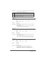
Notes on slip paper
❏ The slip paper must be flat, without curls or wrinkles,
especially at the top edges. Otherwise, the paper may rub
against the ribbon and become dirty.
❏ There must be no glue on the bottom edge. Choose slip paper
carefully since paper feeding and insertion are affected by
gluing conditions (such as glue quality, method, and length)
and glue location (see the illustration below). Be especially
careful when slip paper is wide and has glue on the left edge,
since it may not feed in a straight line.
.
OK to use
Paper feed direction
Do not use
Use carefully
OK to use
Glued area
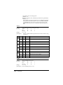
❏ Since the BOF sensor uses a photo detector, do not use paper
that has holes at the detector position, or is translucent.
4-8 Reference Information
❏ Since the TOF sensor uses a reflective photo sensor and it
detects from the back of slip paper, do not use paper that has
holes or dark portions with low reflection (less than 40%
reflection) at the sensor position.
31
8
Form stopper position
18.9
MICR head
1.8
1.3
TOF sensor
position
38.5
18
39
37.2
Center of the print head
Slip feeding roller
position
21.9
Slip side guide
Paper feed direction
BOF sensor
3.6
[ All the numeric values are typical. ]
15
24
10
Area where paper holes are prohibited
and reflection rate for the back of
paper should be 40% or more.
Paper holes and translucence
prohibited area.
Paper feed direction
[Units: mm (All the numeric values are typical.)]
❏ Use thinner paper (N30 or equivalent) between the top and
bottom sheets of multi-ply paper. If thick paper is used, the
copy capability is lowered.
Reference Information 4-9
Electrical Characteristics
Supply voltage:
+24 VDC ± 10% (optional power supply: EPSON
PS-170)
Ripple
voltage:
300mVpp or less (only when the
printer is used with the MICR
reader).
Operating: Mean: approximately 1.9A
Current
(character font A α-N all columns
consumption: (at Slip
printing)
24V, except for
Peak: approximately 8.0A (20 msec)
drawer kick-out
When the print platen is released:
driving)
2.0A (200 msec)
Operating: Mean: approximately 1.5A
Receipt
(character font A α-N all columns
printing)
Peak: Approximately 5.0A (20 msec)
Standby:
Mean: approximately 0.3A
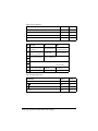
Reliability
Slip:
Mechanism:
Life (when
printing
alphanumeric
characters):
Print head:
4-10 Reference Information
12,000,000 lines
150 million characters
(when in the average of
2 dots/wire per
character)
240,000 passes
The MICR reader is
defined to have
reached the end of its
life when it reaches the
beginning of the
Wearout Period.
MICR reader
mechanism (only
when the printer
is used with the
MICR reader):
MTBF:
180,000 hours
Failure is defined
as Random
Failure occurring
at the time of the
Random Failure
Period.
MCBF:
29,000,000 lines
This is an average
failure interval
based on failures
relating to
wearout and
random failures
up to the life of 12
million lines.
Receipt:
Life:
Mechanism:
15,000,000 lines
Thermal head:
100 million pulses,
100 km
Auto cutter:
1,500,000 cuts
MTBF:
180,000 hours
MCBF:
37,000,000 lines
Reference Information 4-11
Environmental Conditions
Temperature:
Humidity:
4-12 Reference Information
Operating:
5° to 45°C (41° to 113°F)
Storage:
-10° to 50°C (14° to 122°F)
(except for paper)
Operating:
10 to 90% RH
Storage:
10 to 90% RH (except for
paper)
Chapter 5
Commands
Command Notation
[Name]
[Format]
The name of the command.
The code sequence.
ASCII indicates the ASCII equivalents.
Hex indicates the hexadecimal equivalents.
Decimal indicates the decimal equivalents.
[ ]k indicates the contents of the [ ] should be repeated k times.
[Range]
Gives the allowable ranges for the arguments.
[Description] Describes the function of the command.
Explanation of Terms
LSB
Least Significant Bit
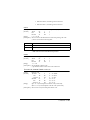
Control Commands
HT
[Name]
[Format]
Horizontal tab
ASCII
HT
Hex
09
Decimal
9
[Description] Moves the print position to the next horizontal tab position.
LF
[Name]
[Format]
Print and line feed
ASCII
LF
Hex
0A
Decimal
10
[Description] Prints the data in the print buffer and feeds one line based on the current
line spacing.
FF
[Name]
➀ Print and eject cut sheet (in standard mode)
➁ Print and return to standard mode (in page mode)
Commands 5-1
[Format]
ASCII
FF
Hex
0C
Decimal
12
[Description] ➀ Prints the data in the print buffer and ejects the slip paper (when the
slip paper is selected as the print sheet).
➁ In page mode, prints the data in the print buffer collectively and
returns to standard mode.
CR
[Name]
[Format]
Print and carriage return
ASCII
CR
Hex
0D
Decimal
13
[Description]
Paper
Automatic line feed enabled
Automatic line feed disabled
Paper roll
Functions as same as LF
Ignored
Slip paper
Functions as same as LF
Prints the data in the print buffer
and does not feed the paper.
• This command is ignored with a serial interface.
• This command is set according to the DIP switch 1-1 setting at
power-on or resetting the printer with a parallel interface .
CAN
[Name]
Cancel print data in page mode
[Format]
ASCII
CAN
Hex
18
Decimal
24
[Description] In page mode, deletes all the print data in the current printable area.
DLE EOT n
[Name]
Real-time status transmission
[Format]
ASCII
DLE
EOT
n
Hex
10
04
n
Decimal
16
4
n
[Range]
5-2 Commands
1 ≤n ≤5
[Description] Transmits the selected printer status specified by n in real time, according
to the following parameters:
n = 1:
Transmit printer status
n = 2:
Transmit off-line status
n = 3:
Transmit error status
n = 4:
Transmit paper roll sensor status
n = 5:
Transmit slip paper status
DLE ENQ n
[Name]
Real-time request to printer
[Format]
ASCII
DLE
ENQ
n
Hex
10
05
n
Decimal
16
5
n
[Range]
1 ≤n ≤ 3
[Description] Responds to a request from the host computer. n specifies the request as
follows:
n
Request
1
Recover from an error and restart printing from the line where the error occurred
2
Recover from an error after clearing the receive and print buffers
3
Cancel the slip waiting status
ESC FF
[Name]
[Format]
Print data in page mode
ASCII
ESC
FF
Hex
1B
0C
Decimal
27
12
[Description] In page mode, prints all buffered data in the printing area collectively.
ESC SP n
[Name]
Set right-side character spacing
[Format]
ASCII
ESC
SP
n
Hex
1B
20
n
Decimal
27
32
n
[Range]
0 ≤ n ≤ 255
Commands 5-3
[Description]
Sets the character spacing for the right side of the character to [n ×
horizontal or vertical motion units].
ESC ! n
[Name]
Select print mode(s)
[Format]
ASCII
ESC
!
n
Hex
1B
21
n
Decimal
27
33
n
[Range]
0 ≤ n ≤ 255
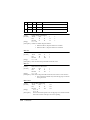
[Description] Selects print mode(s) using n as follows:
Bit
Off/On
Hex
Decimal
Function
Off
00
0
Character font A (12 x 24 for the paper roll and 9 x 9
for the slip paper) selected.
On
01
1
Character font B (9 x 24 for the paper roll and 7 x 9
for the slip paper) selected.
1
-
-
-
Undefined.
2
-
-
-
Undefined.
Off
00
0
Emphasized mode not selected.
On
08
8
Emphasized mode selected.
Off
00
0
Double-height mode not selected.
On
10
16
Double-height mode selected.
Off
00
0
Double-width mode not selected.
On
20
32
Double-width mode selected.
-
-
-
Undefined.
0
3
4
5
6
Off
00
0
Underline mode not selected.
On
80
128
Underline mode selected.
7
• Determine the values of n by adding the values of all the characteristics you want to
select.
ESC $ nL nH
[Name]
Set absolute print position
[Format]
ASCII
ESC
$
nL nH
Hex
1B
24
nL nH
Decimal
27
36
nL nH
5-4 Commands
[Range]
0 ≤ nL ≤ 255
0 ≤ nH ≤ 255
[Description] Sets the print starting position from the beginning of the line.
• The distance from the beginning of the line to the print
position is [(nL + nH × 256) × (vertical or horizontal motion
unit)] inches.
ESC % n
[Name]
[Format]
Select/cancel user-defined character set
ASCII
ESC
%
n
Hex
1B
25
n
Decimal
27
37
n
[Range]
0 ≤ n ≤ 255
[Description] Selects or cancels the user-defined character set.
• When the LSB is 0, the user-defined character set is canceled
and the internal character set is selected.
• When the LSB is 1, the user-defined character set is selected.
ESC & y c1 c2 [x1 d1...d(y × x1)]...[xk d1...d(y × xk)]
[Name]
[Format]
Define user-defined characters
ASCII
ESC
&
Hex
1B
26
Decimal
27
38
y c1 c2 [x1 d1...d(y × x1)]...
[xk d1...d(y × xk)]
y c1 c2 [x1 d1...d(y × x1)]...
[xk d1...d(y × xk)]
y c1 c2 [x1 d1...d(y × x1)]...
[xk d1...d(y × xk)]
[Range]
(For the paper roll)
y=3
32 ≤ c1 ≤ c2 ≤ 126
0 ≤ x ≤ 12 Font A (12 × 24)
0 ≤ x ≤ 9 Font B (9 × 24)
0 ≤ d1 ... d(y × xk) ≤ 255
(For slip paper)
y=2
32 ≤ c1 ≤ c2 ≤ 126
0 ≤ x ≤ 12 Font A (9 × 9)
0 ≤ x ≤ 9 Font B (7 × 9)
0 ≤ d1 ... d(y × xk) ≤ 255
[Description]
Defines user-defined characters.
Commands 5-5
• y specifies the number of bytes in the vertical direction.
• c1 specifies the beginning character code for the definition, and
c2 specifies the final code.
• x specifies the number of dots in the horizontal direction.
• d is the dot data for the characters. The dot pattern is in the
horizontal direction from the left side. Any remaining dots on
the right side are blank.
• The allowable character code range is from ASCII code
20H(32) to 7EH(126).
• The data to define a user-defined character is
(y × x) bytes.
• Set a corresponding bit to 1 to print a dot or 0 to not print a dot.
ESC ✻ m nL nH d1 ... dk
[Name]
[Format]
Select bit-image mode
m nL nH d1 ... k
ASCII
ESC
✻
m nL nH d1 ... k
Hex
1B
2A
m nL nH d1 ... k
Decimal
27
42
m = 0, 1, 32, 33 (for the paper roll)
[Range]
m = 0, 1 (for the slip paper)
0 ≤ nL ≤ 255
0 ≤ nH ≤ 3
0 ≤ d ≤ 255
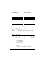
Selects a bit-image mode using m for the number of dots specified by
nL and nH, as follows:
(For the paper roll)
[Description]
Vertical Direction
Horizontal
direction
Number of
Bits
Dot
Density
Dot
Density
m
Mode
0
8-dot single-density
8
60 DPI
90 DPI
nL + nH × 256
1
8-dot double-density
8
60 DPI
180 DPI
nL + nH × 256
32
24-dot single-density
24
180 DPI
90 DPI
(nL + nH × 256) × 3
33
24-dot double-density
24
180 DPI
180 DPI
(nL + nH × 256) × 3
5-6 Commands
Number of Data (K)
(For slip paper)
Mode
Number of
Bits for
Vertical
Data
Horizontal Direction
m
Dot
Adjacency
Number
of Dots
0
8-dot single-density
8
Available
400
nL + nH × 256
1
8-dot double-density
8
Not available
800
nL + nH × 256
Number of Data
(K)
• The nL and nH indicate the number of dots of the bit image in
the horizontal direction. The number of dots is calculated by
nL + nH × 256.
• If the bit-image data input exceeds the number of dots to be
printed on a line, the excess data is ignored.
• d indicates the bit-image data. Set a corresponding bit to 1 to
print a dot or to 0 to not print a dot.
ESC - n
[Name]
[Format]
Turn underline mode on/off
n
ASCII
ESC
n
Hex
1B
2D
n
Decimal
27
45
[Range]
0 ≤ n ≤ 2, 48 ≤ n ≤ 50
[Description] Turns underline mode on or off, based on the following values of n:
n
Function
0, 48
Turns off underline mode
1, 49
Turns on underline mode (1-dot thick)
2, 50
Turns on underline mode (2-dots thick)
• If slip paper is selected, the underline is printed with 1-dot
thickness even if n is specified as 2 or 50.
ESC 2
[Name]
[Format]
Select default line spacing
ASCII
ESC
2
Hex
1B
32
Decimal
27
50
[Description] Sets the line spacing to 1/6 inch.
ESC 3 n
[Name]
Set line spacing
Commands 5-7
n
ASCII
ESC
3
n
Hex
1B
33
n
Decimal
27
51
[Range]
0 ≤ n ≤ 255
[Description] Sets the line spacing to [n × vertical or horizontal motion unit] inches.
[Format]
ESC <
[Name]
[Format]
Return home
ASCII
ESC
<
Hex
1B
3C
Decimal
27
60
[Description] Moves the print head to the standby position.
ESC = n
[Name]
[Format]
Set peripheral device
n
ASCII
ESC
=
n
Hex
1B
3D
n
Decimal
27
61
[Range]
1 ≤n ≤ 3
[Description] Selects device to which host computer sends data, using n as follows:
Bit
Off/On
Hex
Decimal
Function
Off
00
0
Printer disabled.
On
01
1
Printer enabled
Off
00
0
Customer display disabled.
On
02
2
Customer display enabled.
-
-
-
Undefined.
0
1
2-7
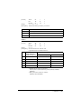
ESC ? n
[Name]
[Format]
Cancel user-defined characters
n
ASCII
ESC
?
n
Hex
1B
3F
n
Decimal
27
63
[Range]
32 ≤ n ≤ 126
[Description] Cancels user-defined characters.
ESC @
[Name]
Initialize printer
5-8 Commands
[Format]
ASCII
ESC
@
Hex
1B
40
Decimal
27
64
[Description]
Clears the data in the print buffer and resets the printer mode to the
mode that was in effect when the power was turned on.
ESC C n
[Name]
[Format]
Set cut sheet eject length
n
ASCII
ESC
C
n
Hex
1B
43
n
Decimal
27
67
[Range]
0 ≤ n ≤ 255
[Description] Sets the eject length setting for slip paper to n lines.
ESC D n1 ... nk NUL
[Name]
[Format]
Set horizontal tab positions
n1 ... nk NUL
ASCII
ESC
D
n1 ... nk 00
Hex
1B
44
n1 ... nk 0
Decimal
27
68
[Range]
1 ≤ n ≤ 255
0≤ k ≤ 32
[Description]
Sets horizontal tab positions.
• n specifies the column number for setting a horizontal tab
position from the beginning of the line.
• k indicates the total number of horizontal tab positions to be
set.
ESC E n
[Name]
[Format]
Turn emphasized mode on/off
n
ASCII
ESC
E
n
Hex
1B
45
n
Decimal
27
69
[Range]
0 ≤ n ≤ 255
[Description] Turns emphasized mode on or off
• When the LSB is 0, emphasized mode is turned off.
• When the LSB is 1, emphasized mode is turned on.
ESC F
[Name]
[Format]
Set/cancel cut sheet reverse eject
n
ASCII
ESC
F
n
Hex
1B
46
Commands 5-9
n
Decimal
27
70
[Range]
0≤ n ≤ 255
[Description] Sets or cancels the slip paper reverse eject
• When the LSB is 0, cancels the slip paper reverse eject and sets
the slip paper forward eject.
• When the LSB is 1, sets the slip paper reverse eject.
ESC G n
[Name]
[Format]
Turn double-strike mode on/off
n
ASCII
ESC
G
n
Hex
1B
47
n
Decimal
27
71
[Range]
0 ≤ n ≤ 255
[Description] Turns double-strike mode on or off.
• When the LSB is 0, double-strike mode is turned off.
• When the LSB is 1, double-strike mode is turned on.
ESC J n
[Name]
[Format]
Print and feed paper
n
ASCII
ESC
J
n
Hex
1B
4A
n
Decimal
27
74
[Range]
0 ≤ n ≤ 255
[Description] Prints the data in the print buffer and feeds the paper [n × vertical or
horizontal motion unit] inches.
ESC K n
[Name]
[Format]
Print and reverse feed
n
ASCII
ESC
K
n
Hex
1B
4B
n
Decimal
27
75
[Range]
0 ≤ n ≤ 255
[Description] Prints the data in the print buffer and feeds the paper n × vertical motion
unit inches in the reverse direction
This command is available only when the slip paper is selected as the print sheet.
ESC L
[Name]
[Format]
Select page mode
ASCII
ESC
L
Hex
1B
4C
Decimal
27
76
[Description] Switches from standard mode to page mode.
5-10 Commands
ESC R n
[Name]
[Format]
Select an international character set
n
ASCII
ESC
R
n
Hex
1B
52
n
Decimal
27
82
[Range]
0 ≤ n ≤ 10
[Description] Selects an international character set n from the following table:
n
Character set
0
U.S.A.
1
France
2
Germany
3
U.K.
4
Denmark I
5
Sweden
6
Italy
7
Spain
8
Japan
9
Norway
10
Denmark II
ESC S
[Name]
[Format]
Select standard mode
ASCII
ESC
S
Hex
1B
53
Decimal
27
83
[Description] Switches from page mode to standard mode.
ESC T n
[Name]
[Format]
[Range]
Select print direction in page mode
n
ASCII
ESC
T
n
Hex
1B
54
n
Decimal
27
84
0≤n≤3
48 ≤ n ≤ 51
Commands 5-11
[Description] Selects the print direction and starting position in page mode.
n specifies the print direction and starting position as follows:
n
Print Direction
Starting Position
0, 48
Left to right
Upper left
1, 49
Bottom to top
Lower left
2, 50
Right to left
Lower right
3, 51
Top to bottom
Upper right
ESC U n
[Name]
[Format]
Turn unidirectional printing mode on/off
n
ASCII
ESC
U
n
Hex
1B
55
n
Decimal
27
85
[Range]
0 ≤ n ≤ 255
[Description] Turns unidirectional printing mode on or off
When the LSB is 1, turns on unidirectional printing mode.
When the LSB is 0, turns off unidirectional printing mode and turns on
bidirectional printing mode.
ESC V n
[Name]
[Format]
Turn 90° clockwise rotation mode on/off
n
ASCII
ESC
V
n
Hex
1B
56
n
Decimal
27
86
n = 0, 1, 48, 49
[Range]
[Description] Turns 90° clockwise rotation mode on/off
n is used as follows:
n
Function
0, 48
Turns off 90° clockwise rotation mode
1, 49
Turns on 90° clockwise rotation mode
ESC W xL xH yL yH dxL dxH dyL dyH
[Name]
[Format]
[Range]
5-12 Commands
Set printing area in page mode
xL xH yL yH dxL dxH dyL dyH
ASC II
ESC
W
xL xH yL yH dxL dxH dyL dyH
Hex
1B
57
xL xH yL yH dxL dxH dyL dyH
Decimal
27
87
0 ≤ xL, xH, yL, yH, dxL, dxH, dyL, dyH ≤ 255
(except dxL=dxH=0 or dyL=dyH=0)
[Description]
• The horizontal starting position, vertical starting position,
printing area width, and printing area height are defined as x0,
y0, dX, dY, respectively.
Each setting for the printing area is calculated as follows:
x0 = [(xL + xH ( 256) × (horizontal motion unit)]
y0 = [(yL + yH ( 256) × (vertical motion unit)]
dx = [dxL + dxH ( 256) × (horizontal motion unit)]
dy = [dyL + dyH ( 256) × (vertical motion unit)]
ESC \ nL nH
[Name]
[Format]
Set relative print position
nL nH
ASCII
ESC
\
nL nH
Hex
1B
5C
nL nH
Decimal
27
92
[Range]
0 ≤ nL ≤ 255
0 ≤ nH ≤ 255
[Description]
Sets the print starting position based on the current position.
• This command sets the distance from the current position to [(nL +
nH × 256) × horizontal or vertical motion unit]
ESC a n
[Name]
[Format]
Select justification
n
ASCII
ESC
a
n
Hex
1B
61
n
Decimal
27
97
[Range]
0 ≤ n ≤ 2, 48 ≤ n ≤ 50
[Description]
Aligns all the data in one line to the specified position
n selects the justification as follows:
n
Justification
0, 48
Left justification
1, 49
Centering
2, 50
Right justification
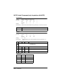
ESC c 0 n
[Name]
[Format]
[Range]
Select paper type(s) for printing
ASCII
ESC
c
0
Hex
1B
63
30
Decimal
27
99
48
1≤n≤4
n
n
n
Commands 5-13
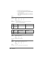
[Description]
Bit
Selects the type of paper for printing, using n as follows:
Off/On
Hex
Decimal
Function
Off
00
0
Paper roll disabled.
On
01
1
Paper roll enabled.
Off
00
0
Paper roll disabled.
On
02
2
Paper roll enabled.
Off
00
0
Slip paper disabled.
On
04
4
Slip paper enabled.
-
-
-
Undefined.
0
1
2
3-7
ESC c 1 n
[Name]
[Format]
Select paper type(s) for command settings
n
ASCII
ESC
c
1
n
Hex
1B
63
31
n
Decimal
27
99
49
[Range]
1≤n≤4
[Description] Selects paper type(s) for use with various command settings.
Bit
Off/On
Hex
Decimal
Function
Off
00
0
Paper roll disabled.
0
On
01
1
Paper roll enabled.
Off
00
0
Paper roll disabled.
On
02
2
Paper roll enabled.
Off
00
0
Slip paper disabled.
On
04
4
Slip paper enabled.
-
-
-
Undefined.
1
2
3-7
ESC c 3 n
[Name]
[Format]
Select paper sensor(s) to output paper end signals
n
ASCII
ESC
c
3
n
Hex
1B
63
33
n
Decimal
27
99
51
[Range]
0 ≤ n ≤ 255
[Description] Selects the paper sensor(s) to output paper end signals
• This command is available only with a parallel interface and is
ignored with a serial interface.
5-14 Commands
• Each bit of n is used as follows:
Bit
Off/On
Hex
Decimal
Function
Off
00
0
Paper roll near-end sensor disabled.
On
01
1
Paper roll near-end sensor enabled.
Off
00
0
Paper roll near-end sensor disabled.
On
02
2
Paper roll near-end sensor enabled.
Off
00
0
Paper roll end sensor disabled.
On
04
4
Paper roll end sensor enabled.
Off
00
0
Paper roll end sensor disabled.
On
08
8
Paper roll end sensor enabled.
Off
00
0
TOF sensor disabled.
0
1
2
3
4
On
10
16
TOF sensor enabled.
Off
00
0
BOF sensor disabled.
On
20
32
BOF sensor enabled.
-
-
-
Undefined.
5
6, 7
ESC c 4 n
[Name]
[Format]
Select paper sensor(s) to stop printing
n
ASCII
ESC
c
4
n
Hex
1B
63
34
n
Decimal
27
99
52
[Range]
0 ≤ n ≤ 255
[Description] Selects the paper sensor(s) used to stop printing when a paper-end is
detected, using n as follows:
Bit
Off/On
Hex
Decimal
Function
Off
00
0
Paper roll near-end sensor disabled.
0
On
01
1
Paper roll near-end sensor enabled.
Off
00
0
Paper roll near-end sensor disabled.
On
02
2
Paper roll near-end sensor enabled.
-
-
-
Undefined.
Off
00
0
TOF sensor disabled.
On
10
16
TOF sensor enabled.
1
2-3
4
Commands 5-15
Bit
Off/On
Hex
Decimal
Function
Off
00
0
BOF sensor disabled.
On
20
32
BOF sensor enabled.
-
-
-
Undefined.
5
6-7
ESC c 5 n
[Name]
[Format]
Enable/disable panel buttons
n
ASCII
ESC
c
5
n
Hex
1B
63
35
n
Decimal
27
99
53
[Range]
0 ≤ n ≤ 255
[Description] Enables or disables the panel buttons.
• When the LSB is 0, the panel buttons are enabled.
• When the LSB is 1, the panel buttons are disabled.
ESC d n
Print and feed n lines
n
ASCII
ESC
d
n
Hex
1B
64
n
Decimal
27
100
[Range]
0 ≤ n ≤ 255
[Description] Prints the data in the print buffer and feeds n lines.
[Name]
[Format]
ESC e n
Print and reverse feed n lines
n
ASCII
ESC
e
n
Hex
1B
65
n
Decimal
27
101
[Range]
0 ≤ n ≤ 255
[Description] Prints data in the print buffer and feeds n lines in the reverse direction.
• This command is available only when the slip paper is selected
as the print sheet.
[Name]
[Format]
ESC f t1 t2
[Name]
[Format]
Set cut sheet waiting time
t1 t2
ASCII
ESC
f
t1 t2
Hex
1B
66
t1 t2
Decimal
27
102
[Range]
0 ≤ t1 ≤ 15
0 ≤ t2 ≤ 64
[Description]
Sets the time that the printer waits for slip paper to be inserted and the
time from insertion of the slip to the start of printing.
5-16 Commands
• t1 sets the slip paper wait time to [t1 × 1] minutes.
• t2 sets the time from insertion of the slip paper to the start of
printing to [t2 × 0.1] seconds.
ESC p m t1 t2
[Name]
[Format]
Generate pulse
mt1 t2
ASCII
ESC
p
mt1 t2
Hex
1B
70
mt1 t2
Decimal
27
112
m = 0, 1, 48, 49
[Range]
0 ≤ t1 ≤ 255, 0≤ t2 ≤ 255
[Description] Outputs the pulse specified by t1 and t2 to connector pin m as follows:
m
Connector pin
0, 48
Drawer kick-out connector pin 2.
1, 49
Drawer kick-out connector pin 5.
ESC q
[Name]
[Format]
Paper release
ASCII
ESC
Hex
1B
Decimal
27
[Description] Releases the paper
q
71
113
ESC t n
[Name]
[Format]
Select character code table
n
ASCII
ESC
t
n
Hex
1B
74
n
Decimal
27
116
[Range]
0 ≤ n ≤ 5, n = 255
[Description] Selects a page n from the character code table.
n
Page
0
0 (PC437 [U.S.A., Standard Europe])
1
1 (Katakana)
2
2 (Pc850 [Multilingual])
3
3 (PC860 [Portuguese])
4
4 (PC863 [Canadian-French])
Commands 5-17
n
Page
5
5 (PC865 [Nordic])
255
Only when the character font B (7 × 9) is selected with the slip; otherwise,
they are all spaces.
ESC { n
[Name]
[Format]
Turns upside-down printing mode on/off
n
ASCII
ESC
{
n
Hex
1B
7B
n
Decimal
27
123
[Range]
0 ≤ n ≤ 255
[Description] Turns upside-down printing mode on or off.
• When the LSB is 0, upside-down printing mode is turned off.
• When the LSB is 1, upside-down printing mode is turned on.
GS ! n
[Name]
[Format]
Select character size
n
ASCII
GS
!
n
Hex
1D
21
n
Decimal
29
33
[Range]
0 ≤ n ≤ 255
(1 ≤ vertical number of times ≤ 8, 1 ≤ horizontal number of times ≤ 8)
[Description]
Selects the character height using bits 0 to 3 and selects the character
width using bits 4 to 7, as follows:
Bit
Off/On
Hex
Decimal
Function
0
1
Character height selection. See Table 2.
2
3
4
5
Character width selection. See Table 1.
6
7
5-18 Commands
Table 1
Character Width Selection
Table 2
Character Height Selection
Hex
Decimal
Hex
00
0
1 (normal)
00
0
1(normal)
10
16
2 (double-width)
01
1
2 (double-height)
20
32
3
02
2
3
30
48
4
03
3
4
40
64
5
04
4
5
50
80
6
05
5
6
60
96
7
06
6
7
70
112
8
07
7
8
Width
Decimal
Height
GS $ nL nH
[Name]
[Format]
Set absolute vertical print position in page mode
nL nH
ASCII
GS
$
nL nH
Hex
1D
24
nL nH
Decimal
29
36
[Range]
0 ≤ nL ≤ 255, 0 ≤ nH ≤ 255
[Description]
• Sets the absolute vertical print starting position for buffer
character data in page mode.
• This command sets the absolute print position to [(nL + nH ×
256) × (vertical or horizontal motion unit)] inches.
GS ✻ x y d1 ... d(x × y × 8)
[Name]
[Format]
Define downloaded bit-image
ASCII
GS
✻
Hex
1D
2A
Decimal
29
42
x
x
x
y
y
y
d1 ... d(x × y × 8)
d1 ... d(x × y × 8)
d1 ... d(x × y × 8)
[Range]
1 ≤ x ≤ 255
1 ≤ y ≤ 48 (for the paper roll)
x × y ≤ 1536 (for the paper roll)
1 ≤ y ≤ 255 (for slip paper)
x × y ≤ 404 (for slip paper)
0 ≤ d ≤ 255
[Description]
Defines a downloaded bit-image using the number of dots specified
by x and y
• The number of dots in the horizontal direction is x × 8 .
Commands 5-19
• The number of dots in the vertical direction is y × 8.
• If x × y is out of the specified range, this command is ignored.
• The d indicates bit-image data. Data (d) specifies a bit printed
to 1 and not printed to 0.
• After a downloaded bit-image is defined, it is available until
ESC @ or ESC & is executed; the printer is reset; or the power
is turned off.
GS / m
[Name]
[Format]
Print downloaded bit-image
m
ASCII
GS
/
m
Hex
1D
2F
m
Decimal
29
47
[Range]
0 ≤ m ≤ 3, 48 ≤ m ≤ 51
[Description]
Prints a downloaded bit-image using the mode specified by m.
m selects a mode from the table below:
<Paper roll>
m
Mode
Vertical Dot Density (DPI)
Horizontal Dot Density (DPI)
0, 48
1, 49
2, 50
3, 51
Normal
Double-width
Double-height
Quadruple
180
180
90
90
180
90
180
90
<Slip paper>
m
Mode
Adjacent Dot Printing
Maximum Number of
Horizontal Dots
0, 48
1, 49
Normal
Double-width
Not available
Available
800
400
GS :
[Name]
[Format]
Start/end macro definition
ASCII
GS
:
Hex
1D
3A
Decimal
29
58
[Description] Starts or ends macro definition.
GS B n
[Name]
[Format]
Turn white/black reverse printing mode on/off
n
ASCII
GS
B
n
Hex
1D
42
n
Decimal
29
66
[Range]
0 ≤ n ≤ 255
[Description] Turns on or off white/black reverse printing mode.
5-20 Commands
• When the LSB is 0, white/black reverse mode is turned off.
• When the LSB is 1, white/black reverse mode is turned on.
GS H n
[Name]
[Format]
Select printing position of HRI characters
n
ASCII
GS
H
n
Hex
1D
48
n
Decimal
29
72
[Range]
0 ≤ n ≤ 3, 48 ≤ n ≤ 51
[Description] Selects the printing position of HRI characters when printing a bar code.
n selects the printing position as follows:
n
Printing posiition
0, 48
Not printed.
1, 49
Above bar code.
2, 50
Below bar code.
3, 51
Both above and below the bar code.
• HRI indicates Human Readable Interpretation.
GS I n
[Name]
[Format]
Transmit printer ID
n
ASCII
GS
I
n
Hex
1D
49
n
Decimal
29
73
[Range]
1 ≤ n ≤ 3, 49 ≤ n ≤ 51
[Description] Transmits the printer ID specified by n as follows:
n
Printer ID
Specification
ID (hexidecimal)
1, 49
2, 50
Printer model ID
TM-H5000/H5000P
0FH
Type ID
See table below.
3, 51
ROM version ID
Depends on ROM version.
n=2, Type ID
Bit
Off/On
Hex
Decimal
Function
0
Off
00
0
Two-byte character code not supported.
1
On
02
2
Auto-cutter equipped.
Off
00
0
DIP switch 2-2 is set to off.
On
04
4
DIP switch 2-2 is set to on.
2
Commands 5-21
Bit
Off/On
Hex
Decimal
Function
Off
00
0
No MICR reader.
On
08
8
A MICR reader is installed.
4
Off
00
0
Not used. Fixed to Off.
5
-
-
-
Undefined.
6
-
-
-
Undefined.
7
Off
00
0
Not used. Fixed to Off.
3
GS L nL nH
[Name]
[Format]
Set left margin
nH
nL
ASCII
GS
L
nH
nL
Hex
1D
4C
nH
nL
Decimal
29
76
[Range]
0 ≤ nL ≤ 255
0 ≤ nH ≤ 255
[Description] Sets the left margin using nL and nH in standard mode.
• The left margin is set to [(nL + nH × 256) × horizontal motion
unit)] inches from the beginning of the line.
GS P x y
[Name]
[Format]
Set horizontal and vertical motion units
x
y
ASCII
GS
P
x
y
Hex
1D
50
x
y
Decimal
29
80
[Range]
0 ≤ x ≤ 255
0 ≤ y ≤ 255
[Description]
Sets the horizontal and vertical motion units to 1/x inch and 1/y
inches, respectively.
• When x and y are set to 0, the default setting of each value is
used.
➀ GS V m ➁ GS V m n
[Name]
[Format]
[Range]
5-22 Commands
Select cut mode and cut paper
GS
V
➀ASCII
Hex
1D
56
Decimal
29
86
GS
V
➁ASCII
Hex
1D
56
Decimal
29
86
➀ m = 1, 49
➁ m = 66, 0 ≤ n ≤ 255
m
m
m
m
m
m
n
n
n
[Description]
Selects a mode for cutting paper and executes paper cutting. The
value of m selects the mode as follows:
m
Print mode
1, 49
Partial cut (one point left uncut)
66
Feeds paper (cutting position + [n × (vertical motion unit)]), and cuts the
paper partially (one point left uncut)
GS W nL nH
[Name]
[Format]
[Range]
Set printing area width
ASCII
GS
W
Hex
1D
57
Decimal
29
87
0 ≤ nL≤ 255
0 ≤ nH ≤ 255
nL
nL
nL
nH
nH
nH
[Description] Sets the printing area width to the area specified by nL and nH in
standard mode .
• The printing area width is set to [(nL + nH × 256) × horizontal
motion unit)] inches from the left margin.
GS \ nL nH
[Name]
[Format]
Set relative vertical print position in page mode
nL nH
ASCII
GS
\
nL nH
Hex
1D
5C
nL nH
Decimal
29
92
[Range]
0 ≤ nL ≤ 255
0 ≤ nH ≤ 255
[Description]
Sets the relative vertical print starting position from the current
position in page mode.
• This command sets the distance from the current position to
[(nL + nH × 256) × vertical or horizontal motion unit] inches.
GS ^ r t m
[Name]
[Format]
Execute macro
rtm
ASCII
GS
^
rtm
Hex
1D
5E
rtm
Decimal
29
94
[Range]
0 ≤ r ≤ 255
0 ≤ t ≤ 255
m = 0, 1
[Description] Executes a macro.
• r specifies the number of times to execute the macro.
• t specifies the waiting time for executing the macro.
The waiting time is t × 100 msec for every macro execution.
Commands 5-23
• m specifies macro executing mode.
• When m = 0:
The macro executes r times continuously with interval specified by t.
• When m = 1:
After waiting for the period specified by t, the PAPER OUT and SLIP
LED indicators blink and the printer waits for the FEED, FORWARD
or REVERSE button to be pressed. After the button is pressed, the
printer executes the macro once. The printer repeats the operation r
times.
GS a n
[Name]
[Format]
Enable/Disable Automatic Status Back (ASB)
n
ASCII
GS
a
n
Hex
1D
61
n
Decimal
29
97
[Range]
0 ≤ n ≤ 255
[Description]
Enables or disables ASB and specifies the status items to include, using
n as follows:
Bit
Off/On
Hex
Decimal
Status for ASB
Off
00
0
Drawer kick-out connector pin 3 status disabled.
On
01
1
Drawer kick-out connector pin 3 status enabled.
Off
00
0
On-line/off-line status disabled.
On
02
2
On-line/off-line status enabled.
Off
00
0
Error status disabled.
On
04
4
Error status enabled.
Off
00
0
Paper roll sensor status disabled.
0
1
2
3
4
On
08
8
Paper roll sensor status enabled.
-
-
-
Undefined.
Off
00
0
Slip paper sensor status disabled.
On
20
32
Slip paper sensor status enabled.
-
-
-
Undefined.
5
6, 7
GS b n
[Name]
[Format]
Turns smoothing mode on/off
n
ASCII
GS
b
n
Hex
1D
62
n
Decimal
29
98
[Range]
0 ≤ n ≤ 255
[Description] Turns smoothing mode on or off.
5-24 Commands
• When the LSB is 0, smoothing mode is turned off.
• When the LSB is 1, smoothing mode is turned on.
GS f n
[Name]
[Format]
Select font for Human Readable Interpretation (HRI) characters
n
ASCII
GS
f
n
Hex
1D
66
n
Decimal
29
102
n = 0, 1, 48, 49
[Range]
[Description] Selects a font for the HRI characters used when printing a bar code.
n selects a font from the following table:
n
Font
0, 48
Font A (12 × 24)
1, 49
Font B (9 × 24)
• HRI indicates Human Readable Interpretation.
GS h n
[Name]
[Format]
Set bar code height
n
ASCII
GS
h
n
Hex
1D
68
n
Decimal
29
104
[Range]
1 ≤ n ≤ 255
[Description] Sets the height of the bar code.
n specifies the number of dots in the vertical direction.
➀ GS k m d1...dk NUL ➁ GS k m n d1...dn
[Name]
[Format]
Print bar code
m d1...dkNUL
➀ ASCII
GS
k
m d1...dk 00
Hex
1D
6B
m d1...dk 0
Decimal 29
107
m n d1...dn
➁ ASCII
GS
k
m n d1...dn
Hex
1D
6B
m n d1...dn
Decimal 29
107
➀ 0 ≤ m ≤ 6 (k and d depends on the bar code system used)
[Range]
➁ 65 ≤ m ≤ 73 (n and d depends on the bar code system used)
[Description] Selects a bar code system and prints the bar code.
Commands 5-25
m selects a bar code system as follows:
m
➀
➁
Bar Code System
Number of Characters
Remarks
0
UPC-A
11 ≤ k ≤ 12
48 ≤ d ≤ 57
1
UPC-E
11 ≤ k ≤ 12
48 ≤ d ≤ 57
2
JAN13 (EAN 13)
12 ≤ k ≤ 13
48 ≤ d ≤ 57
3
JAN 8 (EAN 8)
7≤k≤8
48 ≤ d ≤ 57
4
CODE39
1≤k
48 ≤ d ≤ 57, 65 ≤ d ≤ 90
d = 32, 36, 37, 43, 45, 46,
47
5
ITF
1 ≤ k (even number)
48 ≤ d ≤ 57
6
CODABAR
1≤k
48 ≤ d ≤ 57, 65 ≤ d ≤ 68
d = 36, 43, 45, 46, 47, 58
65
UPC-A
11 ≤ n ≤ 12
48 ≤ d ≤ 57
66
UPC-E
11 ≤ n ≤ 12
48 ≤ d ≤ 57
67
JAN13 (EAN 13)
12 ≤ n ≤ 13
48 ≤ d ≤ 57
68
JAN 8 (EAN 8)
7≤n≤8
48 ≤ d ≤ 57
69
CODE39
1 ≤ n ≤ 255
48 ≤ d ≤ 57, 65 ≤ d ≤ 90
d = 32, 36, 37, 43, 45, 46,
47
70
ITF
1 ≤ n ≤ 255 (even number)
48 ≤ d ≤ 57
71
DODABAR
1 ≤ n ≤ 255
48 ≤ d ≤ 57, 65 ≤ d ≤ 68
d = 36, 43, 45, 46, 47, 58
72
CODE93
1 ≤ n ≤ 255
0 ≤ d ≤ 127
73
DODE128
2 ≤ n ≤ 255
0 ≤ d ≤ 127
[Description for ➀]
• d indicates the character code to be printed and k indicates the
number of characters to be printed.
[Description for ➁]
• n indicates the number of bar code data, and the printer processes
n bytes from the next character data as bar code data.
• d indicates the character code to be printed.
GS r n
[Name]
5-26 Commands
Transmit status
n
ASCII
GS
r
n
Hex
1D
72
n
Decimal
29
114
[Range]
1 ≤ n ≤ 3, 49 ≤ n ≤ 51
[Description] Transmits the status specified by n as follows:
[Format]
n
Function
1, 49
Transmits paper sensor status
2, 50
Transmits drawer kick-out connector status
3, 51
Transmits slip status
GS w n
[Name]
[Format]
Set bar code width
n
ASCII
GS
w
n
Hex
1D
77
n
Decimal
29
119
[Range]
2≤n≤6
[Description] Set the horizontal size of the bar code.
n specifies the bar code width as follows::
Binary-level Bar Code
n
Module Width (mm)
for Multi-level Bar Code
Thin element width (mm)
Thick element width (mm)
2
0.282
0.282
0.706
3
0.423
0.423
1.129
4
0.564
0.564
1.411
5
0.706
0.706
1.834
6
0.847
0.847
2.258
• Multi-level bar codes are as follows:
UPC-A, UPC-E, JAN13 (EAN 13), JAN 8 (EAN 8), CODE93,
CODE128
• Binary-level bar codes are as follows:
CODE39, ITF, CODABAR
Commands 5-27
MICR Control Commands (only for printers with MICR)
DLE EOT BS n
[Name]
[Format]
Real-time MICR status transmission
n
ASCII
DLE
EOT
BS
n
Hex
10
04
08
n
Decimal
16
4
8
n=1
[Range]
[Description] Transmits the selected MICR status specified by n in real time as follows:
n
Function
1
Transmit MICR status
FS a 0 n
[Name]
[Format]
Read check paper
ASCII
FS
a
0
Hex
1C
61
30
Decimal
28
97
48
[Range]
0 ≤ n ≤ 255
[Description]
Selects MICR function and reads MICR characters specified by n as
follows:
Bit
Off/On
Hex
Decimal
Function
0
Readable fonts.
See the table below.
1
2,3
-
-
-
Undefined
4
Off
00
0
Not used. Fixed to Off.
5,6
-
-
-
Undefined
7
Off
00
0
Not used. Fixed to Off.
Readable Fonts
Bit 1
Bit 0
Font
0
0
E13B
0
1
CMC7
1
0
Undefined
1
1
Undefined
5-28 Commands
FS a 1
[Name]
[Format]
Load check paper to print starting position
ASCII
FS
a
1
Hex
1C
61
31
Decimal
28
97
49
[Description] Loads check paper to the print starting position
FS a 2
[Name]
[Format]
Eject check paper
ASCII
FS
Hex
1C
Decimal
28
[Description] Ejects check paper
a
61
97
2
32
50
FS b
[Name]
[Format]
Request retransmission of check paper reading result
ASCII
FS
b
Hex
1C
62
Decimal
28
98
[Description] Retransmits the previous check paper (MICR character) reading results.
FS c
[Name]
[Format]
MICR mechanism cleaning
ASCII
FS
c
Hex
1C
63
Decimal
28
99
[Description] Cleans the MICR mechanism.
Commands 5-29
5-30 Commands
Appendix A
Dip Switch and Paper Near End Settings
Although the factory settings are best for almost all uses, if you
have special requirements, you can change the DIP switch or paper
near end settings.
Setting the DIP Switches
DIP switch functions
Your printer has two sets of DIP switches. The functions of the
switches are shown in the following tables.
Serial interface specification
Set 1
SW
Function
ON
OFF
1-1
Data receive error
Ignored
Prints “?”
1-2
Receive buffer capacity
45 bytes
4K bytes
1-3
Handshaking
XON/XOFF
DTR/DSR
1-4
Data word length
7 bits
8 bits
1-5
Parity check
Enabled
Disabled
1-6
Parity selection
Even
Odd
1-7
Transmission speed (See the table below)
1-8
Dip Switch and Paper Near End Settings A-1
Transmission Speed
Transmission Speed (BPS)-bits per second
1-7
1-8
2400
ON
ON
4800
OFF
ON
9600
ON
OFF
19200
OFF
OFF
Set 2
SW
Function
ON
OFF
2-1
Handshaking (BUSY
condition)
Receive buffer full
Off line or
receive buffer full
2-2
Customer display
(DM-D) connection
Connected
Not connected
Selects print density
Refer to table below
2-3
2-4
2-5
Reserved: do not change settings
2-6
Fixed to OFF
2-7
I/F pin 6 reset signal
Enabled
Disabled
2-8
I/F pin 25 reset signal
Enabled
Disabled
Print Density Selection
Print Density
SW 2-3
SW 2-4
1 (Light)
ON
ON
2
OFF
OFF
3
ON
OFF
4 (Dark)
OFF
ON
A-2 Dip Switch and Paper Near End Settings
Notes:
• When pin 6 of the interface connector is used for the reset signal, the printer is
reset at MARK on the RS-232 level.
• When pin 25 of the interface connector is used for the reset signal, the printer
is reset at SPACE on the RS-232 level or at HIGH on the TTL level.
• Changes in DIP switch settings (excluding switches 2-7 and 2-8 interface reset
signals) are recognized only when the printer power is turned on or when the
printer is reset by using the interface. If the DIP switch setting is changed after
the printer power is turned on, the change does not take effect until the
printer is turned on again or is reset.
• If you turn on DIP switch 2-7 or 2-8 while the printer is turned on, the printer may
be reset, depending on the signal state. DIP switches should not be changed
while the printer power is on.
• If the print density is set to level 3 or 4, the printing will be at the low speed.
Dip Switch and Paper Near End Settings A-3
Parallel interface specification
Set 1
SW
Function
ON
OFF
1-1
Auto line feed
Always enabled
Always disabled
1-2
Receive buffer capacity
45 bytes
4K bytes
1-3 ~
1-8
Undefined
—
—
SW
Function
ON
OFF
2-1
Handshaking (BUSY
condition)
•Receive buffer full
•Reading data
•Off-line
•Receive buffer full
•Reading data
2-2
Reserved
(Do not change settings)
Fixed to Off
Selects print density
Refer to table below
2-5 ~
2-7
Reserved
(Do not change settings)
Fixed to Off
2-8
I/F pin 31 reset signal
(Do not change settings)
Fixed to On
Set 2
2-3
2-4
A-4 Dip Switch and Paper Near End Settings
Print Density Selection
Print Density
SW 2-3
SW 2-4
1 (Light)
ON
ON
2
OFF
OFF
3
ON
OFF
4 (Dark)
OFF
ON
Notes:
• When pin 6 of the interface connector is used for the reset signal, the printer is
reset at MARK on the RS-232 level.
• When pin 25 of the interface connector is used for the reset signal, the printer
is reset at SPACE on the RS-232 level or at HIGH on the TTL level.
• Changes in DIP switch settings (excluding switch 2-8 interface reset signal) are
recognized only when the printer power is turned on or when the printer is
reset by using the interface. If the DIP switch setting is changed after the
printer power is turned on, the change does not take effect until the printer is
turned on again or is reset.
• If you turn on DIP switch 2-8 while the printer is turned on, the printer may be
reset, depending on the signal state. DIP switches should not be changed
while the printer power is on.
• If the print density is set to level 3 or 4, the printing will be at the low speed.
Dip Switch and Paper Near End Settings A-5
Changing the DIP switch settings
If you need to change settings, follow the steps below to make your
changes:
CAUTION:
Turn off the printer while removing the DIP switch cover to
prevent an electric short, which can damage the printer.
1. Make sure the printer is turned off.
2. Remove the screw from the DIP switch cover. Then take off the
DIP switch cover, as shown in the illustration below.
DSW1 DSW2
3. Set the switches using a pointed tool, such as tweezers or a
small screwdriver.
4. Replace the DIP switch cover. Then secure it with the screw.
The new settings take effect when you turn on the printer.
A-6 Dip Switch and Paper Near End Settings
Adjusting the Paper Near End Sensor
The paper near end sensor detects when paper is almost gone by
measuring the diameter of the paper roll. The sensor has two
settings.
Because of variations in paper roll cores, it is not possible for the
sensor to measure exactly the length of paper left on the roll when
the sensor is triggered. Of the two settings, the factory setting
(lower) leaves the least amount of paper on the roll when the
sensor is triggered. If you want more paper left, change the setting
as described below.
Note:
The factory setting is based on a paper roll core with an outside
diameter of 18mm and an inside diameter of 12mm. If you use a
paper roll with a core with an outside diameter of more than 18mm,
it is better to change to the upper setting, as described below.
1. Open the paper roll cover, and remove the paper roll.
2. Loosen the adjusting screw and move the tab up to the upper
setting.
Tab
Screw
R
WE
PO OR
R
ER ER
P
PA T
OU
ED
FE
3. Tighten the adjusting screw, and check to be sure that the
detecting lever moves freely.
Dip Switch and Paper Near End Settings A-7
4. Replace the paper roll.
A-8 Dip Switch and Paper Near End Settings
Appendix B
EPSON Sales Subsidiaries
EPSON AMERICA INC./OEM DIV.
20770 Madrona Ave.
Torrance, CA 90559-2842 U.S.A.
Tel : 1-310-787-6300
Fax : 1-310-782-5350
EPSON EUROPE B.V.
Prof. J.H. Bavincklaan 5
1183 AT Amstelveen The Netherlands
Tel : 31-(0)20-5475-251
Fax : 31-(0)20-6454-315
EPSON Deutschland GmbH
Zülpicher Strasse 6, 40549
Düsseldorf 11, Germany
Tel : 49-(0)211-5603218
Fax : 49-(0)211-8584768
EPSON U.K. LIMITED
Campus 100 Maylands Ave.
Hemel Hempstead Herts. HP2 7TJ
United Kingdom
Tel : 44-1(0)442-61144
Fax : 44-1-(0)442-227-244
EPSON FRANCE S.A.
68 Bis Rue Marjolin B.P. 320 92305
Levallois Perret Cedex, France
Tel : 33-(0)1-40-87-38-62
Fax : 33-(0)1-47-37-15-10
EPSON IBERICA, S.A.
Avda. de Roma, 18-26
08290 Cerdanyola del Vallès (Barcelona), Spain
Tel : 34-(9)3-582-2500
Fax : 34-(9)(3-582-1555
EPSON ITALIA S.P.A.
V.le F IIi Casiraghi, 427
20099 Sesto Si Giovanni (Milan), Italy
Tel : (39)226-2331
Fax (39)2244-0750
EPSON SINGAPORE PTE. LTD.
No. 1 Raffles Place #26-00 OUB
Centre Singapore, 0104
Tel : 5-530477
Fax : 5-5338119
EPSON Sales Subsidiaries B-1
EPSON HONG KONG LIMITED
25/F., Harbor Centre, 25, Harbor Road,
Wanchai, Hong Kong
Tel : 852-2-585-4663
Fax : 852-2-827-4346
EPSON TAIWAN TECHNOLOGY
& TRADING LTD.
10f, No. 287, Nanking E. Road, Sec. 3
Taipei, Taiwan R.O.C.
Tel : 886-(0)2-717-7360
Fax : 886-(0)2-718-9366
SEIKO EPSON CORP.
KOREA OFFICE
10F, KIL 63 Building 60,
Yoido Dong, Youngedungpo-Ku,
Seoul, Korea
Tel : 82-(0)2-784-6027
Fax : 82-(0)2-769-1049
EPSON AUSTRALIA PTY. LTD.
70 Gibbes Street, Chatswood NSW 2067
Australia
Tel : 61-(0)2-415-9000
Fax : 61-(0)2-417-0077
EPSON HANBAI CO., LTD.
TOKYO OFFICE:
OSAKA OFFICE:
B-2 EPSON Sales Subsidiaries
3F Building Kawaguchi
Fuda Chofu-Shi Tokyo 182 Japan
Tel : 0424-99-7829
Fax : 0424-99-7834
13F Shin-Osaka Daiichi-Seimei Bldg.
5-24 3-Chome Miyahara Yodogawa-ku
Osaka 532 Japan
Tel : 06-350-4964
Fax : 06-350-4968