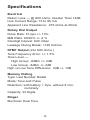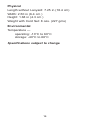
1
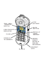
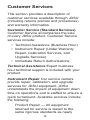
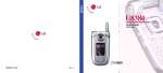
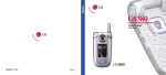
Lil' Buttief Telephone Test Set
User's Guide
www.jdsu.com/know
TALK - BELL
- MONITOR
SWITCH
LOW
BATTERY
Talk
Test
www
Bell
LINE POLARITY
INDICATOR
-U
.Test-m In
Um. c.
com
Lil'
TONE
Flas
M
Polar
Mad
e in
USA
But
h St
or
PULS
E
Mut
tie
e La
st/P
Store
e
TM
Mem
Lst/P
Mem
1
2ABC
4 GHI
STORE #
TO MEMORY
ity
REV
Flsh
FLASH
MUTE
BUTTON
NOR
Line
Mon
7 PRS
*
/T
5 JKL
8 TUV
3 DEF
RECALL #
FROM
MEMORY
6 MNO
9 WXY
0 QZ
#
RJ JACK
REDIAL/
INSERT
PAUSE IN
DIALING
SEQUENCE
HEADSET
JACK
Caution
Please follow correct safety practices when
operating this unit. Do not connect this unit
to 110 volt or 220 volt AC electric power
lines. In bell mode, any signal applied to
the unit with more than 250V peak-topeak voltage or resulting in more than 7
mA of rms current through ring or tip for
a prolonged period of time could damage
the unit. Correct operation is entirely the
responsibility of the user. Should the Lil'
Buttie, intentionally or by accident, be
connected to electric power, all warranties
are immediately null and void.
General Description
Lil' ButtieTM is a self-contained, selfpowered, portable telephone test set for
use by installers, repair technicians, and
other authorized personnel for temporary
communications and to test the operational
service and installation of telephone/data
lines.
A compact size and comfortable ergonomic
shape makes it small enough to carry in your
pocket or to wear on your belt, while still
retaining the normal earpiece-to-microphone
dimensional spacing for comfortable use
while resting on the shoulder.
Included headset jack and ear-mounted
headset allows for hands-free operation.
Headset is compact enough to fit in a shirt
pocket and can be worn on either ear. Its
unobtrusive design makes it easy to use
while wearing a hard hat or inclement
weather clothing.
The body is made of high impact resistant
abs to withstand the rough handling
and shocks that craft tools are normally
subjected to in their everyday use.
A belt loop provides a convenient and
secure location for the attachment of the
unit to various locations. An optional belt clip
attachment is also provided.
The modular jack cord set with strain relief
feature allows for easy field replacement or
direct connection to modular wall jack with a
standard phone cord set.
Features
•
Tone and Pulse Dialing
•
Microphone Mute Feature
•
Last Number Redial - 32 Digits
•
Continuous Line Polarity Indication (talk
or monitor)
•
Electronic Ringer
•
Amplified Line Monitor for volume levels
comparable to “off hook” operation.
•
Modular cord set attachment
•
Low Battery Indicator
•
Headset Jack for hands-free operation
•
Battery-Powered Monitor Mode with
auto power off on dead lines or when
disconnected.
Function Switches, Buttons,
and LEDs
Talk-Bell-Monitor Switch - This threeposition slide switch is located on the side of
the unit below the receiver. It is used to select
the mode of operation.
Talk - This position creates an off-hook
condition. In this mode, the unit can be used
for signaling, conversation and testing, just
like an ordinary telephone.
Bell - This position connects the internal
electronic ringer for receipt of incoming ring
signals. This on-hook mode also isolates both
the testing and speech circuits from the line.
Monitor - The battery is off in this mode. This
position connects the test set through a high
impedance coupling. This on-hook connection
allows for telephone line monitoring without
disturbing conversations, network signaling,
or data transmissions. In this mode, the unit’s
speech, ring and test circuits are isolated from
the line.
Tone-Pulse Switch - This two-position slide
switch is used to select the dialing mode. The
tone position selects dtmf signaling. The pulse
position selects rotary style pulse dialing.
Mute - This button is located on the opposite
side of the Talk-Bell-Monitor switch. Press
and hold to shut the unit's transmitter off.
This feature may also be used to improve
communications in noisy locations where it is
difficult for the user to hear a person on the
other end of the line.
Flash - When pressed, causes a 0.6 second
interruption of the loop current (hook flash).
Usually used for register recall, to put a call
on hold, to activate a second line, or where
some special function needs to be activated.
*/T When pressed in pulse mode, switches
from pulse to tone dialing mode.
Store - Press Store, enter the number you
wish to store, press Store and the location on
the numeric keypad (0-9) where you wish to
store the number. Ten 17 digit numbers can
be stored.
Last/P - When pressed first, the last number
dialed will be redialed from the unit’s internal
memory. When pressed after another digit,
a pause of approximately 3.6 seconds is
inserted in the dialing sequence for pbx or
Centrex switch dialing or other systems that
require an intermediate access digit in order
to access a line.
Mem - To retrieve a stored number, press
Mem and the numeric key (0-9) you stored
the number to and the number will be
automatically dialed.
Line Polarity Indicators
NORM - A green led indicates correct
polarity
REV - A red
polarity
led
indicates reversed line
Battery Low (BATT LOW) - When operated
in the Monitor or Talk mode, the led will light
up if low battery voltage is detected.
Operation
NOTE: Always position the Talk-BellMonitor Switch in the Monitor position before
connecting to a subscriber line to avoid
possibly compromising any transmission in
progress.
Connecting to a Line
Monitor
. Select the Monitor mode.
.
Connect the red cord set lead to Ring () and black cord set lead to Tip (+).
.
orm or rev polarity led will come on if
n
the line is powered. Listen for voices,
ambient noise, or buzzing sounds,
indicating digital data.
ote: If detected, the Low Batt led will
N
indicate a low operating voltage in this
mode.
Dialing
. Select the Monitor mode.
.
Connect the red cord set lead to Ring () and black cord set lead to Tip (+).
.
Confirm that the line is not in use.
.
Position the Tone-Pulse Switch to either
tone or pulse dialing.
.
Select the Talk mode and confirm that
dial tone is present.
6.
Proceed with dialing, line testing, etc.
Mixed-Mode Dialing
In certain situations, it may be necessary
to set up a call using both Pulse and Tone
dialing. In this situation, a number can be
entered in the Pulse mode then by pressing
the */T button, the unit will switch to Tone
mode so that tones can be sent to devices
such as answering machines, etc. that are
activated by specific tone codes.
Last Number Redial
The last number dialed can automatically be
redialed in either the Tone or Pulse modes.
To redial the last number, switch from Talk to
Monitor then back to Talk mode. Once you
have confirmed a dial tone press the Last/P
button on the keypad.
Ringer
. Select the Bell mode.
.
Connect the red cord set lead to Ring () and black cord set lead to Tip (+).
.
he unit will now "ring" when ringing
T
voltage is detected on the line.
.
To answer the call, switch the unit to
talk.
.
To disable the ringer, switch the unit to
monitor mode.
Polarity Check
The Lil' Buttie indicates Polarity continuously
in Monitor and Talk modes as long as the
line is powered.
.
To test, select the
.
onnect the black cord set lead to Ring
C
(+) and red cord set lead to Tip (-).
.
he red led will light up if the leads are
T
reversed and the green led will light up if
the polarity is correct.
monitor
or
talk
mode.
Line Cord Connections
The Lil' Buttie is designed with a standard
6-position modular jack for quick connection
to various cord sets. The jack is located at
the base of the unit below the microphone.
To replace the cord set, simply remove the
strain relief attachment screw and unplug
the cord set. Insert the new cord set and
replace the terminal and screw.
10
Models, Options & Accessories
Ordering
number
Description
LB100
Lil’ Buttie telephone test set
with piercing pin clips
LB110
Lil’ Buttie telephone test set
with angled bed-of-nails clips
LB110-BT
Lil’ Buttie telephone test set
with angled bed-of-nails clips
and protective rubber boot
LB110UK/AUS
Lil’ Buttie telephone test set
with angled bed-of-nails clips
(non-N. America 100ms hook
flash, 37/63 make/break ratio)
and protective rubber boot
LB115
Lil’ Buttie telephone test set
with angled bed-of-nails clips
and rugged hook-style belt clip
LB10B
RJ11 to alligator - 48” cord with
strain relief
LB25
LB30B
RJ11 to piercing pin - 48” with
strain relief
RJ11 to angled bed-of-nails
clips - 48” with strain relief
11
Headset
The included headset can be utilized when
a hands-free operation is preferred. Plug
the headset into the receptacle located at
the base of the unit next to the modular
plug receptacle. The headset can be used
for either ear by rotating the microphone
position 90 degrees.
NOTE: When the headset is plugged in, the
internal handset is disconnected.
Belt Clip Attachment
To install the Belt Clip Attachment, remove
the strain relief attahment screw and position
the Belt Clip as shown. Attach the clip using
the provided 3/8" flat head screw. Take
care not to over torque the screw to cause
damage to the body.
Belt clip
Strain Relief
Grommet
12
Optional Accessories
For a complete description of optional Field
Kits and accessories, visit out web site www.
jdsu.com/know.
13
Battery Installation
Battery not included. Should the Batt Low
led indicate low battery, the battery should
be replaced as shown below.
.
Using a #1 Phillips screwdriver, unscrew
and remove the battery cover on the
back of the Lil' Buttie.
.
Connect a 9V Alkaline battery to the
battery snaps.
.
Slide the battery into the cavity.
.
Close the battery cover and replace the
screw. Do not overtighten. When the
battery is low, the round indicator light
above the battery icon will be on and
the battery should be replaced as soon
as possible.
14
Specifications
Electrical
Return Loss — @ 600 ohms: Greater Than 14dB
Line Current Range: 15 to 85 mA
Apparent Line Resistance: 275 ohms at 20mA
Rotary Dial Output
Pulse Rate: 10 pps +/- 10%
M/B Ratio: 60/40% +/- 2 %
Interdigit Interval: 820 mSec
Leakage During Break: >120 Kohms
DTMF Output (into 600 ohms )
Tone Frequency Error: +/- 1.5%
Tone Level —
High Group: -6dBm +/- 2dB
Low Group: -8dBm +/- 2dB
High vs Low Tone Difference: 2dB +/- 1dB
Memory Dialing
Type: Last Number Redial
Mode: Tone and Pulse
Retention: with battery > 2yrs, without 8 min.
nominally
Capacity: 32 Digits
Ringer
Electronic Dual Tone
15
Physical
Length without Lanyard: 7.25 in (18.4 cm)
Width: 2.50 in (6.4 cm )
Height: 1.68 in (4.3 cm )
Weight with Cord Set: 8 ozs. (227 gms)
Environmental
Temperature —
operating: -10°C to 60°C
storage: -40°C to 66°C
Specifications subject to change
16
Maintenance
The test set may be cleaned with a damp
cloth. If heavy accumulations of dirt are
present, a small amount of liquid soap may
be applied to the cloth to assist in cleaning.
Do not use solvents, scouring powders, or
other abrasive cleaners as they may scratch
the unit and/or cause malfunctions.
Cord sets should be periodically checked for
shorts, continuity, or obvious signs of wear,
such as fraying or loose/damaged test clips.
17
Customer Services
This section provides a description of
customer services available through JDSU
(including returns policies and procedures)
and warranty information.
Customer Service (Standard Services)
Customer Service accompanies the sale
of every JDSU product. Customer Service
services include:
• Technical Assistance (Business Hour)
• Instrument Repair (Under Warranty
Repair, Calibration Services, and
Upgrade Services)
• Immediate Return Authorizations
Technical Assistance Expert business
hour technical support is included with your
product.
Instrument Repair Our service centers
provide repair, calibration, and upgrade
services for JDSU equipment. JDSU
understands the impact of equipment down
time on operations and is staffed to ensure a
quick turnaround. Available services include
the following:
Product Repair — All equipment
returned for service is tested to the
same rigorous standards as newly
18
manufactured equipment. This
ensures products meet all published
specifications, including any applicable
product updates.
Calibration — JDSU’s calibration
methods are ISO approved and based
on national standards.
Factory Upgrades — Any unit returned
for a hardware feature enhancement will
also receive applicable product updates
and will be thoroughly tested, ensuring
peak performance of the complete
feature set.
Equipment Return Instructions Please
contact your regional Technical Assistance
Center to get a Return or Reference
Authorization to accompany your equipment.
For each piece of equipment returned for
repair, attach a tag that includes the following
information:
•
•
•
•
Owner’s name, address, and
telephone number.
The serial number (if applicable),
product type, and model.
Warranty status. (If you are unsure
of the warranty status of your
instrument, contact Technical
Assistance.)
A detailed description of the
19
problem or service requested.
The name and telephone number
of the person to contact regarding
questions about the repair.
•
The return authorization (RA) number
(US customers), or reference number
(European Customers).
If possible, return the equipment using the
original shipping container and material. If
the original container is not available, the
unit should be carefully packed so that it will
not be damaged in transit; when needed,
appropriate packing materials can be obtained
by contacting JDSU Technical Assistance.
JDSU is not liable for any damage that may
occur during shipping. The customer should
clearly mark the JDSU-issued RA or reference
number on the outside of the package and
ship it prepaid and insured to JDSU.
•
Warranty Information
JDSU guarantees that its products will
be free of all defects in material and
workmanship. This warranty extends for the
period of 12 months for test instruments
and 3 months for cables from date of
manufacture or purchase (proof of purchase
required).
All product deemed defective under this
warranty will be repaired or replaced at
JDSU’s discretion. No further warranties
either implied or expressed will apply, nor
will responsibility for operation of this device
be assumed by JDSU.
WEEE Directive Compliance
JDSU has established processes in
compliance with the Waste Electrical and
Electronic Equipment (WEEE) Directive,
2 002 /96/EC. This product should not be
disposed of as unsorted municipal waste
and should be collected separately and
disposed of according to your national
regulations. In the European Union, all
equipment purchased from JDSU after
005 -08 -13 can be returned for disposal
at the end of its useful life. JDSU will
ensure that all waste equipment returned
is reused, recycled, or disposed of in an
environmentally friendly manner, and in
compliance with all applicable national
and international waste legislation. It is
the responsibility of the equipment owner
to return the equipment to JDSU for
appropriate disposal. If the equipment
was imported by a reseller whose name
or logo is marked on the equipment, then
the owner should return the equipment
directly to the reseller. Instructions for
returning waste equipment to JDSU can
be found in the Environmental section of
JDSU’s web site at www.jdsu.com. If you
have questions concerning disposal of your
equipment, contact JDSU’s WEEE Program
Management team at WEEE.EMEA@jdsu.
com.
Notes:
www.jdsu.com/know
Document Information
Doc. # TU9822
Revision 501, 06-08
English