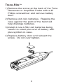
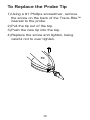
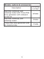
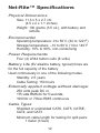
1
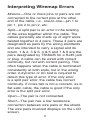
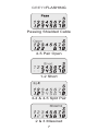
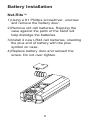
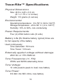
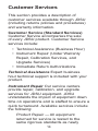
Net-Ritef Continuity and Wiremap Tester
Trace-Ritef Tone Generator and Amplified
Tone Tracer
User's Guide
www.jdsu.com/know
Voltage Probe
Tracer/Power
Button
Volume
Up/Down
Indicator
LED
Power/Tone
Type Switch
RJ11
RJ11
LCD
Screen
Remote
RJ11
Warning!
Do not attach to AC power, this may
damage the Net-Rite™ and the Trace-Rite™
generator and could cause a safety hazard
for the user.
Caution!
Improperly crimped, damaged or un-crimped
plugs can damage the jack on the NetRite™ and Trace-Rite™. Inspect plugs
for proper termination and crimping before
inserting into the tester. Contacts should
always be recessed into the plastic grooves
of the plug.
Features
Net-Rite™ Features
• Auto-on when sensing the remote or a
short
• Auto-off when the remote is
disconnected to conserve battery life
• Ergonomic shape, with soft edges
• When not in use, the remote stores in
the bottom of the main unit
Trace-Rite™ Features
• Self-powered Amplified Probe on the
Tone Tracer turns on when tone sensor
button is depressed and off when the
button is released
• Compact Tone Generator turns off
automatically when stored in the bottom
of the Tone Tracer to conserve battery
life
• Ergonomic shape with soft edges
• Two selectable tone styles with LED
indicator
• Changeable Round Tip Probe
• Adjustable Volume control
Instructions for Use
To Wiremap a Cable
1) Using the RJ45 jacks, connect Net-Rite™
main unit and remote to the cable you
want to test.
) An icon and the wiremap are always
displayed. Net-Rite™ reports:
a) PASS when the cable pins are
properly connected per T568A/B
and there are no other faults, or
b) an error icon when it does not
pass. Pins with errors flash an error
message: Miswire, Split, Open, Short,
or Reverse.
To Trace a Tone
1) Using the RJ12 jack on the remote,
connect the Trace-Rite™ Tone Generator
to the cable to be traced.
) Slide the Tone Generator switch up to
select one of the two tones (stutter tone
or fast stutter tone). The green LED lights
and flashes intermittently to indicate the
tone generator is powered on and which
tone speed has been selected.
) Press and hold the black button on the
Amplified Probe to turn on the probe.
4) Adjust volume control on the side of the
Trace-Rite™ to a comfortable level. If the
signal is very loud when near the cable,
adjust the volume to avoid overloading the
Trace-Rite™. When overloaded, small
increases or decreases in the signal at the
tip cannot be heard.
5) Hold the tip of the Trace-Rite™ near the
cable to be identified. The signal will be
loudest on the wire or cable attached to
the generator. Separating the wires or
cables may help in isolating the correct
cable.
Interpreting Wiremap Errors
Miswire—One or more pins or pairs are not
connected to the correct pins at the other
end of the cable, i.e., one-to-one—pin 1 to
pin 1, pin 2 to pin 2, etc.
Split—A split pair is an error in the twisting
of the wires together within the cable. The
cables generally are made up of eight wires
twisted together in 4 pairs. These 4 pairs are
designated as pairs by the wiring standards
and are intended to carry a signal and its
return. 1 & 2, 3 & 6, 4 & 5 and 7 & 8 are the
pairs designated by T568A/B for a RJ45 jack
or plug. A cable can be wired with correct
continuity, but not with correct pairing. This
often happens when the cable is terminated
consistently at both ends, but in the wrong
order. A dynamic or AC test is required to
detect this type of error. If the only error
is a split pair error, the cable has correct
continuity. If cross talk is not a concern, as in
flat satin cable, the cable is good if the only
error is the split pair error.
Open—The pair is not connected.
Short—The pair has a low resistance
connection between wire pairs or the shield.
The wire pairs involved displays on the LCD
screen.
Reverse—A reverse (Rev) pair is a special
case of a Miswire, and both icons will be
flashing. The wires are connected to the
correct pair of pins, but the two leads are
reversed.
Voltage—When voltage is detected on
any of the pins, lightning bolt icons flash.
Disconnect from the cable as soon as
possible.
GREY=FLASHING
Passing Shielded Cable
4-5 Pair Open
1-2 Short
3-4 & 4-5 Split Pair
2 & 3 Miswired
Battery Installation
Net-Rite™
1) Using a #1 Phillips screwdriver, unscrew
and remove the battery door.
) Remove old cell batteries. Rapping the
case against the palm of the hand will
help dislodge the batteries.
) Install 4 new LR44 cell batteries, orienting
the plus end of battery with the plus
symbol on case.
4) Replace battery door and reinsert the
screw. Do not over tighten.
Trace-Rite™
1) Remove the screw at the back of the Tone
Generator or Amplified Probe with a #1
Philips screwdriver and remove battery
door.
) Remove old coin batteries. Rapping the
case against the palm of the hand will
help dislodge batteries.
) Install 4 new LR44 cell batteries being
careful to orient plus end of battery with
plus symbol on case.
4) Replace battery door and reinsert the
screw. Do not over tighten.
To Replace the Probe Tip
1) Using a #1 Phillips screwdriver, remove
the screw on the back of the Trace-Rite™
nearest to the probe.
) Pull the tip out of the top.
) Push the new tip into the top.
4) Replace the screw and tighten, being
careful not to over tighten.
10
Models, options & accessories
Description
Ordering
number
Net-Rite continuity and
wiremap tester and Trace-Rite
tone generator with onboard
probe kit
KP260
Net-Rite continuity and
wiremap tester
TP250
Trace-Rite tone generator with
on-board probe
TT250
11
Net-Rite™ Specifications
Physical Dimensions
Size: 11.3 x 5 x 2.7 cm
(4.5 x 2 x 1.1 inches)
Weight: 100 grams (3.5 oz.), with battery and
remote
Environmental
Operating temperature: 0 to 50˚C (32 to 122˚F)
Storage temperature: –10 to 60˚C (14 to 140˚F
Humidity: 10% to 90%, non-condensing
Power Requirements
Four (4) LR44 button cells (6 volts)
Battery Life (6V alkaline battery, typical) times are
for the full capacity of the battery
Used continuously in one of the following modes
Standby: 2.5 years
Cable Testing: 150 hours
Externally applied voltage without damage:
250 volts peak DC or
175 volts RMS AC for 5 seconds,
100Vdc or 70Vac RMS continuous
Cable Types
Shielded or unshielded CAT6, CAT5, CAT5E,
CAT4, and CAT3
Minimum cable length for testing for split pairs:
1 meter (3 feet)
12
Trace-Rite™ Specifications
Physical Dimensions
Size: 20.6 x 4.45 x 3.0 cm
(8.1 x 1.75 x 1.2 inches)
Weight: 113 grams (4 ounces)
Environmental
Operating temperature: 0 to 50o C (32 to 122o F)
Storage temperature: -20 to 60o C (-4 to 140o F)
Humidity: 10% to 90%, non-condensing
Power Requirements
Four (4) LR44 button cells (6 volts)
Battery Life (6V Alkaline battery, typical) times are
for full capacity of the battery
Used continuously:
Tone Generator: 50 hours
Tone Tracer: 10 hours
Externally applied voltage without damage
250V DC or 175V RMS AC
Tone Frequencies (+/- 5%):
970Hz and 825Hz alternating tones
Tone Voltage:
12 volts peak-to-peak no load, new battery
Tone Power:
8.9 dbm into 600 ohms, new battery
13
Customer Services
This section provides a description of
customer services available through JDSU
(including returns policies and procedures)
and warranty information.
Customer Service (Standard Services)
Customer Service accompanies the sale
of every JDSU product. Customer Service
services include:
• Technical Assistance (Business Hour)
• Instrument Repair (Under Warranty
Repair, Calibration Services, and
Upgrade Services)
• Immediate Return Authorizations
Technical Assistance Expert business
hour technical support is included with your
product.
Instrument Repair Our service centers
provide repair, calibration, and upgrade
services for JDSU equipment. JDSU
understands the impact of equipment down
time on operations and is staffed to ensure a
quick turnaround. Available services include
the following:
Product Repair — All equipment
returned for service is tested to the
same rigorous standards as newly
14
manufactured equipment. This
ensures products meet all published
specifications, including any applicable
product updates.
Calibration — JDSU’s calibration
methods are ISO approved and based
on national standards.
Factory Upgrades — Any unit returned
for a hardware feature enhancement will
also receive applicable product updates
and will be thoroughly tested, ensuring
peak performance of the complete
feature set.
Equipment Return Instructions Please
contact your regional Technical Assistance
Center to get a Return or Reference
Authorization to accompany your equipment.
For each piece of equipment returned for
repair, attach a tag that includes the following
information:
•
•
•
Owner’s name, address, and
telephone number.
The serial number (if applicable),
product type, and model.
Warranty status. (If you are unsure
of the warranty status of your
instrument, contact Technical
Assistance.)
15
•
A detailed description of the
problem or service requested.
•
The name and telephone number
of the person to contact regarding
questions about the repair.
•
The return authorization (RA)
number (US customers), or
reference number (European
Customers).
If possible, return the equipment using the
original shipping container and material.
If the original container is not available,
the unit should be carefully packed so
that it will not be damaged in transit; when
needed, appropriate packing materials can
be obtained by contacting JDSU Technical
Assistance. JDSU is not liable for any
damage that may occur during shipping. The
customer should clearly mark the JDSUissued RA or reference number on the
outside of the package and ship it prepaid
and insured to JDSU.
16
Warranty Information
JDSU guarantees that its products will
be free of all defects in material and
workmanship. This warranty extends for the
period of 12 months for test instruments
and 3 months for cables from date of
manufacture or purchase (proof of purchase
required).
All product deemed defective under this
warranty will be repaired or replaced at
JDSU’s discretion. No further warranties
either implied or expressed will apply, nor
will responsibility for operation of this device
be assumed by JDSU.
WEEE Directive Compliance
JDSU has established processes in
compliance with the Waste Electrical and
Electronic Equipment (WEEE) Directive,
2 002 /96/EC. This product should not be
disposed of as unsorted municipal waste
and should be collected separately and
disposed of according to your national
regulations. In the European Union, all
equipment purchased from JDSU after
005 -08 -13 can be returned for disposal
at the end of its useful life. JDSU will
ensure that all waste equipment returned
17
is reused, recycled, or disposed of in an
environmentally friendly manner, and in
compliance with all applicable national
and international waste legislation. It is
the responsibility of the equipment owner
to return the equipment to JDSU for
appropriate disposal. If the equipment
was imported by a reseller whose name
or logo is marked on the equipment, then
the owner should return the equipment
directly to the reseller. Instructions for
returning waste equipment to JDSU can
be found in the Environmental section of
JDSU’s web site at www.jdsu.com. If you
have questions concerning disposal of your
equipment, contact JDSU’s WEEE Program
Management team at WEEE.EMEA@jdsu.
com.
18
www.jdsu.com/know
Document Information
Doc. # TU9891
Revision 500, 04-08
English