1
Command Line Interface
Version 10.2 – Supports the 9750, 9690SA, and
9650SE Models
PN: 45413-00, Rev. A
May 2010
CLI Guide
3ware® SATA+SAS
RAID Controller Card
Document Description
Document 45413-01, Rev. A. May 2010.
This document will remain the official reference source for all revisions and
releases of this product until rescinded by an update.
Disclaimer
It is the policy of LSI Corporation to improve products as new technology,
components, software, and firmware become available. LSI reserves the right
to make changes to any products herein at any time without notice. All
features, functions, and operations described herein may not be marketed by
LSI in all parts of the world. In some instances, photographs and figures are of
equipment prototypes. Therefore, before using this document, consult your
LSI representative for information that is applicable and current. LSI DOES
NOT ASSUME ANY RESPONSIBILITY OR LIABILITY FOR THE USE
OF ANY PRODUCTS DESCRIBED HEREIN EXCEPT AS EXPRESSLY
AGREED TO IN WRITING BY LSI.
LSI products are not intended for use in life-support appliances, devices, or
systems. Use of any LSI product in such applications without written consent
of the appropriate LSI officer is prohibited.
License Restriction
The purchase or use of an LSI Corporation product does not convey a license
under any patent, copyright, trademark, or other intellectual property right of
LSI or third parties.
Copyright Notice
© 2010 LSI Corporation. All rights reserved.
Trademark Acknowledgments
LSI™, the LSI logo design, 3ware®, 3DM®, 3DM2™, StorSwitch®, and
TwinStor®, StorSave™, and StreamFusion™ + are trademarks or registered
trademarks of LSI Corporation.
Apple®, the Apple logo, Mac OS®, and Macintosh® are trademarks of Apple
Computer Inc., registered in the United States and/or other countries.
Sun, Solaris and OpenSolaris are trademarks or registered trademarks of Sun
Microsystems, Inc. in the U.S. and other countries. All other brand and
product names may be trademarks of their respective companies.
Table of Contents
About this CLI Guide . . . . . . . . . . . . . . . . . . . . . . . . . . . . . . . . . . . . . . . . viii
Chapter 1.
Introduction to the 3ware Command Line Interface. . . . . . . . . . . . . . . . . .1
Features of the CLI . . . . . . . . . . . . . . . . . . . . . . . . . . . . . . . . . . . . . . . . . . . . . . . . . . . 1
Supported Operating Systems . . . . . . . . . . . . . . . . . . . . . . . . . . . . . . . . . . . . . . . . . . 2
Installing the 3ware CLI . . . . . . . . . . . . . . . . . . . . . . . . . . . . . . . . . . . . . . . . . . . . . . . 2
Installing the 3ware CLI on Windows . . . . . . . . . . . . . . . . . . . . . . . . . . . . . . . . . . . 2
Installing the 3ware CLI on Linux, FreeBSD, OpenSolaris, and VMWare . . . . . . . 3
Installing the 3ware CLI on Mac OS X . . . . . . . . . . . . . . . . . . . . . . . . . . . . . . . . . . 6
Working with 3ware CLI . . . . . . . . . . . . . . . . . . . . . . . . . . . . . . . . . . . . . . . . . . . . . . . 6
Using the command interface interactively . . . . . . . . . . . . . . . . . . . . . . . . . . . . . . . 7
Using a single command with output . . . . . . . . . . . . . . . . . . . . . . . . . . . . . . . . . . . 7
Using an input file to execute a script . . . . . . . . . . . . . . . . . . . . . . . . . . . . . . . . . . . 8
Outputting the CLI to a Text File . . . . . . . . . . . . . . . . . . . . . . . . . . . . . . . . . . . . . . . 9
Conventions . . . . . . . . . . . . . . . . . . . . . . . . . . . . . . . . . . . . . . . . . . . . . . . . . . . . . . 9
Understanding RAID Levels and Concepts . . . . . . . . . . . . . . . . . . . . . . . . . . . . . . . . 9
RAID Concepts . . . . . . . . . . . . . . . . . . . . . . . . . . . . . . . . . . . . . . . . . . . . . . . . . . . 10
Available RAID Configurations . . . . . . . . . . . . . . . . . . . . . . . . . . . . . . . . . . . . . . . 11
Determining Which RAID Level to Use . . . . . . . . . . . . . . . . . . . . . . . . . . . . . . . . . 16
Using Drive Capacity Efficiently . . . . . . . . . . . . . . . . . . . . . . . . . . . . . . . . . . . . . . 17
Chapter 2.
CLI Syntax Reference . . . . . . . . . . . . . . . . . . . . . . . . . . . . . . . . . . . . . . . . .19
Common Tasks Mapped to CLI Commands . . . . . . . . . . . . . . . . . . . . . . . . . . . . . . .
Terminology . . . . . . . . . . . . . . . . . . . . . . . . . . . . . . . . . . . . . . . . . . . . . . . . . . . . . . .
Syntax Overview . . . . . . . . . . . . . . . . . . . . . . . . . . . . . . . . . . . . . . . . . . . . . . . . . . .
Shell Object Commands . . . . . . . . . . . . . . . . . . . . . . . . . . . . . . . . . . . . . . . . . . . . . .
focus Object . . . . . . . . . . . . . . . . . . . . . . . . . . . . . . . . . . . . . . . . . . . . . . . . . . . . .
commit . . . . . . . . . . . . . . . . . . . . . . . . . . . . . . . . . . . . . . . . . . . . . . . . . . . . . . . . . .
flush . . . . . . . . . . . . . . . . . . . . . . . . . . . . . . . . . . . . . . . . . . . . . . . . . . . . . . . . . . . .
rescan . . . . . . . . . . . . . . . . . . . . . . . . . . . . . . . . . . . . . . . . . . . . . . . . . . . . . . . . . .
show . . . . . . . . . . . . . . . . . . . . . . . . . . . . . . . . . . . . . . . . . . . . . . . . . . . . . . . . . . .
show alarms [reverse] . . . . . . . . . . . . . . . . . . . . . . . . . . . . . . . . . . . . . . . . . . . . . .
show events [reverse] . . . . . . . . . . . . . . . . . . . . . . . . . . . . . . . . . . . . . . . . . . . . . .
show AENs [reverse] . . . . . . . . . . . . . . . . . . . . . . . . . . . . . . . . . . . . . . . . . . . . . . .
show diag . . . . . . . . . . . . . . . . . . . . . . . . . . . . . . . . . . . . . . . . . . . . . . . . . . . . . . .
show rebuild . . . . . . . . . . . . . . . . . . . . . . . . . . . . . . . . . . . . . . . . . . . . . . . . . . . . .
show selftest . . . . . . . . . . . . . . . . . . . . . . . . . . . . . . . . . . . . . . . . . . . . . . . . . . . . .
show ver . . . . . . . . . . . . . . . . . . . . . . . . . . . . . . . . . . . . . . . . . . . . . . . . . . . . . . . .
show verify . . . . . . . . . . . . . . . . . . . . . . . . . . . . . . . . . . . . . . . . . . . . . . . . . . . . . .
update fw=filename_with_path [force] . . . . . . . . . . . . . . . . . . . . . . . . . . . . . . . . .
Controller Object Commands . . . . . . . . . . . . . . . . . . . . . . . . . . . . . . . . . . . . . . . . . .
/cx show . . . . . . . . . . . . . . . . . . . . . . . . . . . . . . . . . . . . . . . . . . . . . . . . . . . . . . . .
/cx show attribute [attribute ...] . . . . . . . . . . . . . . . . . . . . . . . . . . . . . . . . . . . . . . .
/cx show achip . . . . . . . . . . . . . . . . . . . . . . . . . . . . . . . . . . . . . . . . . . . . . . . . .
/cx show allunitstatus . . . . . . . . . . . . . . . . . . . . . . . . . . . . . . . . . . . . . . . . . . . .
/cx show autocarve . . . . . . . . . . . . . . . . . . . . . . . . . . . . . . . . . . . . . . . . . . . . .
/cx show autorebuild . . . . . . . . . . . . . . . . . . . . . . . . . . . . . . . . . . . . . . . . . . . .
/cx show bios . . . . . . . . . . . . . . . . . . . . . . . . . . . . . . . . . . . . . . . . . . . . . . . . . .
www.lsi.com/channel/products
19
22
23
25
25
26
26
26
26
27
28
28
28
28
29
29
29
30
30
32
33
34
34
34
34
35
iii
/cx show carvesize . . . . . . . . . . . . . . . . . . . . . . . . . . . . . . . . . . . . . . . . . . . . .
/cx show ctlbus . . . . . . . . . . . . . . . . . . . . . . . . . . . . . . . . . . . . . . . . . . . . . . . .
/cx show driver . . . . . . . . . . . . . . . . . . . . . . . . . . . . . . . . . . . . . . . . . . . . . . . . .
/cx show dpmstat [type=inst|ra|ext] . . . . . . . . . . . . . . . . . . . . . . . . . . . . . . . . .
/cx show drivestatus . . . . . . . . . . . . . . . . . . . . . . . . . . . . . . . . . . . . . . . . . . . .
/cx show firmware . . . . . . . . . . . . . . . . . . . . . . . . . . . . . . . . . . . . . . . . . . . . . .
/cx show memory . . . . . . . . . . . . . . . . . . . . . . . . . . . . . . . . . . . . . . . . . . . . . . .
/cx show model . . . . . . . . . . . . . . . . . . . . . . . . . . . . . . . . . . . . . . . . . . . . . . . .
/cx show monitor . . . . . . . . . . . . . . . . . . . . . . . . . . . . . . . . . . . . . . . . . . . . . . .
/cx show numdrives . . . . . . . . . . . . . . . . . . . . . . . . . . . . . . . . . . . . . . . . . . . . .
/cx show numports . . . . . . . . . . . . . . . . . . . . . . . . . . . . . . . . . . . . . . . . . . . . . .
/cx show numunits . . . . . . . . . . . . . . . . . . . . . . . . . . . . . . . . . . . . . . . . . . . . . .
/cx show pcb . . . . . . . . . . . . . . . . . . . . . . . . . . . . . . . . . . . . . . . . . . . . . . . . . .
/cx show pchip . . . . . . . . . . . . . . . . . . . . . . . . . . . . . . . . . . . . . . . . . . . . . . . . .
/cx show serial . . . . . . . . . . . . . . . . . . . . . . . . . . . . . . . . . . . . . . . . . . . . . . . . .
/cx show spinup . . . . . . . . . . . . . . . . . . . . . . . . . . . . . . . . . . . . . . . . . . . . . . . .
/cx show stagger . . . . . . . . . . . . . . . . . . . . . . . . . . . . . . . . . . . . . . . . . . . . . . .
/cx show unitstatus . . . . . . . . . . . . . . . . . . . . . . . . . . . . . . . . . . . . . . . . . . . . .
/cx show all . . . . . . . . . . . . . . . . . . . . . . . . . . . . . . . . . . . . . . . . . . . . . . . . . . . . . .
/cx show alarms [reverse] . . . . . . . . . . . . . . . . . . . . . . . . . . . . . . . . . . . . . . . . . .
/cx show events [reverse] . . . . . . . . . . . . . . . . . . . . . . . . . . . . . . . . . . . . . . . . . . .
/cx show AENs [reverse] . . . . . . . . . . . . . . . . . . . . . . . . . . . . . . . . . . . . . . . . . . . .
/cx show diag . . . . . . . . . . . . . . . . . . . . . . . . . . . . . . . . . . . . . . . . . . . . . . . . . . . .
/cx show phy . . . . . . . . . . . . . . . . . . . . . . . . . . . . . . . . . . . . . . . . . . . . . . . . . . . . .
/cx show rebuild . . . . . . . . . . . . . . . . . . . . . . . . . . . . . . . . . . . . . . . . . . . . . . . . . .
/cx show rebuildmode . . . . . . . . . . . . . . . . . . . . . . . . . . . . . . . . . . . . . . . . . . . . . .
/cx show rebuildrate . . . . . . . . . . . . . . . . . . . . . . . . . . . . . . . . . . . . . . . . . . . . . . .
/cx show selftest . . . . . . . . . . . . . . . . . . . . . . . . . . . . . . . . . . . . . . . . . . . . . . . . . .
/cx show verify . . . . . . . . . . . . . . . . . . . . . . . . . . . . . . . . . . . . . . . . . . . . . . . . . . . .
/cx show verifymode . . . . . . . . . . . . . . . . . . . . . . . . . . . . . . . . . . . . . . . . . . . . . . .
/cx show verifyrate . . . . . . . . . . . . . . . . . . . . . . . . . . . . . . . . . . . . . . . . . . . . . . . .
/cx add type=<RaidType> disk=<p:-p> [stripe=size] [noscan]
[group=<3|4|5|6|7|8|9|10|11|12|13|14|15|16>] [nowrcache] [nordcache|
rdcachebasic] [autoverify] [noqpolicy] [ignoreECC] [name=string]
[storsave=<protect|balance|perform>] [rapidrecovery=all|rebuild|disable]
[v0=n|vol=a:b:c:d] . . . . . . . . . . . . . . . . . . . . . . . . . . . . . . . . . . . . . . . . . . . . . .
/cx rescan [noscan] . . . . . . . . . . . . . . . . . . . . . . . . . . . . . . . . . . . . . . . . . . . . . . .
/cx commit . . . . . . . . . . . . . . . . . . . . . . . . . . . . . . . . . . . . . . . . . . . . . . . . . . . . . . .
/cx flush . . . . . . . . . . . . . . . . . . . . . . . . . . . . . . . . . . . . . . . . . . . . . . . . . . . . . . . . .
/cx update fw=filename_with_path [force] . . . . . . . . . . . . . . . . . . . . . . . . . . . . . . .
/cx add rebuild=ddd:hh:duration . . . . . . . . . . . . . . . . . . . . . . . . . . . . . . . . . . . . . .
/cx add verify=ddd:hh:duration . . . . . . . . . . . . . . . . . . . . . . . . . . . . . . . . . . . . . . .
/cx add selftest=ddd:hh . . . . . . . . . . . . . . . . . . . . . . . . . . . . . . . . . . . . . . . . . . . . .
/cx del rebuild=slot_id . . . . . . . . . . . . . . . . . . . . . . . . . . . . . . . . . . . . . . . . . . . . . .
/cx del verify=slot_id . . . . . . . . . . . . . . . . . . . . . . . . . . . . . . . . . . . . . . . . . . . . . . .
/cx del selftest=slot_id . . . . . . . . . . . . . . . . . . . . . . . . . . . . . . . . . . . . . . . . . . . . . .
/cx set dpmstat=on|off . . . . . . . . . . . . . . . . . . . . . . . . . . . . . . . . . . . . . . . . . . . . . .
/cx set rebuild=enable|disable|1..5 . . . . . . . . . . . . . . . . . . . . . . . . . . . . . . . . . . . .
/cx set rebuildmode=<adaptive|lowlatency> . . . . . . . . . . . . . . . . . . . . . . . . . . . . .
/cx set rebuildrate=<1..5> . . . . . . . . . . . . . . . . . . . . . . . . . . . . . . . . . . . . . . . . . . .
/cx set verify=enable|disable|1..5 . . . . . . . . . . . . . . . . . . . . . . . . . . . . . . . . . . . . .
/cx set verify=advanced|basic|1..5 . . . . . . . . . . . . . . . . . . . . . . . . . . . . . . . . . . . .
/cx set verify=basic [pref=ddd:hh] . . . . . . . . . . . . . . . . . . . . . . . . . . . . . . . . . . . . .
/cx set verifymode=<adaptive|lowlatency> . . . . . . . . . . . . . . . . . . . . . . . . . . . . . .
/cx set verifyrate=<1..5> . . . . . . . . . . . . . . . . . . . . . . . . . . . . . . . . . . . . . . . . . . . .
iv
35
35
35
36
38
39
39
39
40
40
40
40
40
41
41
41
41
41
42
43
44
44
44
45
46
48
49
49
50
51
52
53
57
58
58
58
59
60
61
62
62
62
62
63
63
64
65
66
66
66
67
3ware SATA+SAS RAID Controller Card CLI Guide, Version 10.2
/cx set selftest=enable|disable . . . . . . . . . . . . . . . . . . . . . . . . . . . . . . . . . . . . . . .
/cx set spinup=nn . . . . . . . . . . . . . . . . . . . . . . . . . . . . . . . . . . . . . . . . . . . . . . . . .
/cx set stagger=nn . . . . . . . . . . . . . . . . . . . . . . . . . . . . . . . . . . . . . . . . . . . . . . . . .
/cx set autocarve=on|off . . . . . . . . . . . . . . . . . . . . . . . . . . . . . . . . . . . . . . . . . . . .
/cx set carvesize=<1024..32768> . . . . . . . . . . . . . . . . . . . . . . . . . . . . . . . . . . . . .
/cx set autorebuild=on|off . . . . . . . . . . . . . . . . . . . . . . . . . . . . . . . . . . . . . . . . . . .
/cx set autodetect=on|off disk=<p:-p>|all . . . . . . . . . . . . . . . . . . . . . . . . . . . . . . . .
Unit Object Commands . . . . . . . . . . . . . . . . . . . . . . . . . . . . . . . . . . . . . . . . . . . . . . .
/cx/ux show . . . . . . . . . . . . . . . . . . . . . . . . . . . . . . . . . . . . . . . . . . . . . . . . . . . . . .
/cx/ux show attribute [attribute ...] . . . . . . . . . . . . . . . . . . . . . . . . . . . . . . . . . . . . .
/cx/ux show autoverify . . . . . . . . . . . . . . . . . . . . . . . . . . . . . . . . . . . . . . . . . . .
/cx/ux show wrcache . . . . . . . . . . . . . . . . . . . . . . . . . . . . . . . . . . . . . . . . . . . .
/cx/ux show rdcache . . . . . . . . . . . . . . . . . . . . . . . . . . . . . . . . . . . . . . . . . . . .
/cx/ux show identify . . . . . . . . . . . . . . . . . . . . . . . . . . . . . . . . . . . . . . . . . . . . .
/cx/ux show ignoreECC . . . . . . . . . . . . . . . . . . . . . . . . . . . . . . . . . . . . . . . . . .
/cx/ux show initializestatus . . . . . . . . . . . . . . . . . . . . . . . . . . . . . . . . . . . . . . .
/cx/ux show name . . . . . . . . . . . . . . . . . . . . . . . . . . . . . . . . . . . . . . . . . . . . . .
/cx/ux show qpolicy . . . . . . . . . . . . . . . . . . . . . . . . . . . . . . . . . . . . . . . . . . . . .
/cx/ux show parity . . . . . . . . . . . . . . . . . . . . . . . . . . . . . . . . . . . . . . . . . . . . . .
/cx/ux show rapidrecovery . . . . . . . . . . . . . . . . . . . . . . . . . . . . . . . . . . . . . . . .
/cx/ux show rebuildstatus . . . . . . . . . . . . . . . . . . . . . . . . . . . . . . . . . . . . . . . .
/cx/ux show serial . . . . . . . . . . . . . . . . . . . . . . . . . . . . . . . . . . . . . . . . . . . . . .
/cx/ux show status . . . . . . . . . . . . . . . . . . . . . . . . . . . . . . . . . . . . . . . . . . . . . .
/cx/ux show storsave . . . . . . . . . . . . . . . . . . . . . . . . . . . . . . . . . . . . . . . . . . . .
/cx/ux show verifystatus . . . . . . . . . . . . . . . . . . . . . . . . . . . . . . . . . . . . . . . . . .
/cx/ux show volumes . . . . . . . . . . . . . . . . . . . . . . . . . . . . . . . . . . . . . . . . . . . .
/cx/ux show all . . . . . . . . . . . . . . . . . . . . . . . . . . . . . . . . . . . . . . . . . . . . . . . . . . . .
/cx/ux remove [noscan] [quiet] . . . . . . . . . . . . . . . . . . . . . . . . . . . . . . . . . . . . . . .
/cx/ux del [noscan] [quiet] . . . . . . . . . . . . . . . . . . . . . . . . . . . . . . . . . . . . . . . . . . .
/cx/ux start rebuild disk=<p:-p...> [ignoreECC] . . . . . . . . . . . . . . . . . . . . . . . . . . .
/cx/ux start verify . . . . . . . . . . . . . . . . . . . . . . . . . . . . . . . . . . . . . . . . . . . . . . . . . .
/cx/ux stop verify . . . . . . . . . . . . . . . . . . . . . . . . . . . . . . . . . . . . . . . . . . . . . . . . . .
/cx/ux flush . . . . . . . . . . . . . . . . . . . . . . . . . . . . . . . . . . . . . . . . . . . . . . . . . . . . . .
/cx/ux set autoverify=on|off . . . . . . . . . . . . . . . . . . . . . . . . . . . . . . . . . . . . . . . . . .
/cx/ux set wrcache=on|off [quiet] . . . . . . . . . . . . . . . . . . . . . . . . . . . . . . . . . . . . . .
/cx/ux set rdcache=basic|intelligent|off . . . . . . . . . . . . . . . . . . . . . . . . . . . . . . . . .
/cx/ux set identify=on|off . . . . . . . . . . . . . . . . . . . . . . . . . . . . . . . . . . . . . . . . . . . .
/cx/ux set ignoreECC=on|off . . . . . . . . . . . . . . . . . . . . . . . . . . . . . . . . . . . . . . . . .
/cx/ux set name=string . . . . . . . . . . . . . . . . . . . . . . . . . . . . . . . . . . . . . . . . . . . . .
/cx/ux set qpolicy=on|off . . . . . . . . . . . . . . . . . . . . . . . . . . . . . . . . . . . . . . . . . . . .
/cx/ux set rapidrecovery all|rebuild|disable [quiet] . . . . . . . . . . . . . . . . . . . . . . . . .
/cx/ux set storsave=protect|balance|perform [quiet] . . . . . . . . . . . . . . . . . . . . . . .
/cx/ux migrate type=RaidType [disk=p:-p]
[group=3|4|5|6|7|8|9|10|11|12|13|14|15|16] [stripe=size] [noscan] [nocache]
[autoverify] . . . . . . . . . . . . . . . . . . . . . . . . . . . . . . . . . . . . . . . . . . . . . . . . . . . .
Port Object Commands . . . . . . . . . . . . . . . . . . . . . . . . . . . . . . . . . . . . . . . . . . . . . .
/cx/px show . . . . . . . . . . . . . . . . . . . . . . . . . . . . . . . . . . . . . . . . . . . . . . . . . . . . . .
/cx/px show attribute [attribute ...] . . . . . . . . . . . . . . . . . . . . . . . . . . . . . . . . . . . . .
/cx/px show capacity . . . . . . . . . . . . . . . . . . . . . . . . . . . . . . . . . . . . . . . . . . . .
/cx/px show driveinfo . . . . . . . . . . . . . . . . . . . . . . . . . . . . . . . . . . . . . . . . . . . .
/cx/px show firmware . . . . . . . . . . . . . . . . . . . . . . . . . . . . . . . . . . . . . . . . . . . .
/cx/px show identify . . . . . . . . . . . . . . . . . . . . . . . . . . . . . . . . . . . . . . . . . . . . .
/cx/px show lspeed . . . . . . . . . . . . . . . . . . . . . . . . . . . . . . . . . . . . . . . . . . . . .
/cx/px show model . . . . . . . . . . . . . . . . . . . . . . . . . . . . . . . . . . . . . . . . . . . . . .
/cx/px show ncq . . . . . . . . . . . . . . . . . . . . . . . . . . . . . . . . . . . . . . . . . . . . . . . .
www.lsi.com/channel/products
68
68
68
68
69
69
70
71
72
74
74
74
74
74
75
75
75
75
75
76
76
76
76
77
77
77
77
78
79
79
80
80
80
81
81
82
83
83
83
84
84
84
86
92
92
93
93
93
93
94
94
94
94
v
/cx/px show serial . . . . . . . . . . . . . . . . . . . . . . . . . . . . . . . . . . . . . . . . . . . . . . 95
/cx/px show smart . . . . . . . . . . . . . . . . . . . . . . . . . . . . . . . . . . . . . . . . . . . . . . 95
/cx/px show status . . . . . . . . . . . . . . . . . . . . . . . . . . . . . . . . . . . . . . . . . . . . . . 96
/cx/px show all . . . . . . . . . . . . . . . . . . . . . . . . . . . . . . . . . . . . . . . . . . . . . . . . . . . . 96
/cx/px show dpmstat type=inst|ra|lct|histdata|ext . . . . . . . . . . . . . . . . . . . . . . . . . 98
/cx/px remove [quiet] . . . . . . . . . . . . . . . . . . . . . . . . . . . . . . . . . . . . . . . . . . . . . . 101
/cx/px set identify=on|off . . . . . . . . . . . . . . . . . . . . . . . . . . . . . . . . . . . . . . . . . . . 101
/cx/px set dpmstat=clear [type=ra|lct|ext] . . . . . . . . . . . . . . . . . . . . . . . . . . . . . . 101
Phy Object Commands . . . . . . . . . . . . . . . . . . . . . . . . . . . . . . . . . . . . . . . . . . . . . . 102
/cx/phyx show . . . . . . . . . . . . . . . . . . . . . . . . . . . . . . . . . . . . . . . . . . . . . . . . . . . 102
/cx/phyx set link=auto|1.5|3.0|6.0 . . . . . . . . . . . . . . . . . . . . . . . . . . . . . . . . . . . . 103
BBU Object Commands . . . . . . . . . . . . . . . . . . . . . . . . . . . . . . . . . . . . . . . . . . . . . 103
/cx/bbu show . . . . . . . . . . . . . . . . . . . . . . . . . . . . . . . . . . . . . . . . . . . . . . . . . . . . 104
/cx/bbu show attribute [attribute ...] . . . . . . . . . . . . . . . . . . . . . . . . . . . . . . . . . . . 104
/cx/bbu show batinst . . . . . . . . . . . . . . . . . . . . . . . . . . . . . . . . . . . . . . . . . . . 104
/cx/bbu show bootloader . . . . . . . . . . . . . . . . . . . . . . . . . . . . . . . . . . . . . . . . 105
/cx/bbu show cap . . . . . . . . . . . . . . . . . . . . . . . . . . . . . . . . . . . . . . . . . . . . . . 105
/cx/bbu show fw . . . . . . . . . . . . . . . . . . . . . . . . . . . . . . . . . . . . . . . . . . . . . . . 105
/cx/bbu show lasttest . . . . . . . . . . . . . . . . . . . . . . . . . . . . . . . . . . . . . . . . . . . 105
/cx/bbu show pcb . . . . . . . . . . . . . . . . . . . . . . . . . . . . . . . . . . . . . . . . . . . . . . 105
/cx/bbu show serial . . . . . . . . . . . . . . . . . . . . . . . . . . . . . . . . . . . . . . . . . . . . 105
/cx/bbu show status . . . . . . . . . . . . . . . . . . . . . . . . . . . . . . . . . . . . . . . . . . . . 106
/cx/bbu show temp . . . . . . . . . . . . . . . . . . . . . . . . . . . . . . . . . . . . . . . . . . . . 107
/cx/bbu show tempstat . . . . . . . . . . . . . . . . . . . . . . . . . . . . . . . . . . . . . . . . . . 107
/cx/bbu show tempval . . . . . . . . . . . . . . . . . . . . . . . . . . . . . . . . . . . . . . . . . . 107
/cx/bbu show volt . . . . . . . . . . . . . . . . . . . . . . . . . . . . . . . . . . . . . . . . . . . . . . 107
/cx/bbu show all . . . . . . . . . . . . . . . . . . . . . . . . . . . . . . . . . . . . . . . . . . . . . . . . . . 107
/cx/bbu test [quiet] . . . . . . . . . . . . . . . . . . . . . . . . . . . . . . . . . . . . . . . . . . . . . . . . 108
/cx/bbu enable . . . . . . . . . . . . . . . . . . . . . . . . . . . . . . . . . . . . . . . . . . . . . . . . . . . 108
/cx/bbu disable [quiet] . . . . . . . . . . . . . . . . . . . . . . . . . . . . . . . . . . . . . . . . . . . . . 108
Enclosure Object and Element Commands . . . . . . . . . . . . . . . . . . . . . . . . . . . . . . 109
/cx/ex show . . . . . . . . . . . . . . . . . . . . . . . . . . . . . . . . . . . . . . . . . . . . . . . . . . . . . 110
/cx/ex show attribute [attribute ...] . . . . . . . . . . . . . . . . . . . . . . . . . . . . . . . . . . . . .111
/cx/ex show controllers . . . . . . . . . . . . . . . . . . . . . . . . . . . . . . . . . . . . . . . . . 111
/cx/ex/ show diag=helptext . . . . . . . . . . . . . . . . . . . . . . . . . . . . . . . . . . . . . . 112
/cx/ex show slots . . . . . . . . . . . . . . . . . . . . . . . . . . . . . . . . . . . . . . . . . . . . . . 112
/cx/ex show fans . . . . . . . . . . . . . . . . . . . . . . . . . . . . . . . . . . . . . . . . . . . . . . 112
/cx/ex show temp . . . . . . . . . . . . . . . . . . . . . . . . . . . . . . . . . . . . . . . . . . . . . . 113
/cx/ex show pwrs . . . . . . . . . . . . . . . . . . . . . . . . . . . . . . . . . . . . . . . . . . . . . . 114
/cx/ex show alarms . . . . . . . . . . . . . . . . . . . . . . . . . . . . . . . . . . . . . . . . . . . . 114
/cx/ex show all . . . . . . . . . . . . . . . . . . . . . . . . . . . . . . . . . . . . . . . . . . . . . . . . . . . 115
/cx/ex/slotx show . . . . . . . . . . . . . . . . . . . . . . . . . . . . . . . . . . . . . . . . . . . . . . . . . 115
/cx/ex/slotx show identify . . . . . . . . . . . . . . . . . . . . . . . . . . . . . . . . . . . . . . . . . . . 115
/cx/ex/slotx set identify=on|off . . . . . . . . . . . . . . . . . . . . . . . . . . . . . . . . . . . . . . . 116
/cx/ex/fanx show . . . . . . . . . . . . . . . . . . . . . . . . . . . . . . . . . . . . . . . . . . . . . . . . . 116
/cx/ex/fanx show identify . . . . . . . . . . . . . . . . . . . . . . . . . . . . . . . . . . . . . . . . . . . 116
/cx/ex/fanx set identify=on|off . . . . . . . . . . . . . . . . . . . . . . . . . . . . . . . . . . . . . . . 117
/cx/ex/fanx set speed=<0..7> . . . . . . . . . . . . . . . . . . . . . . . . . . . . . . . . . . . . . . . 117
/cx/ex/pwrsx show . . . . . . . . . . . . . . . . . . . . . . . . . . . . . . . . . . . . . . . . . . . . . . . . 117
/cx/ex/pwrsx show identify . . . . . . . . . . . . . . . . . . . . . . . . . . . . . . . . . . . . . . . . . . 118
/cx/ex/pwrsx set identify=on|off . . . . . . . . . . . . . . . . . . . . . . . . . . . . . . . . . . . . . . 118
/cx/ex/tempx show . . . . . . . . . . . . . . . . . . . . . . . . . . . . . . . . . . . . . . . . . . . . . . . . 119
/cx/ex/tempx show identify . . . . . . . . . . . . . . . . . . . . . . . . . . . . . . . . . . . . . . . . . 119
/cx/ex/tempx set identify=on|off . . . . . . . . . . . . . . . . . . . . . . . . . . . . . . . . . . . . . . 119
/cx/ex/almx show . . . . . . . . . . . . . . . . . . . . . . . . . . . . . . . . . . . . . . . . . . . . . . . . . 120
vi
3ware SATA+SAS RAID Controller Card CLI Guide, Version 10.2
/cx/ex/almx set alarm=mute|unmute|off . . . . . . . . . . . . . . . . . . . . . . . . . . . . . . . .
/cx/ex update fw=filename_with_path [sep=n] [force] . . . . . . . . . . . . . . . . . . . . .
/cx/ex show firmware . . . . . . . . . . . . . . . . . . . . . . . . . . . . . . . . . . . . . . . . . . . . . .
Help Commands . . . . . . . . . . . . . . . . . . . . . . . . . . . . . . . . . . . . . . . . . . . . . . . . . . .
Help with specific commands . . . . . . . . . . . . . . . . . . . . . . . . . . . . . . . . . . . . . . .
Help with attributes . . . . . . . . . . . . . . . . . . . . . . . . . . . . . . . . . . . . . . . . . . . . . . .
help . . . . . . . . . . . . . . . . . . . . . . . . . . . . . . . . . . . . . . . . . . . . . . . . . . . . . . . . . . .
help focus . . . . . . . . . . . . . . . . . . . . . . . . . . . . . . . . . . . . . . . . . . . . . . . . . . . . . .
help show . . . . . . . . . . . . . . . . . . . . . . . . . . . . . . . . . . . . . . . . . . . . . . . . . . . . . .
help flush . . . . . . . . . . . . . . . . . . . . . . . . . . . . . . . . . . . . . . . . . . . . . . . . . . . . . . .
help rescan . . . . . . . . . . . . . . . . . . . . . . . . . . . . . . . . . . . . . . . . . . . . . . . . . . . . .
help update . . . . . . . . . . . . . . . . . . . . . . . . . . . . . . . . . . . . . . . . . . . . . . . . . . . . .
help commit . . . . . . . . . . . . . . . . . . . . . . . . . . . . . . . . . . . . . . . . . . . . . . . . . . . . .
help /cx . . . . . . . . . . . . . . . . . . . . . . . . . . . . . . . . . . . . . . . . . . . . . . . . . . . . . . . .
help /cx/phyx . . . . . . . . . . . . . . . . . . . . . . . . . . . . . . . . . . . . . . . . . . . . . . . . . . . .
help /cx/ux . . . . . . . . . . . . . . . . . . . . . . . . . . . . . . . . . . . . . . . . . . . . . . . . . . . . . .
help /cx/px . . . . . . . . . . . . . . . . . . . . . . . . . . . . . . . . . . . . . . . . . . . . . . . . . . . . . .
help /cx/bbu . . . . . . . . . . . . . . . . . . . . . . . . . . . . . . . . . . . . . . . . . . . . . . . . . . . . .
help /cx/ex . . . . . . . . . . . . . . . . . . . . . . . . . . . . . . . . . . . . . . . . . . . . . . . . . . . . . .
help /cx/ex/slotx . . . . . . . . . . . . . . . . . . . . . . . . . . . . . . . . . . . . . . . . . . . . . . . . . .
help /cx/ex/fanx . . . . . . . . . . . . . . . . . . . . . . . . . . . . . . . . . . . . . . . . . . . . . . . . . .
help /cx/ex/tempx . . . . . . . . . . . . . . . . . . . . . . . . . . . . . . . . . . . . . . . . . . . . . . . .
help /cx/ex/pwrsx . . . . . . . . . . . . . . . . . . . . . . . . . . . . . . . . . . . . . . . . . . . . . . . . .
help /cx/ex/almx . . . . . . . . . . . . . . . . . . . . . . . . . . . . . . . . . . . . . . . . . . . . . . . . .
Command Logging . . . . . . . . . . . . . . . . . . . . . . . . . . . . . . . . . . . . . . . . . . . . . . . . .
Location of the Log File . . . . . . . . . . . . . . . . . . . . . . . . . . . . . . . . . . . . . . . . . . . .
Disabling and enabling command logging . . . . . . . . . . . . . . . . . . . . . . . . . . . . .
Return Code . . . . . . . . . . . . . . . . . . . . . . . . . . . . . . . . . . . . . . . . . . . . . . . . . . . . . .
www.lsi.com/channel/products
120
121
121
122
122
123
124
124
125
125
125
125
125
125
125
126
126
126
126
126
126
127
127
127
127
127
128
129
vii
About this CLI Guide
This manual, the 3ware SATA+SAS RAID Controller Card CLI Guide, Version
10.2, provides instructions for configuring and maintaining your 3ware®
controller card using the 3ware command line interface (CLI).
This manual describes CLI support for the LSI 3ware 9750, 9690SA, and
9650SE with Release 9.5.2 or newer.
If you have an earlier LSI™ 3ware controller (9590SE, 9550SX(U), 9500S or
a legacy 7000/8000 series board), refer to the CLI guide for your controller.
Documentation is available from the LSI website at
http://www.lsi.com/channel/ChannelDownloads. You can still use many of
the CLI commands with earlier 3ware controllers, although not all commands
are supported on every controller. Earlier versions of the CLI Guide detail
which commands are supported on each controller model.
Before you can use the CLI, you must install your LSI 3ware RAID controller
card. For details, see the installation guide that came with your 3ware RAID
controller. The installation guide is available in PDF format on your 3ware
CD, or you can downloaded it from the LSI™ website at
http://www.lsi.com/channel/ChannelDownloads.
Table 1: Sections in this CLI Guide
Chapter
Description
1. Introduction to 3ware
Command Line Interface
Installation, features, concepts
2. CLI Syntax Reference
Describes individual commands using the
primary syntax
Although this manual includes instructions for performing tasks using the
command line interface, you can also use the following applications:
•
•
3ware BIOS Manager (not applicable to the Mac OS®)
3DM2™ (3ware Disk Manager 2)
For details, see the user guide or the 3ware HTML Bookshelf.
viii
www.lsi.com/channel/products
1
Introduction to the 3ware
Command Line Interface
The 3ware SATA+SAS Controller Card Command Line Interface (CLI)
manages multiple 9750, 9690SA, and 9650SE 3ware RAID controllers.
Important!
For all of the functions of the 3ware CLI to work properly, you must install the proper
CLI, firmware, and driver versions. For the latest versions and upgrade instructions,
check http://www.lsi.com/channel/ChannelDownloads.
This chapter includes the following sections:
• “Features of the CLI” on page 1
• “Installing the 3ware CLI” on page 2
• “Working with 3ware CLI” on page 6
• “Understanding RAID Levels and Concepts” on page 9
Features of the CLI
You can use the 3ware CLI to manage 3ware RAID Controllers. The CLI
provides all the features and functions found in 3DM 2 but in command line
format. You can use the CLI in both interactive and batch modes, providing
higher level application programming interface (API) functionalities.
You can use the CLI to view and manage controller, unit, drive, enclosure, and
Battery Backup Unit (BBU).
For a summary of CLI capabilities, see “Common Tasks Mapped to CLI
Commands” on page 19.
www.lsi.com/channel/products
1
Chapter 1. Introduction to the 3ware Command Line Interface
Supported Operating Systems
3ware 9750 RAID controllers may be used with the following operating
systems for Intel and AMD 32-bit and 64-bit x86 based motherboards:
• Microsoft Windows Server 2003 (SP2 or newer) and 2008
• Microsoft Windows Vista and Windows 7
•
•
Red Hat Enterprise Linux®
openSUSE Linux
•
•
•
•
•
•
•
SUSE® Linux Enterprise Server
Fedora Core Linux
Other Linux distributions based on open source Linux 2.6 kernel
VMware
OpenSolaris
FreeBSD
Mac OS X (Intel only)
For the latest supported operating systems, see the current Release Notes at
http://www.lsi.com/channel/ChannelDownloads or the file versions.txt,
available on the 3ware CD.
Installing the 3ware CLI
This section section includes information about installing the 3ware CLI on
various operating systems.
Installing the 3ware CLI on Windows
You can install the 3ware CLI from the 3ware software CD, or you can run it
directly from the CD. You can also download the latest version from the LSI
web site, http://www.lsi.com/channel/ChannelDownloads. Online manual
pages are also available in nroff and html formats. These are located on the
software CD in the folder /packages/cli/tw_cli.8.html or
tw_cli.8.nroff.
To install 3ware CLI on Windows, do one of the following:
•
Run the installer from the 3ware CD. Start the 3ware CD and at the
3ware menu, click Install Software.
Follow the instructions in the installation wizard and make sure that
Command Line Interface (tw_cli) is selected.
2
3ware SATA+SAS RAID Controller Card CLI Guide, Version 10.2
Installing the 3ware CLI
•
Copy the file from the 3ware CD. Copy the file tw_cli.exe to the
directory from which you want to run the program.
CLI is located on the 3ware CD in the directory \packages\cli\windows
Note: CLI comes in both 32-bit and 64-bit versions. If you are
copying the file directly, be sure to copy the correct version for your
operating system.
Permissions Required to Run CLI
To run CLI, you can be logged onto Windows with one of the following sets
of permissions:
• Administrator
• User with administrator rights
• Domain administrator
• Domain user with Domain Admin or Administrator membership
Without the correct privileges, the CLI displays a prompt and then exits when
the application is executed.
If you are uncertain whether you have the correct permissions, contact your
network administrator.
To start CLI, do one of the following:
•
Start the 3ware CD and at the 3ware menu, click Run CLI.
•
Open a console window, change to the directory where tw_cli is located,
and at the command prompt, type
tw_cli
•
Double-click the CLI icon in the folder on your computer where you
copied it.
After you start CLI, the CLI prompt appears in a DOS console window.
Installing the 3ware CLI on Linux, FreeBSD,
OpenSolaris, and VMWare
You can install the 3ware CLI from the 3ware software CD or you can
download the latest version from the LSI web site,
http://www.lsi.com/channel/ChannelDownloads.
www.lsi.com/channel/products
3
Chapter 1. Introduction to the 3ware Command Line Interface
To install 3ware CLI on Linux, FreeBSD, OpenSolaris, or VMWare
do one of the following:
•
Copy the file.
CLI binary and executable files are located on the 3ware CD in the
following directory:
/packages/cli
Navigate to the appropriate folder under /packages/cli for your OS.
Coy the file tw_cli to an appropriate location on your system where you
can easily access the file. Make sure to copy the correct version for your
OS and OS architecture (32-bit or 64-bit).
Online manual pages are also available in nroff and html formats. These
are located in /packages/cli/tw_cli.8.html or tw_cli.8.nroff.
You must be root or have root privileges to install the CLI to
/usr/sbin and to run the CLI.
Notes:
When copying the CLI, it is best to copy it to a location that is in the
environment path so you can run CLI without using the complete path
(i.e., /usr/sbin)
Otherwise you will have to type the complete path:
/home/user/tw_cli
•
Use the setup command from a command line.
For Linux
a
Navigate to one of the following directories on the 3ware CD
/packages/installers/tools/linux
b
Type
./install.sh -i
c
Respond to each screen as the script walks you through the
installation.
d
After the installation is complete, check that the software was
installed correctly.
For FreeBSD
a
Navigate to the directory on the mounted image or CD that contains
the installer:
/packages/installers/tools/freebsd
b
Type
./install.sh -i
4
3ware SATA+SAS RAID Controller Card CLI Guide, Version 10.2
Installing the 3ware CLI
c
Respond to each screen as the script walks you through the
installation.
d
After the installation is complete, check that the software was
installed correctly.
For OpenSolaris
a
Navigate to the following directory on the 3ware CD:
/packages/installers/tools/OpenSolaris
b
Type:
./setupSolaris_x86.bin
c
Press Enter to begin installation.
d
After the installation is complete, check that the software was
installed correctly.
For VMWare
a
Navigate to the following directory on the 3ware CD:
/packages/installers/tools/vmware/esx40/
b
Type:
rpm -ivh <LSI-3ware-CommandLine-Management-Utilityxxx.rpm>
c
Press Enter to begin installation.
d
After the installation is complete, check that the software was
installed correctly.
Permissions Required to Run CLI
To run CLI, you must be logged on with one of the following sets of
permissions:
•
Administrator
•
Root
To start CLI
•
In a Terminal window, type
tw_cli
www.lsi.com/channel/products
5
Chapter 1. Introduction to the 3ware Command Line Interface
Installing the 3ware CLI on Mac OS X
3ware CLI can be installed from the 3ware software CD, or the latest version
can be downloaded from the LSI web site, http://www.lsi.com/channel/
ChannelDownloads.
To install 3ware CLI on Mac OS X
•
Run the installer and select CLI as the software to be installed.
For more complete instructions, see “Appendix B, Driver and Software
Installation,” in the 3ware SATA+SAS RAID Controller Card Software
User Guide, Version 10.2.
Permissions Required to Run CLI
To run CLI, you must be logged on with one of the following sets of
permissions:
•
Administrator
•
Root
You can also use SUDO to run CLI.
To start CLI
•
In a Terminal window, type
sudo ./tw_cli
If prompted, enter your password.
Working with 3ware CLI
You can work with the 3ware CLI in three different ways:
•
Interactively, by entering commands at the main prompt
•
As a series of single commands
•
By creating a script – that is, an input file with multiple commands
The next topics shows examples of these different methods.
• “Using the command interface interactively” on page 7
• “Using a single command with output” on page 7
• “Using an input file to execute a script” on page 8
• “Outputting the CLI to a Text File” on page 9
Examples shown in the CLI Syntax Reference chapter reflect the interactive
method.
6
3ware SATA+SAS RAID Controller Card CLI Guide, Version 10.2
Working with 3ware CLI
Using the command interface interactively
You can use the CLI interactively by entering commands at the main prompt
and observing the results on the screen.
To use the CLI interactively
1
If necessary, change to the directory that contains CLI.
2
Type the following command:
tw_cli
(Under Mac OS X, Linux, FreeBSD, and OpenSolaris, if the directory
containing the CLI is not in your path, you might need to type ./tw_cli )
The main prompt appears, indicating that the program is awaiting a
command.
//localhost>
3
At the CLI prompt, you can enter commands to show or act on 3ware
controllers, units, and drives.
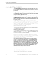
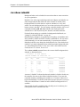
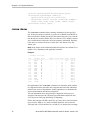
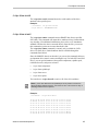
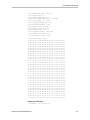
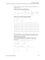
For example,
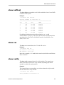
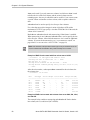
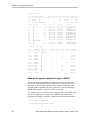
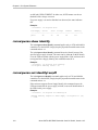
//localhost> show
lists all controllers in the system and shows summary information about
them. For example:
Ctl Model
Ports Drives Units NotOpt RRate VRate BBU
-----------------------------------------------------------c0 9750-4I
4
12
2
0
1
1
c1 9650SE-4
4
4
1
0
3
5 TESTING
c2 7500-12
12
8
3
1
2
-
Using a single command with output
You can use 3ware CLI with line arguments, processing a single command at
a time. To do so, simply type the command and the arguments.
Single commands are useful when you want to perform a task such as
redirecting the output of the command to a file. They also allow you to use the
command line history to reduce some typing.
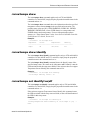
Syntax
tw_cli
<command_line_arguments>
Example
tw_cli /c0 show diag > /tmp/3w_diag.out
www.lsi.com/channel/products
7
Chapter 1. Introduction to the 3ware Command Line Interface
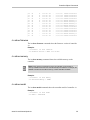
Using an input file to execute a script
You can operate 3ware CLI scripts by executing a file. The file is a text file
containing a list of CLI commands that you have entered in advance. Each
command must be on a separate line.
Syntax
tw_cli -f <filename>
Where <filename> is the name of the text file you want to execute.
Example
tw_cli -f clicommand.txt
This example describes execution of the file clicommand.txt, which runs the
CLI commands included in that file.
Scripting examples
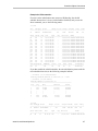
The following scripting example, which is for a four-port controller, uses a
text file called config_unit.text that contains three commands. This example
sets up a four-port controller with two units, each with two drives mirrored.
The last command then prints the configurations for verification. The
following commands are included in the script file:
/c0 add type=raid1 disk=0-1
/c0 add type=raid1 disk=2-3
/c0 show
The following scripting example, which is for a 12-port controller, uses a text
file called config_unit.text that contains three commands. This example sets
up a 12-port controller with two units: one with the first two drives mirrored,
and another with the remaining drives in a RAID 5 array. The last command
then prints the configurations for verification. The following commands are
included in the script file:
/c0 add type=raid1 disk=0-1
/c0 add type=raid5 disk=2-11
/c0 show
To run either of the scripts, type:
tw_cli -f config_unit.txt
8
3ware SATA+SAS RAID Controller Card CLI Guide, Version 10.2
Understanding RAID Levels and Concepts
Outputting the CLI to a Text File
You can send the output of the 3ware CLI, including errors, to a text file by
adding 2>&1 to the end of the line. Outputting to a text file can be useful, for
example, if you want to email the output to LSI Technical Support.
Examples
tw_cli /c2/p0 show >> controller2port0info.txt 2>&1
or
tw_cli /c0 show diag >> Logfile.txt 2>&1
Conventions
The following conventions are used throughout this guide:
•
In text, monospace font is used for code and for things you type.
•
In descriptions and explanations of commands, a bold font indicates the
name of commands and parameters, for example, /c0/p0 show all.
•
In commands, an italic font indicates items that are variable, but that you
must specify, such as a controller ID, or a unit ID, for example, /c0/p0
show attribute, and /cx/px show all
•
In commands, brackets around an item indicate that it is optional.
•
In commands, ellipses (...) indicate that more than one parameter at a time
can be included, for example, /c0/p0 show attribute [attribute ...]
•
In commands, two dots (..) indicate that there is a range between two
values from which you can pick a value, for example, /cx set
carvesize=[1024..2048].
•
In commands, a vertical bar (|) indicates an or situation where you have a
choice between more than one attribute, but only one can be specified.
Example: In the command to rescan all ports and reconstitute all units, the
syntax appears as /cx rescan [noscan]. The brackets [ ] indicate that you can
omit the noscan parameter so that the operation will be reported to the
operating system.
Understanding RAID Levels and Concepts
3ware RAID controllers use RAID (Redundant Array of Independent Disks)
to increase your storage system’s performance and provide fault tolerance
(protection against data loss).
This section includes the following RAID-specific topics:
•
“RAID Concepts”
www.lsi.com/channel/products
9
Chapter 1. Introduction to the 3ware Command Line Interface
•
“Available RAID Configurations” on page 11
•
“Determining Which RAID Level to Use” on page 16
RAID Concepts
The following concepts are important to understand when working with a
RAID controller:
•
Arrays and Units. In the storage industry, an array refers to two or more
disk drives that appear to the operating system as a single unit. When
working with a RAID controller, unit refers to an array of disks that you
can configured and manage through the 3ware software. You can also use
the 3ware software to configure Single-disk units.
•
Mirroring. Mirrored arrays (RAID 1) write data to paired drives
simultaneously. If one drive fails, the data is preserved on the paired
drive. Mirroring provides data protection through redundancy. In
addition, mirroring using a 3ware RAID controller provides improved
performance because the 3ware TwinStor® technology reads from both
drives simultaneously.
•
Striping. Striping across disks allows data to be written and accessed on
more than one drive simultaneously. Striping combines each drive’s
capacity into one large volume. Striped disk arrays (RAID 0) achieve
highest transfer rates and performance at the expense of fault tolerance.
•
Distributed Parity. Parity works in combination with striping on RAID 5,
RAID 6, and RAID 50. Parity information is written to each of the striped
drives, in rotation. If a failure occurs, you can reconstructed the data on
the failed drive from the data on the other drives.
•
Hot Swap. The process of exchanging a drive without shutting down the
system. This process is useful when you need to exchange a defective
drive in a redundant unit.
•
10
Array Roaming. The process of removing a unit from a controller and
putting it back either on the same controller, or a different controller, and
having the unit recognized as a unit. You can attach the disks to different
ports without harm to the data.
3ware SATA+SAS RAID Controller Card CLI Guide, Version 10.2
Understanding RAID Levels and Concepts
Available RAID Configurations
RAID is a method of combining several hard drives into one unit. It can offer
fault tolerance and higher throughput levels than a single hard drive or group
of independent hard drives. LSI's 3ware controllers support RAID 0, 1, 5, 6,
10, 50, and Single Disk. The following information explains the different
RAID levels.
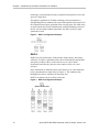
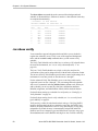
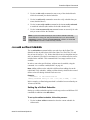
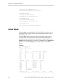
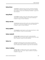
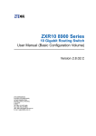
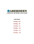
RAID 0
RAID 0 provides improved performance, but no fault tolerance. Because the
data is striped across more than one disk, RAID 0 disk arrays achieve high
transfer rates because they can read and write data on more than one drive
simultaneously. You can configure the stripe size during unit creation.
RAID 0 requires a minimum of two drives.
When drives are configured in a striped disk array (see Figure 1), large files
are distributed across the multiple disks using RAID 0 techniques.
Striped disk arrays give exceptional performance, particularly for dataintensive applications such as video editing, computer-aided design, and
geographical information systems.
RAID 0 arrays are not fault tolerant. The loss of any drive results in the loss of
all the data in that array, and can even cause a system hang, depending on
your operating system. RAID 0 arrays are not recommended for highavailability systems unless you take additional precautions to prevent system
hangs and data loss.
Figure 1. RAID 0 Configuration Example
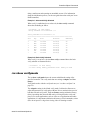
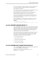
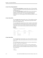
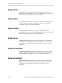
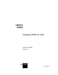
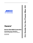
RAID 1
RAID 1 provides fault tolerance and a speed advantage over non-RAID disks.
RAID 1 also is known as a mirrored array. Mirroring is done on pairs of
drives. Mirrored disk arrays write the same data to two different drives using
RAID 1 algorithms (see Figure 2). This gives your system fault tolerance by
preserving the data on one drive if the other drive fails. Fault tolerance is a
basic requirement for critical systems should as web and database servers.
3ware firmware uses a patented TwinStor technology, on RAID 1 arrays for
improved performance during sequential read operations. With TwinStor
www.lsi.com/channel/products
11
Chapter 1. Introduction to the 3ware Command Line Interface
technology, read performance during a sequential read operation is twice the
speed of a single drive.
The adaptive algorithms in TwinStor technology boost performance by
distinguishing between random read request and sequential read requests. For
the sequential read requests generated when accessing large files, both drives
are used with the drive heads simultaneously reading alternating sections of
the file. For the smaller random transactions, the data is read by a single
optimal drive head.
Figure 2. RAID 1 Configuration Example
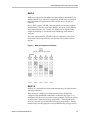
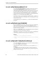
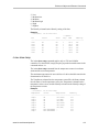
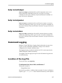
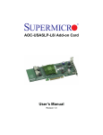
RAID 5
RAID 5 provides performance, fault tolerance, high capacity, and storage
efficiency. It requires a minimum of three drives and combines striping data
with parity (exclusive OR) to restore data in case of a drive failure.
Performance and efficiency increase as the number of drives in a unit
increases.
Parity information is distributed across all of the drives in a unit rather than
being concentrated on a single disk (see Figure 3). This method avoids
throughput loss due to contention for the parity drive.
RAID 5 can tolerate one drive failure in the unit.
Figure 3. RAID 5 Configuration Example
(480 GB - 120 GB for parity)
12
3ware SATA+SAS RAID Controller Card CLI Guide, Version 10.2
Understanding RAID Levels and Concepts
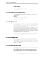
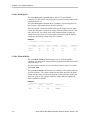
RAID 6
RAID 6 provides greater redundancy and fault tolerance than RAID 5. It is
similar to RAID 5 but, instead of a single block, RAID 6 has two blocks of
parity information (P+Q) distributed across all the drives of a unit (see
Figure 4).
Due to the two parities, a RAID 6 unit can tolerate two hard drives failing
simultaneously. This also means that a RAID 6 unit can be in two different
states at the same time. For example, one subunit can be degraded while
another is rebuilding, or one subunit can be initializing while another is
verifying.
The 3ware implementation of RAID 6 requires a minimum of five drives.
Performance and storage efficiency also increase as the number of drives
increase.
Figure 4. RAID 6 Configuration Example
(600 GB - 240 GB for 2 parity drives)
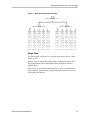
RAID 10
RAID 10 is a combination of striped and mirrored arrays for fault tolerance
and high performance.
When drives are configured as a striped mirrored array, the disks are
configured using both RAID 0 and RAID 1 techniques (see Figure 5). A
minimum of four drives are required to use this technique. The first two drives
are mirrored as a fault-tolerant array using RAID 1. The third and fourth
drives are mirrored as a second fault-tolerant array using RAID 1. The two
mirrored arrays are then grouped as a striped RAID 0 array using a two-tier
www.lsi.com/channel/products
13
Chapter 1. Introduction to the 3ware Command Line Interface
structure. Higher data transfer rates are achieved by leveraging TwinStor
technology and striping the arrays.
In addition, RAID 10 arrays offer a higher degree of fault tolerance than
RAID 1 and RAID 5 because the array can sustain multiple drive failures
without data loss. For example, in a 12-drive RAID 10 array, up to 6 drives
can fail (half of each mirrored pair) and the array continues to function. Note
that if both halves of a mirrored pair in the RAID 10 array fail, all of the data
is lost.
Figure 5. RAID 10 Configuration Example
RAID 50
RAID 50 is a combination of RAID 5 and RAID 0. This array type provides
fault tolerance and high performance. RAID 50 requires a minimum of six
drives.
Several combinations are available with RAID 50. For example, on a 12-port
controller, you can have a grouping of three, four, or six drives. A grouping of
three means that the RAID 5 arrays used have three disks each; four of these
3-drive RAID 5 arrays are striped together to form the 12-drive RAID 50
array. On a 16-port controller, you can have a grouping of four or eight drives.
No more than four RAID 5 subunits are allowed in a RAID 50 unit. For
example, a 24-drive RAID 50 unit may have groups of 12, eight, or six drives,
but not groups of four or three (see Figure 6).
In addition, RAID 50 arrays offer a higher degree of fault tolerance than
RAID 1 and RAID 5, because the array can sustain multiple drive failures
without data loss. For example, in a 12-drive RAID 50 array, one drive in each
RAID 5 set can fail and the array continues to function. Note that if two or
more drives in a RAID 5 set fail, all of the data is lost.
14
3ware SATA+SAS RAID Controller Card CLI Guide, Version 10.2
Understanding RAID Levels and Concepts
Figure 6. RAID 50 Configuration Example
(960 GB - 480 GB for mirror)
(600 GB - 120 GB for parity)
(600 GB - 120 GB for parity)
Single Disk
You can configure a single drive as a unit through 3ware software. (3BM,
3DM2, or CLI).
Similar to disks in other RAID configurations, single disks contain 3ware
Disk Control Block (DCB) information and the OS addresses them as
available units.
Single drives are not fault tolerant and, therefore, are not recommended for
high availability systems unless you take additional precautions to prevent
system hangs and data loss.
www.lsi.com/channel/products
15
Chapter 1. Introduction to the 3ware Command Line Interface
Hot Spare
A hot spare is a single drive, available online, so that a redundant unit is
automatically rebuilt without human intervention in case of drive failure.
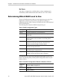
Determining Which RAID Level to Use
The type of RAID unit (array) that you create depends on your needs. You
might want to maximize speed of access, total amount of storage, or
redundant protection of data. Each type of RAID unit offers a different blend
of these characteristics.
The following table summarizes RAID configuration types.
Table 2: RAID Configuration Types
RAID Type
Description
RAID 0
Provides performance, but no fault tolerance.
RAID 1
Provides fault tolerance and a read speed advantage over nonRAID disks.
RAID 5
Provides performance, fault tolerance, and high storage
efficiency. RAID 5 units can tolerate one drive failing before
losing data.
RAID 6
Provides very high fault tolerance with the ability to protect
against two consecutive drive failures. Performance and
efficiency increase with higher numbers of drives.
RAID 10
Provides a combination of striped and mirrored units for fault
tolerance and high performance.
RAID 50
Provides a combination of RAID 5 and RAID 0. RAID 50 provides
high fault tolerance and performance.
Single Disk
Not a RAID type - but supported as a configuration.
Provides maximum disk capacity with no redundancy.
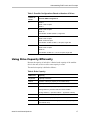
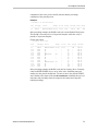
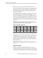
You can create one or more units, depending on the number of drives you
install. The following table provides possible configurations based on your
number of drives.
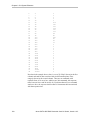
Table 3: Possible Configurations Based on Number of Drives
16
Number of
Drives
Possible RAID Configurations
1
Single disk
2
RAID 0 or RAID 1
3ware SATA+SAS RAID Controller Card CLI Guide, Version 10.2
Understanding RAID Levels and Concepts
Table 3: Possible Configurations Based on Number of Drives
Number of
Drives
Possible RAID Configurations
3
RAID 0
RAID 1 with hot spare
RAID 5
4
RAID 5 with hot spare
RAID 10
Combination of RAID 0, RAID 1, single disk
5
RAID 6
RAID 5 with hot spare
RAID 10 with hot spare
Combination of RAID 0, RAID 1, hot spare, single disk
6 or more
RAID 6
RAID 6 with hot spare
RAID 50
Combination of RAID 0, 1, 5, 6,10, hot spare, single disk
Using Drive Capacity Efficiently
Because the capacity of each drive is limited to the capacity of the smallest
drive in the unit, use drives of the same capacity in a unit.
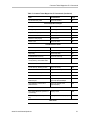
The total unit capacity is defined as follows:
Table 4: Drive Capacity
RAID Level
Capacity
Single Disk
Capacity of the drive
RAID 0
(number of drives) X (capacity of the smallest drive)
RAID 1
Capacity of the smallest drive
RAID 5
(number of drives – 1) X (capacity of the smallest drive)
Storage efficiency increases with the number of disks:
storage efficiency = (number of drives – 1)/(number of drives)
RAID 6
(number of drives – 2) x (capacity of the smallest drive)
RAID 10
(number of drives/2) X (capacity of smallest drive)
RAID 50
(number of drives – number of groups of drives) X (capacity of
the smallest drive)
www.lsi.com/channel/products
17
Chapter 1. Introduction to the 3ware Command Line Interface
Through drive coercion, the capacity used for each drive is rounded down to
improve the likelihood that you can use drives from differing manufactures as
spares for each other. The capacity used for each drive is rounded down to the
nearest GB for drives under 45 GB (45,000,000,000 bytes), and rounded
down to the nearest 5 GB for drives over 45 GB. For example, a 44.3-GB
drive is rounded down to 44 GB, and a 123-GB drive is rounded down to
120 GB.
Note: All drives in a unit must be of the same type, either SAS or SATA.
18
3ware SATA+SAS RAID Controller Card CLI Guide, Version 10.2
2
CLI Syntax Reference
This chapter provides detailed information about using the command syntax
for the 3ware CLI.
Throughout this chapter, the examples shown use the interactive mode of
using the 3ware CLI.
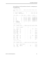
Common Tasks Mapped to CLI Commands
The table below lists many of the tasks that you can use to manage your RAID
controllers and units, and also lists the primary CLI command associated with
those tasks.
Table 5: Common Tasks Mapped to CLI Commands
Task
CLI Command
Page
Controller Configuration Tasks
View information about a controller
/cx show
32
View controller policies and other
details
/cx show [attribute] [attribute]
33
View drive performance statistics
/cx show dpmstat
[type=inst|ra|ext]
36
Set policies for a controller
•
Modify staggered spinup
/cx set stagger and /cx set spinup
68
•
Enable/disable autocarving
/cx set autocarve
68
•
Enable/disable autorebuild
/cx set autorebuild
69
•
Set the autocarve volume size
/cx set carvesize
68
•
Enable/disable drive
performance monitoring
statistics (dpmstat)
/cx set dpmstat
62
Controller Maintenance Tasks
19
3ware SATA+SAS RAID Controller Card CLI Guide, Version 10.2
Chapter 2. CLI Syntax Reference
Table 5: Common Tasks Mapped to CLI Commands (Continued)
Task
CLI Command
Page
Update controller with new
firmware
/cx update
58
Add a time slot to a rebuild
schedule
/cx add rebuild
59
Add a time slot to a verify
schedule
/cx add verify
60
Add a time slot to a selftest
schedule
/cx add selftest
61
Enable/disable the initialize/
rebuild/migrate schedule and set
the task rate
/cx set rebuild
63
Enable/disable the verify schedule
and set the task rate
/cx set verify
65
Set the verify schedule to
advanced or basic
/cx set
verify=advanced|basic|1..5
66
Set the rebuild/migrate task rate
/cx set rebuildrate
64
Set the rebuild/migrate task mode
/cx set rebuildmode
63
Set the verify task rate
/cx set verifyrate
67
Set the verify task mode
/cx set verifymode
66
Set the basic verify start time and
day
/cx set verify=basic [pref=ddd:hh]
66
Enable/disable the selftest
schedule
/cx set selftest
68
View controller alarms (errors,
warnings, messages)
/cx show alarms
43
/cx show events
/cx show AENs
Unit Configuration Tasks
View information about a unit
/cx/ux show
72
Create a unit or hot spare
/cx add
53
Enable/disable unit write cache
/cx/ux set wrcache
81
82
20
Enable Basic or Intelligent read
cache, or disable both.
/cx/ux set rdcache
82
Set the queue policy
/cx/ux set qpolicy
84
Set the rapid RAID recovery policy
/cx/ux set rapidrecovery
84
3ware SATA+SAS RAID Controller Card CLI Guide, Version 10.2
Common Tasks Mapped to CLI Commands
Table 5: Common Tasks Mapped to CLI Commands (Continued)
Task
CLI Command
Page
Set the storsave profile
/cx/ux set storsave
84
Unit Configuration Changes
Change RAID level
/cx/ux migrate
86
Change stripe size
/cx/ux migrate
86
Expand unit capacity
/cx/ux migrate
86
Delete a unit
/cx/ux del
79
Remove a unit (export)
/cx/ux remove
78
Name a unit
/cx/ux set name
83
Unit Maintenance Tasks
Start a rebuild
/cx/ux start rebuild
79
Start a verify
/cx/ux start verify
80
Stop verify
/cx/ux stop verify
80
Enable/disable autoverify
/cx/ux set autoverify
81
Identify all drives that make up a
unit by blinking associated LEDs
/cx/ux set identify
64
Port Tasks
Locate drive by blinking an LED
/cx/px set identify
101
Check if LED is set to on or off
/cx/px show identify
94
View information for specific drive
/cx/px show
92
View the status of specific drive
/cx/px show status
95
Show statistics for the drive on a
particular port
/cx/px show dpmstat
type=inst|ra|lct|histdata|ext
98
Clear statistics counters for a
particular drive
/cx/px set dpmstat=clear
[type=ra|lct|ext]
101
PHY Tasks
View details about link speed for a
specified phy
/cx/phyx show
102
Set the link speed for a specified
phy
/cx/phyx set link=auto|1.5|3.0|6.0
103
BBU Tasks
www.lsi.com/channel/products
21
Chapter 2. CLI Syntax Reference
Table 5: Common Tasks Mapped to CLI Commands (Continued)
Task
CLI Command
Page
Check on charge and condition of
battery
/cx/bbu/ show status
106
Start a test of the battery
/cx/bbu test [quiet]
108
Enclosure Tasks
View information about an
enclosure and its components
/cx/ex show
110
Locate a drive slot in an enclosure
by blinking an LED
/cx/ex/slotx set identify
116
Locate a fan in an enclosure by
blinking an LED
/cx/ex/fanx set identify
117
Set the speed for a fan in an
enclosure
/cx/ex/fanx set speed
117
Locate a power supply in an
enclosure by blinking an LED
/cx/ex/pwrsx set identify
118
Locate a temperature sensor in an
enclosure by blinking an LED
/cx/ex/tempx set identify
119
Turn off or mute an audible alarm
in an enclosure
/cx/ex/almx set alarm
120
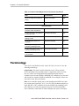
Terminology
3ware SATA+SAS RAID Controller Card CLI Guide, Version 10.2 uses the
following terminology:
Logical Units. This term is usually shortened to units. These are block
devices presented to the operating system. A logical unit can be a one-tier,
two-tier, or three-tier arrangement. Spare and Single logical units are
examples of one-tier units. RAID 1 and RAID 5 are examples of two-tier units
and as such have subunits. RAID 10 and RAID 50 are examples of three-tier
units and, as such, have sub-subunits.
Port. 3ware controller models prior to and including the 9650SE series have
one or many ports (typically 4, 8, 12, 16, or 24). You can attach each port to a
single disk drive. On a controller such as the 9650SE with a multilane serial
port connector, one connector supports four ports. On 9750 and 9690SA
series controllers, connections are made with phys and vports (virtual port).
22
3ware SATA+SAS RAID Controller Card CLI Guide, Version 10.2
Syntax Overview
Phy. Phys are transceivers that transmit and receive the serial data stream that
flows between the controller and the drives. 3ware 9750 and 9690SA
controllers have four or more phys. These controller phys are associated with
virtual ports (vports) by 3ware software to establish up to 128 potential
connections with SAS or SATA hard drives. You can connect each controller
phy directly to a single drive, or you can connect it through an expander to
additional drives.
VPort. Connections from 3ware 9750 and 9690SA controllers to SAS or
SATA drives are referred to as virtual ports, or VPorts. A VPort indicates the
ID of a drive, whether it connects directly to the controller or cascades
through one or more expanders. The VPort, in essence, is a handle in the
software to uniquely identify a drive. The VPort ID or port ID allows a drive
to be consistently identified, used in a RAID unit, and managed. For dual-port
drives, although there are two connections to a drive, the drive is still
identified with one VPort handle.
Note: For practical purposes, port and VPort are used interchangeably in this
document in reference to a drive (or disk). Therefore, unless otherwise specified,
the mention of port implies VPort as well. For example, when port is used to indicate
a drive, it is implied that, for the applicable controller series, the reference also
applies to VPort.
For additional information about 3ware controller concepts and terminology,
refer to the user guide PDF for your 3ware RAID controller or the user guide
portions of the 3ware HTML Bookshelf.
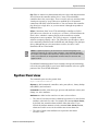
Syntax Overview
The command syntax uses the general form:
Object Command Attributes
Objects are shell commands, controllers, units, ports (drives), battery backup
units (BBUs), and enclosures.
Commands can either select (show, get, present, read) attributes or alter (add,
change, set, write) attributes.
Attributes are either boolean attributes or name-value attributes.
•
The value of a boolean attribute is deduced by presence of a value for that
attribute, or the lack of a value. For example, the command show alarms,
by default, lists controller alarms with the oldest alarm first. If you
include the attribute reverse, as in the command show alarms reverse,
alarms are listed in reverse order with the most recent alarm first.
•
The value of name-value attributes are expressed in the format
attribute=value.
www.lsi.com/channel/products
23
Chapter 2. CLI Syntax Reference
Example: When adding (creating) a unit to the controller by using the
following command string,
/c1 add type=raid1 disk=0-1
c1 is the object, add is the command, type (for type of array) is an attribute
with raid1 as the value of the attribute, and disk is another attribute with
0-1 as the value (ports 0 through 1).
Commands act on different objects, for example shell objects, controller
objects, unit objects, and other objects. Information about these commands is
organized into sections about each object.
Shell Object Commands. Shell object commands set the focus or provide
information (such as alarms, diagnostics, rebuild schedules, and other
functions) about all controllers in the system. For details, see “Shell Object
Commands” on page 25.
Controller Object Commands. Controller object commands provide
information and perform actions related to a specific controller. For example,
you use controller object commands for such tasks as viewing a list of alarms
specific to a controller, creating schedules during which background tasks are
run, and setting policies for the controller. You can also use the controller
object command /cx add to create RAID arrays. For details, see “Controller
Object Commands” on page 30.
Unit Object Commands. Unit object commands provide information and
perform actions related to a specific unit on a specific controller. You can use
unit object commands for a number of tasks, for example, to see the rebuild
verify, or initialize status of a unit; to start or stop verifies; to start rebuilds; to
set policies for the unit, and to perform other tasks related to the unit. You also
use the controller object command
/cx/ux migrate to change the configuration of a RAID array. For details, see
“Unit Object Commands” on page 71.
Phy Object Commands. Phy object commands provide information and
perform actions related to a specific phy on a 9750 or 9690SA controller.
Port Object Commands. Port object commands provide information and
perform actions related to a drive on a specific port or vport. You can use port
object commands for such tasks as viewing the status, model, or serial number
of the drive. For details, see “Port Object Commands” on page 92.
BBU Object Commands. BBU object commands provide information and
perform actions related to a Battery Backup Unit on a specific controller. For
details, see “BBU Object Commands” on page 103.
Enclosure Object Commands. Enclosure object commands provide
information and perform actions related to a particular enclosure. For
example, you can use enclosure object commands to see information about an
enclosure and its elements (slots, fan, and temperature sensor elements).
24
3ware SATA+SAS RAID Controller Card CLI Guide, Version 10.2
Shell Object Commands
Help Commands. Help commands allow you to get help information for all
commands and attributes. For details, see “Help Commands” on page 122.
Shell Object Commands
Shell object commands either apply to all the controllers in the system (such
as show, rescan, flush, commit), or they redirect the focused object.
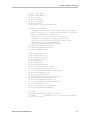
Syntax
focus object
commit
flush
rescan
show [attribute [modifier]]
alarms [reverse]
diag
rebuild
selftest
ver
verify
update fw=filename_with_path [force]
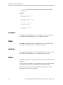
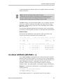
focus Object
The focus command is active in interactive mode only and is provided to
reduce typing.
The focus command sets the specified object in focus and changes the prompt
to reflect the specified object. This allows you to type a command that applies
to the specified object instead of typing the entire object name each time.
For example, where normally you might type:
/c0/u0 show
If you set the focus to /c0/u0, the prompt changes to reflect /c0/u0, and you
only have to type show. The concept is similar to working in a particular
location in a file system and requesting a listing of the current directory.
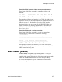
When you type the command focus /object, object can have the following
forms:
•
specifies the fully qualified Universal Resource Identifier (URI)
of an object on controller cx, unit ux.
•
..
(two trailing periods) specifies one level up (the parent object).
•
/
(a forward slash) specifies the root
•
object specifies the next level of the object.
/cx/ux
www.lsi.com/channel/products
25
Chapter 2. CLI Syntax Reference
•
specifies a relative path with respect to the current focused
hostname.
/c0/bbu
Example:
//localhost> focus /c0/u0
//localhost/c0/u0>
//localhost/c0/u0> focus..
//localhost/c0>
//localhost> focus u0
//localhost/c0/u0>
//localhost/c0> focus /
//localhost>
commit
The commit command sends a commit command to all 3ware controllers in
the system. For more information, see “/cx commit” on page 58.
flush
The flush command sends a flush command to all 3ware controllers in the
system. For more information, see “/cx flush” on page 58.
rescan
The rescan command sends a rescan command to all 3ware controllers in the
system. For more information, see “/cx rescan [noscan]” on page 57.
show
The show command shows a general summary of all detected controllers and
enclosures.
The output of this command can vary depending upon your controller model
and whether the system has an enclosure with an expander attached.
Note that the device drivers for the appropriate operating system must be
loaded for the list to show all controllers.
26
3ware SATA+SAS RAID Controller Card CLI Guide, Version 10.2
Shell Object Commands
Example for 9750-8i controller without an enclosure and expander:
Typical output of the Show command for a controller is similar to the
following:
//localhost> show
Ctl
Model
(V)Ports Drives
Units
NotOpt RRate
VRate BBU
-----------------------------------------------------------------------c0
9750-8i
8
8
2
0
1
1
-
The output above indicates that Controller 0 is a 9750-8i with eight (V)ports,
eight drives detected, two units, both in optimal state, with rebuild rate set to 1
and verify rate set to 1. This controller does not have a BBU attached.
Not Optimal refers to any state except OK and VERIFYING. RRate also
applies to initializing and migrating. (Definitions of the unit statuses are
available in the 3ware SATA+SAS RAID Controller Card Software User
Guide, Version 10.2.)
Example for 9750-8e with an enclosure attached:
Typical output of the Show command for a system with an enclosure,
expander, and a 9750-8e controller is similar to the following:
//localhost> show
Ctl
Model
(V)Ports Drives
Units
NotOpt RRate
VRate BBU
-----------------------------------------------------------------------c1
9750-8e
23
23
3
0
1
1
OK
Enclosure
Slots Drives Fans TSUnits PSUnits Alarms
-------------------------------------------------------------/c1/e0
24
23
4
6
2
2
The output above indicates that Controller 1 is a 9750-8e with 23 drives
attached, with 3 units in optimal state, rebuild and verify rate set to 1, and with
a BBU in normal and ready state.
show alarms [reverse]
The show alarms command shows the controller alarms or events, also
known as Asynchronous Event Notification (AEN) messages, of all
controllers in the system. The default is to list the most recent messages at the
bottom. The reverse attribute lists the most recent message at the top.
To view this information for a specific controller, see “/cx show alarms
[reverse]” on page 43.
www.lsi.com/channel/products
27
Chapter 2. CLI Syntax Reference
show events [reverse]
The show events command is the same as “show alarms [reverse]”. Please see
above for details.
show AENs [reverse]
The show AENS command is the same as “show alarms [reverse]”. Please see
above for details.
show diag
The show diag command shows the diagnostic information for all controllers
in the system. The enclosure diagnostic log might be requested by 3ware
Customer Support to troubleshoot problems on your controller.
show rebuild
The show rebuild command shows all rebuild schedules for the 3ware RAID
controllers in the system.
Example:
//localhost> show rebuild
Rebuild Schedule for Controller /c0
========================================================
Slot
Day
Hour
Duration
Status
-------------------------------------------------------1
Sun
12:00am
24 hr(s)
disabled
2
Mon
12:00am
24 hr(s)
disabled
3
Tue
12:00am
24 hr(s)
disabled
4
Wed
12:00am
24 hr(s)
disabled
5
Thu
12:00am
24 hr(s)
disabled
6
Fri
12:00am
24 hr(s)
disabled
7
Sat
12:00am
24 hr(s)
disabled
For additional information about rebuild schedules, see “/cx add
rebuild=ddd:hh:duration” on page 59, and refer to the discussion of
background tasks and schedules in 3ware SATA+SAS RAID Controller Card
Software User Guide, Version 10.2.
28
3ware SATA+SAS RAID Controller Card CLI Guide, Version 10.2
Shell Object Commands
show selftest
The show selftest command shows all selftest schedules for the 3ware RAID
controllers in the system.
Example:
//localhost> show selftest
Selftest Schedule for Controller /c0
========================================================
Slot
Day
Hour
SMART
-------------------------------------------------------1
Sun
12:00am
enabled
2
Mon
12:00am
enabled
3
Tue
12:00am
enabled
4
Wed
12:00am
enabled
5
Thu
12:00am
enabled
6
Fri
12:00am
enabled
7
Sat
12:00am
enabled
For additional information about selftest schedules, see “/cx add
selftest=ddd:hh” on page 61, and refer to the discussion of background tasks
and schedules in 3ware SATA+SAS RAID Controller Card Software User
Guide, Version 10.2.
show ver
The show ver command shows the CLI and API version.
Example:
//localhost> show ver
CLI Version = 2.00.03.0xx
API Version = 2.01.00.xx
In the above example, “xx” stands for the actual version. Refer to the Release
Notes for details.
show verify
The show verify command shows all verify schedules. The output shows
either the advanced or the basic verify schedule, depending upon which
schedule is enabled for each controller.
Example:
This example shows two controllers, one with an advanced verify schedule
and one with a basic verify schedule.
//localhost> show verify
Verify Schedule for Controller /c2
www.lsi.com/channel/products
29
Chapter 2. CLI Syntax Reference
========================================================
Slot
Day
Hour
Duration
AdvVerify
-------------------------------------------------------1
Sun
12:00am
24 hr(s)
on
2
Mon
12:00am
24 hr(s)
on
3
Wed
4:00pm
24 hr(s)
on
4
Wed
12:00am
24 hr(s)
on
5
Thu
12:00am
24 hr(s)
on
6
Fri
12:00am
24 hr(s)
on
7
Sat
12:00am
24 hr(s)
on
/c3 basic verify weekly preferred start: Saturday, 12:00AM
For additional information about verify schedules, see “/cx add
verify=ddd:hh:duration” on page 60, “/cx set verify=basic [pref=ddd:hh]” on
page 66, and refer to the discussion of background tasks and schedules in
3ware SATA+SAS RAID Controller Card Software User Guide, Version 10.2.
update fw=filename_with_path [force]
The update fw command downloads the specified firmware image to the
controllers that are compatible with the firmware image and iterates through
all the controllers in the system, updating the firmware. For more information,
see “/cx update fw=filename_with_path [force]” on page 58.
Controller Object Commands
Controller object commands provide information and perform actions related
to a specific controller, such as /c0. For example, you use controller object
commands to view a list of alarms specific to a controller, to create schedules
for when background tasks are run, and to set policies for the controller. You
also use the controller object command /cx add type to create RAID arrays.
Syntax
/cx show
/cx show attribute [attribute ...] where attributes are:
achip|allunitstatus|autocarve|autorebuild|bios|
carvesize|ctlbus|dpmstat[type=inst|ra|ext]|driver|
drivestatus|firmware|memory|model|monitor|numdrives|
numports|numunits|pcb|pchip|serial|spinup|stagger|
unitstatus|
/cx show all (where all means attributes and configurations)
/cx show diag
/cx show alarms [reverse]
/cx show events [reverse]
/cx show AENS [reverse]
/cx show rebuild
30
3ware SATA+SAS RAID Controller Card CLI Guide, Version 10.2
Controller Object Commands
/cx
/cx
/cx
/cx
/cx
/cx
/cx
show
show
show
show
show
show
show
rebuildmode
rebuildrate
verify
verifymode
verifyrate
selftest
phy (9750 and 9690SA only)
/cx add type=<RaidType>
(RaidType={raid0,raid1,raid5,raid6,raid10,raid50,single,
spare}) disk=<p:-p..> [stripe=<Stripe>][noscan][nocache|
nowrcache][nordcache|rdcachebasic]
[group=<3|4|5|6|7|8|9|10|11|12|13|14|15|16>]
[autoverify][noqpolicy][ignorECC][name=string](
[v0=n|vol=a:b:c:d](n=size of first volume in GB)
[rapidrecovery=all|rebuild|disable]
[storsave=<protect|balance|perform>]
/cx add rebuild=ddd:hh:duration
/cx add verify=ddd:hh:duration
/cx add selftest=ddd:hh
/cx
/cx
/cx
/cx
/cx
/cx
/cx
/cx
/cx
/cx
/cx
/cx
/cx
/cx
/cx
/cx
/cx
/cx
/cx
del
del
del
set
set
set
set
set
set
set
set
set
set
set
set
set
set
set
set
/cx
/cx
/cx
/cx
flush
update fw=filename_with_path [force]
commit
(Windows only. Also known as shutdown)
rescan [noscan]
www.lsi.com/channel/products
rebuild=slot_id
verify=slot_id
selftest=slot_id
dpmstat=on|off
spinup=nn
stagger=nn
autocarve=on|off
carvesize=[1024...32768]
rebuild=enable|disable|1..5
rebuildmode=<adaptive|lowlatency>
rebuildrate=<1..5>
autorebuild=on|off
autodetect=on|off disk=<p:-p>|all
verify=enable|disable|1..5
verify=advanced|basic|1..5
verifymode=<adaptive|lowlatency>
verifyrate=<1..5>
verify=basic [pref=ddd:hh]
selftest=enable|disable
31
Chapter 2. CLI Syntax Reference
/cx show
The /cx show command shows summary information on the specified
controller /cx. This information is organized into a report containing two or
three parts:
•
A Unit summary section listing all present units
•
A Port summary section listing of all ports (or virtual ports) and disks
attached to them.
•
A BBU summary section listing, if a BBU is installed on the controller.
The Unit summary section lists all present units and, for each one, specifies
their unit number, unit type (such as RAID 5), unit status (such as
INITIALIZING), %R (percent completion of rebuilding), % V/I/M (percent
completion of verifying, initializing, or migrating), stripe size, size (usable
capacity) in gigabytes, the write cache setting, the read cache setting (if
supported by your controller) and the autoverify policy status (on/off)
Possible unit statuses include OK, RECOVERY, INOPERABLE,
UNKNOWN, DEGRADED, INITIALIZING, INIT-PAUSED, VERIFYING,
VERIFY-PAUSED, REBUILDING, REBUILD-PAUSED, MIGRATING, and
MIGRATE-PAUSED. Definitions of the unit statuses are available in the
3ware SATA+SAS RAID Controller Card Software User Guide, Version 10.2.
Note: An asterisk (*) next to the status of a unit indicates there is an error on one of
the drives in the unit. This feature provides a diagnostic capability for potential
problem drives. The error might not be a repeated error, and might be caused by an
error correction code (ECC) error, Smart Monitoring Analysis and Reporting
(SMART) failure, or a device error. Rescanning the controller clears the drive error
status if the condition no longer exists.
For controllers with read cache support, the Cache column shows the settings
of both the read cache and the write cache.
Below is a summary of the possible settings in the Cache column:
W – only the write cache is enabled
Rb – only the read cache Basic Mode is enabled
Ri – only the read cache Intelligent Mode is enabled
RbW – the read cache Basic Mode and the write cache are both enabled
RiW – the read cache Intelligent Mode and the write cache are both enabled
OFF – all caches are disabled
Note that when the Intelligent Mode of the read cache is enabled, the Basic
Mode features are also enabled. For details, see “/cx/ux set
rdcache=basic|intelligent|off” on page 82.
This section lists the ports or virtual ports present, and for each port, specifies
the port or vport number, drive status, unit affiliation, drive type, phy number
32
3ware SATA+SAS RAID Controller Card CLI Guide, Version 10.2
Controller Object Commands
( if direct attached), the enclosure and slot (if expander attached), and model
number of the drive.
Note: If a drive is not present, that port entry is not listed.
Consequently, the port numbers in the list might not be sequential. Moreover, if
there are no drives present for the specified controller, the output of its Port
summary shows an empty summary consisting of only the header
The BBU summary lists details about the BBU, if one is installed. It lists the
online state, readiness, and status of the BBU unit, along with the voltage,
temperature, charge capacity expressed as time remaining in hours, and the
BBU's last test date..
You can obtain additional attributes about controllers, units, ports and disks
by querying for them explicitly. For details, see the other show subcommands.
Example output:
Note that the port information is represented by VPort (virtual port) and
Cache is represented by both Read Cache and Write cache.
Unit UnitType Status
%RCmpl %V/I/M Stripe Size(GB) Cache AVrfy
--------------------------------------------------------------------------u0
SPARE
OK
149.042
OFF
u1
Single
OK
149.051
RiW
OFF
VPort Status
Unit
Size
Type Phy Encl-Slot
Model
--------------------------------------------------------------------------p0
OK
149.05 GB SATA 3
WDC WD1600JS-22NCB1
p1
OK
u0
149.05 GB SATA 0
WDC WD1600JS-22NCB1
p2
OK
u1
149.05 GB SATA 2
WDC WD1600JS-22NCB1
p3
OK
34.18 GB SAS
6
SEAGATE ST936701SS
/cx show attribute [attribute ...]
The /cx show attribute command shows the current setting of the specified
attributes on the specified controller. You can specify one or many attributes.
If you specify an invalid attribute, the loop terminates. Possible attributes are:
achip, allunitstatus, autocarve , autorebuild , bios, carvesize , driver,
drivestatus, firmware, memory, model, monitor, numdrives, numports,
numunits, ctlbus , pcb, pchip, qpolicy, serial, spinup, stagger, and unitstatus.
Example: To view the driver and firmware version installed on controller 0,
type the following:
//localhost> /c0 show driver firmware
/c0 Driver Version = 2.x
/c0 Firmware Version = FE9X 3.x
(In the sample output above, x represents the actual version number.)
www.lsi.com/channel/products
33
Chapter 2. CLI Syntax Reference
/cx show achip
The /cx show achip command shows the SAS+SATA I/O controller (IOC)
version of the specified controller /cx.
Example:
//localhost> /c0 show achip
/c0 ACHIP Version = 3.x
/cx show allunitstatus
The /cx show allunitstatus command presents a count of total and Not
Optimal units managed by the specified controller /cx.
Example:
//localhost> /c0 show allunitstatus
/c0 Total Optimal Units = 2
/c0 Not Optimal Units = 0
/cx show autocarve
The /cx show autocarve command shows the Autocarve policy. If the policy
is on, all newly created or migrated units larger than the carvesize are
automatically carved into multiples of carvesize volumes plus one remainder
volume. You can treat each volume as an individual drive with its own file
system. The default carvesize is 2 TB. For more information see, “/cx show
memory” on page 39.
For operating systems that support units larger than 2 TB, do not set the policy
to on unless you want the operating system to have multiple smaller volumes.
If you use a 32-bit operating system, it is best to keep the policy on unless
your operating system supports disks larger than 2 TB.
When the Autocarve policy is off, all newly created units consist of one single
volume.
Example:
//localhost> /c0 show autocarve
/c0 Autocarving Policy = on
/cx show autorebuild
The /cx show autorebuild command shows the Autorebuild policy. If you
enable the policy, the firmware selects drives to use for rebuilding a degraded
unit by using the following priority order. For more information, see “/cx set
autorebuild=on|off” on page 69.
1. Smallest usable spare.
2. Smallest usable unconfigured (available) drive.
34
3ware SATA+SAS RAID Controller Card CLI Guide, Version 10.2
Controller Object Commands
3. Smallest usable failed drive.
If the policy is disabled, only spare drives are used for an automatic rebuild
operation.
Example:
//localhost> /c0 show autorebuild
/c0 Auto-Rebuild Policy = on
/cx show bios
The /cx show bios command shows the BIOS version of controller /cx.
Example:
//localhost> /c0 show bios
/c0 BIOS Version = BG9X 2.x
/cx show carvesize
The /cx show carvesize command shows the maximum size of the volumes
that can be created if the autocarve policy is set to on. You can set the
carvesize between 1024 GB and 32768 GB (1 TB to 32 TB). Default
carvesize is 2048 GB (2 TB). For more information see, “/cx show autocarve”
on page 34.
Example:
//localhost> /c0 show carvesize
/c0 Autocarving Size = 2000 GB
/cx show ctlbus
The /cx show ctlbus command shows the controller host bus type, bus speed,
and bus width.
Example for 9690SA:
//localhost> /c2 show ctlbus
/c2 Controller Bus Type = PCIe
/c2 Controller Bus Width = 8 lanes
/c2 Controller Bus Speed = 2.5 Gbps/lane
/cx show driver
The /cx show driver command shows the device driver version associated
with controller
/cx.
Example:
//localhost> /c0 show driver
/c0 Driver Version = 3.x
www.lsi.com/channel/products
35
Chapter 2. CLI Syntax Reference
/cx show dpmstat [type=inst|ra|ext]
The /cx show dpmstat command shows the configuration and setting of the
Drive Performance Monitor and a summary of statistics for drives attached to
the controller.
The optional type attribute specifies which statistics are reported. The
available options are: inst for Instantaneous, ra for Running Average, and ext
for Extended Drive Statistics. If you do not specify a type, you see the default
set of drive statistics, which is the type inst.
inst (Instantaneous). This measurement provides a short duration average.
ra (Running Average). Running average is a measure of long-term averages
that even out the data, which results in older measurement results fading from
the average over time.
ext (Extended Drive Statistics). The extended drive statistics refers to
statistics of a drive's read commands, write commands, write commands with
Force Unit Access (FUA), flush commands, and a drive sectors's read, write,
and write commands with FUA. Additional statistics are available for drives
at specific ports. For details, see “/cx/px show dpmstat
type=inst|ra|lct|histdata|ext” on page 98.
You can turn Drive Performance Monitoring on and off using the command
“/cx set dpmstat=on|off” on page 62.
Example of inst drive statistics:
To view a summary of instantaneous data for the set of drives attached to the
controller, use command /cx show dpmstat. (Because inst is the default, you
do not have to explicitly type it in the command).
Because this is a controller-level command, the output provides summary
information for the set of drives attached to the controller. For statistics about
a drive attached to a specific port, see “/cx/px show dpmstat
type=inst|ra|lct|histdata|ext” on page 98.
In the configuration information shown below, the Performance Monitor is
shown to be ON, Version refers to the firmware version of the Performance
Monitor, Max commands for averaging refers to the maximum number of
commands that can be saved and used for calculating the average, and Max
latency commands to save refers to the maximum number of commands with
high latency that are saved. These configurations and the amount of memory
in the system determine the amount of statistics data in the buffer. These
configuration settings cannot be changed at this time.
//localhost> /c0 show dmpstat
Drive Performance Monitor Configuration for /c0 ...
Performance Monitor: ON
Version: 1
Max commands for averaging: 100
Max latency commands to save: 10
Requested data: Instantaneous Drive Statistics
36
3ware SATA+SAS RAID Controller Card CLI Guide, Version 10.2
Controller Object Commands
Queue
Xfer
Resp
Port
Status
Unit
Depth
IOPs
Rate(MB/s)
Time(ms)
-------------------------------------------------------------p0
NOT-PRESENT p1
NOT-PRESENT p2
OK
p3
OK
u0
10
93
2.907
85
p4
OK
u1
10
84
2.640
95
p5
OK
p6
NOT-PRESENT p7
NOT-PRESENT -
Example of running average (ra) drive statistics:
To view a summary of the running average data for the set of drives attached
to the controller, use command /cx show dpmstat type=ra.
Notice that in this case, the Performance Monitor is turned off.
//localhost> /c0 show dpmstat type=ra
Drive Performance Monitor Configuration for /c0 ...
Performance Monitor: OFF
Version: 1
Max commands for averaging: 100
Max latency commands to save: 10
Requested data: Running Average Drive Statistics
Queue
Xfer
Resp
Port
Status
Unit
Depth
IOPs
Rate(MB/s)
Time(ms)
-----------------------------------------------------------------------p0
NOT-PRESENT
p1
NOT-PRESENT
p2
OK
p3
OK
u0
0
435
25.249
2
p4
OK
u1
0
366
21.630
3
p5
OK
p6
NOT-PRESENT
p7
NOT-PRESENT
-
Example of extended drive statistics (ext):
To view a summary of the extended drive statistics associated with the
specified controller, use command /cx show dpmstat type=ext.
//localhost> /c3 show dpmstat type=ext
Extended Drive Statistics for /c3 ...
Sectors
Commands
---------------------------------- --------------------------------------Port
Read
Write
Write-FUA Read
Write
Write-FUA Flush
--------------------------------------------------------------------------p0
28704384 0
28704384
28704448 0
0
0
p2
28704384 28704448 0
0
0
0
0
p3
28704704 0
0
0
0
0
0
www.lsi.com/channel/products
37
Chapter 2. CLI Syntax Reference
p6
0
0
0
0
0
0
0
Note: Depending on the amount of I/O and the rate or duration of the data
transfer, overflow of the buffers containing this data can occur. In this case,
the overflow is marked with “#######”, as shown in the example below. If
overflow occurs, you might want to return the counters to zero by using the
clear command, “/cx/px set dpmstat=clear [type=ra|lct|ext]” on page 101.
Example of drive statistics overflow:
//localhost> /c3 show dpmstat type=ext
Extended Drive Statistics for /c3 ...
Sectors
Commands
----------------------------------- -------------------------------------Port
Read
Write
Write-FUA Read
Write
Write-FUA Flush
--------------------------------------------------------------------------p0
######## 0
158838656 158838720 0
0
0
p2
######## ######## ########
######## ######## ########
########
p3
######## 0
0
0
0
0
0
p6
0
0
0
0
0
0
0
/cx show drivestatus
The /cx show drivestatus command shows a list of drives and their port
assignment, status, the unit with which they are associated, their size in
gigabytes and blocks, and the serial number assigned by the drive
manufacturer. (Definitions of the drive statuses are available in the 3ware
SATA+SAS RAID Controller Card Software User Guide, Version 10.2.)
Example:
//localhost> /c2 show drivestatus
VPort Status
Unit Size
Type Phy Encl-Slot
Model
-------------------------------------------------------------------------p0
OK
u0
34.25 GB SAS
/c2/e0/slt0 MAXTOR ATLAS15K2_36
p1
OK
u0
34.25 GB SAS
/c2/e0/slt1 MAXTOR ATLAS15K2_36
p2
OK
u0
34.25 GB SAS
/c2/e0/slt2 MAXTOR ATLAS15K2_36
p3
OK
u0
34.18 GB SAS
/c2/e1/slt0 HITACHI HUS151436VL
p4
OK
u0
34.18 GB SAS
/c2/e1/slt1 HITACHI HUS151436VL
p5
OK
u0
34.18 GB SAS
/c2/e1/slt2 HITACHI HUS151436VL
p6
OK
u0
34.25 GB SAS
/c2/e0/slt3 MAXTOR ATLAS15K2_36
p7
OK
u0
34.25 GB SAS
/c2/e0/slt4 MAXTOR ATLAS15K2_36
p8
OK
u0
34.25 GB SAS
/c2/e0/slt5 MAXTOR ATLAS15K2_36
p9
OK
u0
34.25 GB SAS
/c2/e0/slt6 MAXTOR ATLAS15K2_36
p10
OK
u0
34.18 GB SAS
/c2/e1/slt3 HITACHI HUS151436VL
p11
OK
u0
34.18 GB SAS
/c2/e1/slt4 HITACHI HUS151436VL
p12
OK
u0
34.18 GB SAS
/c2/e1/slt5 HITACHI HUS151436VL
p13
OK
u0
34.18 GB SAS
/c2/e1/slt6 HITACHI HUS151436VL
p14
OK
u0
34.25 GB SAS
/c2/e0/slt7 MAXTOR ATLAS15K2_36
p15
OK
u0
34.25 GB SAS
/c2/e0/slt8 MAXTOR ATLAS15K2_36
p16
OK
u0
34.25 GB SAS
/c2/e0/slt9 MAXTOR ATLAS15K2_36
p17
OK
u0
34.25 GB SAS
/c2/e0/slt10 MAXTOR ATLAS15K2_36
38
3ware SATA+SAS RAID Controller Card CLI Guide, Version 10.2
Controller Object Commands
p18
p19
p20
p21
p22
p23
p24
p25
p26
p27
p28
p29
p30
p31
OK
OK
OK
OK
OK
OK
OK
OK
OK
OK
OK
OK
OK
OK
u0
u0
u0
u0
u0
u0
-
34.18
34.18
34.18
34.18
34.25
34.25
34.25
34.25
34.18
34.18
34.18
34.18
34.25
34.18
GB
GB
GB
GB
GB
GB
GB
GB
GB
GB
GB
GB
GB
GB
SAS
SAS
SAS
SAS
SAS
SAS
SAS
SAS
SAS
SAS
SAS
SAS
SAS
SAS
-
/c2/e1/slt7
/c2/e1/slt8
/c2/e1/slt9
/c2/e1/slt10
/c2/e0/slt11
/c2/e0/slt12
/c2/e0/slt13
/c2/e0/slt14
/c2/e1/slt11
/c2/e1/slt12
/c2/e1/slt13
/c2/e1/slt14
/c2/e0/slt15
/c2/e1/slt15
HITACHI HUS151436VL
HITACHI HUS151436VL
HITACHI HUS151436VL
HITACHI HUS151436VL
MAXTOR ATLAS15K2_36
MAXTOR ATLAS15K2_36
MAXTOR ATLAS15K2_36
MAXTOR ATLAS15K2_36
HITACHI HUS151436VL
HITACHI HUS151436VL
HITACHI HUS151436VL
HITACHI HUS151436VL
MAXTOR ATLAS15K2_36
HITACHI HUS151436VL
/cx show firmware
The /cx show firmware command shows the firmware version of controller
/cx.
Example:
//localhost> /c0 show firmware
/c0 Firmware Version = FE9X 3.03.06.X03
/cx show memory
The /cx show memory command shows the available memory on the
controller.
Note: Some memory is reserved for use by the controller, so the amount of
memory available is less than the controller actually has installed. For example, the
9690SA controller has 512 MB of memory, of which 448 MB is available.
Example:
//localhost> /c2 show memory
/c2 Available Memory = 448MB
/cx show model
The /cx show model command shows the controller model of controller /cx.
Example:
//localhost> /c0 show model
/c0 Model = 9690SA-8E
www.lsi.com/channel/products
39
Chapter 2. CLI Syntax Reference
/cx show monitor
The /cx show monitor command shows the monitor (firmware boot-loader)
version of controller /cx.
Example:
//localhost> /c0 show monitor
/c0 Monitor Version = BLDR 2.x
/cx show numdrives
The /cx show numdrives command shows the number of drives currently
managed by the specified controller /cx. This report does not include
(logically) removed or exported drives.
Example:
//localhost> /c0 show numdrives
/c0 Number of Drives = 5
/cx show numports
The /cx show numports command shows the total number of physical
connections made to the controller and the maximum connections possible for
the controller.
Example for a 9650SE-16ML with no drives attached:
//localhost> /c0 show numports
/c0 Number of Ports = 16
Example for 9690SA-8E with 8 dual-port SAS drives:
//localhost> /c3 show numports
/c3 Connections = 16 of 128
/cx show numunits
The /cx show numunits command shows the number of units currently
managed by the specified controller /cx. This report does not include off-line
units (or removed units).
Example:
//localhost> /c0 show numunits
/c0 Number of Units = 1
/cx show pcb
The /cx show pcb command shows the Printed Circuit Board (PCB) version
of the specified controller /cx.
Example:
//localhost> /c0 show pcb
/c0 PCB Version = RevX
40
3ware SATA+SAS RAID Controller Card CLI Guide, Version 10.2
Controller Object Commands
/cx show pchip
The /cx show pchip command shows the PCI Interface Chip (PCHIP) version
of the specified controller /cx.
Example:
//localhost> /c0 show pchip
/c0 PCHIP Version = 1.x
/cx show serial
The /cx show serial command shows the serial number of the specified
controller /cx.
Example:
//localhost> /c0 show serial
/c0 Serial Number = F12705A3240009
/cx show spinup
The /cx show spinup command shows the number of concurrent SAS and
SATA disks that spin up when the system is powered up, after waiting for the
number of seconds specified with the set stagger command. Spinup does
not work with SAS or SATA disks attached to an expander.
Example:
//localhost> /c0 show spinup
/c0 Disk Spinup Policy = 1
/cx show stagger
The /cx show stagger command shows the time delay between each group of
spinups at power up. Spinup does not work with SAS or SATA disks attached
to an expander.
Example:
//localhost> /c0 show stagger
/c0 Spinup Stagger Time Policy (sec) = 2
/cx show unitstatus
The /cx show unitstatus command presents a list of units currently managed
by the specified controller /cx, and shows their types, capacity, status, and unit
policies.
Possible statuses include: OK, VERIFYING, VERIFY-PAUSED,
INITIALIZING, INIT-PAUSED, REBUILDING, REBUILD-PAUSED,
DEGRADED, MIGRATING, MIGRATE-PAUSED, RECOVERY,
INOPERABLE, and UNKNOWN. (Definitions of the unit statuses are
www.lsi.com/channel/products
41
Chapter 2. CLI Syntax Reference
available in the 3ware SATA+SAS RAID Controller Card Software User
Guide, Version 10.2.)
Note: If an asterisk (*) appears next to the status of a unit, there is an error on one
of the drives in the unit. This feature provides a diagnostic capability for potential
problem drives. The error might not be a repeated error, and can be caused by an
ECC error, SMART failure, or a device error. Rescanning the controller clears the
drive error status when the condition no longer exists.
Example:
//localhost> /c2 show unitstatus
Unit UnitType Status
%RCmpl %V/I/M Stripe Size(GB) Cache AVrfy
------------------------------------------------------------------------u0
RAID-5
OK
64K
596.004
ON
OFF
u1
RAID-0
OK
64K
298.002
ON
OFF
u2
SPARE
OK
149.042
OFF
u3
RAID-1
OK
149.001
ON
OFF
/cx show all
The /cx show all command shows the current setting of all of the following
attributes on the specified controller: achip, allunitstatus, autocarve, bios,
driver, drivestatus, firmware, memory, model, monitor, numports, numunits,
numdrives, ondegrade, pcb, pchip, serial, spinup, stagger, and unitstatus.
Example for 9750-8e:
/c1
/c1
/c1
/c1
/c1
/c1
/c1
/c1
/c1
/c1
/c1
/c1
/c1
/c1
/c1
/c1
/c1
/c1
/c1
/c1
/c1
/c1
/c1
/c1
/c1
/c1
42
Driver Version = 5.01.00.018
Model = 9750-8e
Available Memory = 488MB
Firmware Version = FH9X 5.11.00.008
Bios Version = BE9X 5.11.00.002
Boot Loader Version = BT9X 6.00.00.003
Serial Number = C297BP269
PCB Version = Rev 001
PCHIP Version = B2
ACHIP Version = 05000900
Controller Phys = 8
Connections = 23 of 128
Drives = 23 of 128
Units = 3 of 128
Active Drives = 17 of 128
Active Units = 3 of 32
Max Drives Per Unit = 32
Total Optimal Units = 3
Not Optimal Units = 0
Disk Spinup Policy = 1
Spinup Stagger Time Policy (sec) = 1
Auto-Carving Policy = off
Auto-Carving Size = 2048 GB
Auto-Rebuild Policy = on
Rebuild Mode = Adaptive
Rebuild Rate = 1
3ware SATA+SAS RAID Controller Card CLI Guide, Version 10.2
Controller Object Commands
/c1
/c1
/c1
/c1
/c1
Verify Mode = Adaptive
Verify Rate = 1
Controller Bus Type = PCIe
Controller Bus Width = 8 lanes
Controller Bus Speed = 2.5 Gbps/lane
Unit UnitType Status
%RCmpl %V/I/M Stripe Size(GB) Cache AVrfy
--------------------------------------------------------------------------u0
RAID-6
OK
256K
1923.11
RiW
ON
u1
RAID-5
OK
256K
167.588
RiW
ON
u2
RAID-1
OK
65.1826
RiW
ON
VPort Status
Unit Size
Type Phy Encl-Slot
Model
--------------------------------------------------------------------------p8
OK
u2
68.36 GB SAS
/c1/e0/slt0 HITACHI HUS153073VL
p9
OK
u2
68.36 GB SAS
/c1/e0/slt1 HITACHI HUS153073VL
p10
OK
68.36 GB SAS
/c1/e0/slt2 SEAGATE ST373455SS
p11
OK
68.36 GB SAS
/c1/e0/slt3 SEAGATE ST373455SS
p12
OK
u1
34.18 GB SAS
/c1/e0/slt4 HITACHI HUS151436VL
p13
OK
u1
34.18 GB SAS
/c1/e0/slt5 HITACHI HUS151436VL
p14
OK
u1
34.18 GB SAS
/c1/e0/slt6 HITACHI HUS151436VL
p15
OK
u1
34.18 GB SAS
/c1/e0/slt7 HITACHI HUS151436VL
p16
OK
u1
34.18 GB SAS
/c1/e0/slt8 HITACHI HUS151436VL
p17
OK
u1
34.18 GB SAS
/c1/e0/slt9 HITACHI HUS151436VL
p18
OK
279.39 GB SAS
/c1/e0/slt10 SEAGATE ST3300656SS
p19
OK
279.39 GB SAS
/c1/e0/slt11 SEAGATE ST3300656SS
p20
OK
279.39 GB SAS
/c1/e0/slt12 SEAGATE ST3300655SS
p21
OK
u0
279.39 GB SAS
/c1/e0/slt13 SEAGATE ST3300655SS
p22
OK
279.39 GB SAS
/c1/e0/slt14 FUJITSU MBA3300RC
p23
OK
u0
279.39 GB SAS
/c1/e0/slt16 SEAGATE ST3300655SS
p24
OK
u0
279.39 GB SAS
/c1/e0/slt17 SEAGATE ST3300655SS
p25
OK
u0
279.39 GB SAS
/c1/e0/slt18 SEAGATE ST3300655SS
p26
OK
u0
279.39 GB SAS
/c1/e0/slt19 SEAGATE ST3300655SS
p27
OK
u0
279.39 GB SAS
/c1/e0/slt20 SEAGATE ST3300655SS
p28
OK
u0
279.39 GB SAS
/c1/e0/slt21 SEAGATE ST3300655SS
p29
OK
u0
279.39 GB SAS
/c1/e0/slt22 SEAGATE ST3300655SS
p30
OK
u0
279.39 GB SAS
/c1/e0/slt23 SEAGATE ST3300655SS
Name OnlineState BBUReady Status
Volt
Temp
Hours LastCapTest
--------------------------------------------------------------------------bbu
On
Yes
OK
OK
OK
136
xx-xxx-xxxx
/cx show alarms [reverse]
Asynchronous event notifications (also referred to as AENs or controller
alarms) are originated by controller firmware or an SES attached enclosure
and captured by the 3ware device drivers. These events reflect warnings,
errors, and/or informative messages. These events are stored in a finite queue
inside the kernel and can be listed by CLI and 3DM2. They are also stored in
the operating system events log.
The /cx show alarms command shows all available events on a given
controller. The default is to list the events in ascending order, that is, the
www.lsi.com/channel/products
43
Chapter 2. CLI Syntax Reference
oldest event messages appear at the top, and the most recent event messages
appear at the bottom. You can use the [reverse] attribute to list the most recent
event message at the top.
Example: Typical output looks like:
//localhost> /c1 show alarms
Ctl Date
Severity AEN Message
--------------------------------------------------------------------------c0
[Fri Mar 21 2008 14:19:00] WARNING
Drive removed: port=1
c0
[Fri Mar 21 2008 14:19:00] ERROR
Degraded unit: unit=1, port=1
c0
[Fri Mar 21 2008 14:19:25] INFO
Drive inserted: port=1
c0
[Fri Mar 21 2008 14:19:25] INFO
Unit operational: unit=1
c0
[Fri Mar 21 2008 14:28:18] INFO
Migration started: unit=0
c0
[Sat Mar 22 2008 05:16:49] INFO
Migration completed: unit=0
c0
[Tue Apr 01 2008 12:34:02] WARNING
Drive removed: port=1
c0
[Tue Apr 01 2008 12:34:22] ERROR
Unit inoperable: unit=1
c0
[Tue Apr 01 2008 12:34:23] INFO
Drive inserted: port=1
c0
[Tue Apr 01 2008 12:34:23] INFO
Unit operational: unit=1
/cx show events [reverse]
The /cx show events command is the same as “/cx show alarms [reverse]”.
See details above.
/cx show AENs [reverse]
The /cx show AENS command is the same as “/cx show alarms [reverse]”.
See details above.
/cx show diag
The /cx show diag command extracts controller diagnostics for technical
support usage. The output contains general information about the controller,
followed by two logs. The first is the diagnostic log and the second is the
controller log. The diagnostic log contains output related to any anomaly or
error in the system, while the controller log is a snapshot of recent controller
activity. The diagnostic log contains persistent and usually less recent data
than the controller log.
Note that some characters might not be printable or rendered correctly (not
readable). You can save the output from this command to a file, where it can
be communicated to technical support or further studied with Linux utilities
such as od(1).
In order to redirect the output you must run the following command from a
command line, not from within the tw_cli shell.
tw_cli /c0 show diag > diag.txt
For more information, see “Outputting the CLI to a Text File” on page 9.
44
3ware SATA+SAS RAID Controller Card CLI Guide, Version 10.2
Controller Object Commands
/cx show phy
The /cx show phy command shows a list of the phys with related information
for the specified controller.
In the following example, the column Device Type indicates whether the
connected device is an enclosure, or a SATA or SAS drive. The Device
column is the device ID or handle. There are three Link Speed columns:
Supported denotes the link speed capability of the phy/device, Enable denotes
the current link speed setting, and Control denotes the link control setting.
Example of 9690SA-8E connected to drives in an enclosure:
// localhost> /c3 show phy
Device
--- Link Speed (Gbps) --Phy
SAS Address
Type
Device
Supported Enabled Control
-------------------------------------------------------------------------phy0
500050e000030232
ENCL
N/A
1.5-3.0
3.0
Auto
phy1
500050e000030232
ENCL
N/A
1.5-3.0
3.0
Auto
phy2
500050e000030232
ENCL
N/A
1.5-3.0
3.0
Auto
phy3
500050e000030232
ENCL
N/A
1.5-3.0
3.0
Auto
phy4
500050e000030236
ENCL
N/A
1.5-3.0
3.0
Auto
phy5
500050e000030236
ENCL
N/A
1.5-3.0
3.0
Auto
phy6
500050e000030236
ENCL
N/A
1.5-3.0
3.0
Auto
phy7
500050e000030236
ENCL
N/A
1.5-3.0
3.0
Auto
In the previous example, for phy1, the link speeds supported are 1.5 Gb/s and
3.0 Gb/s. The current link speed for phy1 is 3.0 Gbps, and the link control
setting is Auto. The link control setting could be either 1.5, 3.0, or Auto. Auto
denotes Automatic Negotiation, where the best negotiated speed possible for
that link is used.
(Note that if SAS 2.0 is used with a 9750 controller, the link speeds can be up
to 6.0 Gb/s.)
Example of 9690SA-8I with direct attached drives:
//localhost> /c3 show phy
Device
--- Link Speed (Gbps) --Phy
SAS Address
Type
Device
Supported Enabled Limit
-------------------------------------------------------------------------phy0
500050e000000002
SATA
/c3/p0
1.5-3.0
3.0
Auto
phy1
500050e000000002
SATA
/c3/p1
1.5-3.0
3.0
Auto
phy2
500050e000000002
SATA
/c3/p2
1.5-3.0
3.0
Auto
phy3
500050e000000002
SATA
/c3/p3
1.5-3.0
3.0
Auto
phy4
1.5-3.0
Auto
phy5
1.5-3.0
Auto
phy6
500050e000000006
SAS
/c3/p6
1.5-3.0
3.0
Auto
phy7
1.5-3.0
Auto
www.lsi.com/channel/products
45
Chapter 2. CLI Syntax Reference
/cx show rebuild
Background tasks can be scheduled to run at times that are most convenient
for your organization.
Rebuild is one of the supported background tasks. Migrate and initialize are
other background tasks that follow the same schedule as rebuild. Other
background tasks for which there are separate schedules are verify and
selftest. For each background task, up to seven time periods can be registered,
known as slots 1 through 7. You can manage each task schedule with a set of
commands including add, del, show and set a task. Background task
schedules have a slot ID, start-day-time, duration, and status attributes.
For details about setting up a schedule for background rebuild tasks, see
“Setting Up a Rebuild Schedule” on page 60.
Rebuild activity attempts to (re)synchronize all members of redundant units
such as RAID 1, RAID 10, RAID 5, RAID 6, and RAID 50. You can start a
rebuild manually, or it can start automatically if a spare has been defined.
Scheduled rebuilds occur during the scheduled time slot, if the schedules are
enabled. For in-depth information about rebuild and other background tasks,
see “About Background Tasks” in the 3ware SATA+SAS RAID Controller
Card Software User Guide, Version 10.2.
The /cx show rebuild command shows the current rebuild background task
schedule, as illustrated below.
//localhost> /c0 show rebuild
Rebuild Schedule for Controller /c0
========================================================
Slot
Day
Hour
Duration
Status
-------------------------------------------------------1
Mon
2:00pm
10 hr(s)
disabled
2
Thu
7:00pm
18 hr(s)
disabled
3
disabled
4
disabled
5
disabled
6
Mon
1:00am
4 hr(s)
disabled
7
Sun
12:00am
1 hr(s)
disabled
A status of “disabled” indicates that the task schedule is disabled. In this case,
the controller does not use the defined schedule timeslots. If you start the
command manually, rebuilding starts within 10 to 15 minutes. Otherwise it
begins automatically if a rebuild is needed and a proper spare drive is set up or
if the auto rebuild feature is turned on and a suitable unconfigured drive is
available.
If the rebuild schedule is enabled while a rebuild process is underway, the
rebuild pauses until a scheduled time slot.
46
3ware SATA+SAS RAID Controller Card CLI Guide, Version 10.2
Controller Object Commands
Example for 9750 controller:
If a unit is in the initialization state at noon on Wednesday, the rebuild
schedule shown above is in use (with schedules disabled), and you use the
show command, you see the following status:
/c0 show
Unit
UnitType Status
%RCmpl %V/I/M Stripe Size(GB) Cache
AVrfy
--------------------------------------------------------------------------u0
RAID-50
INITIALIZING 62%
256K
469.246
RiW
ON
VPort Status Unit Size
Type
Phy
Encl-Slot
Model
--------------------------------------------------------------------------p8
OK
u0
34.18 GB SAS
/c0/e0/slt0 HITACHI HUS151436VL
p9
OK
u0
34.18 GB SAS
/c0/e0/slt1 HITACHI HUS151436VL
p10
OK
u0
34.18 GB SAS
/c0/e0/slt2 HITACHI HUS151436VL
p11
OK
u0
34.18 GB SAS
/c0/e0/slt3 HITACHI HUS151436VL
p12
OK
u0
34.18 GB SAS
/c0/e0/slt4 HITACHI HUS151436VL
p13
OK
u0
34.18 GB SAS
/c0/e0/slt5 HITACHI HUS151436VL
p14
OK
u0
34.18 GB SAS
/c0/e0/slt6 HITACHI HUS151436VL
p15
OK
u0
34.18 GB SAS
/c0/e0/slt7 HITACHI HUS151436VL
p16
OK
u0
34.18 GB SAS
/c0/e0/slt8 HITACHI HUS151436VL
p17
OK
u0
34.18 GB SAS
/c0/e0/slt9 HITACHI HUS151436VL
p18
OK
u0
34.18 GB SAS
/c0/e0/slt10 HITACHI HUS151436VL
p19
OK
u0
34.18 GB SAS
/c0/e0/slt11 HITACHI HUS151436VL
p20
OK
u0
34.18 GB SAS
/c0/e0/slt12 HITACHI HUS151436VL
p21
OK
u0
34.18 GB SAS
/c0/e0/slt13 HITACHI HUS151436VL
p22
OK
u0
34.18 GB SAS
/c0/e0/slt14 HITACHI HUS151436VL
p23
OK
u0
34.18 GB SAS
/c0/e0/slt15 HITACHI HUS151436VL
Name OnlineState
BBUReady
Status
Volt
Temp
Hours
LastCapTest
--------------------------------------------------------------------------bbu
On
Yes
OK
OK
OK
117
18-Mar-2010
If you then enable the rebuild schedules, the unit initialization pauses until the
next scheduled time slot, as the following examples indicate:
//localhost> /c0 set rebuild=enable
Enabling scheduled rebuilds on controller /c0 ...Done.
//localhost> /c0 show rebuild
Rebuild Schedule for Controller /c0
========================================================
Slot
Day
Hour
Duration
Status
-------------------------------------------------------1
Mon
2:00pm
10 hr(s)
enabled
2
Thu
7:00pm
18 hr(s)
enabled
3
4
5
6
Mon
1:00am
4 hr(s)
enabled
7
Sun
12:00am
1 hr(s)
enabled
/c0 show
Unit UnitType Status
%RCmpl %V/I/M
Stripe Size(GB) Cache
AVrfy
--------------------------------------------------------------------------u0
RAID-50 INIT-PAUSED
63%
256K
469.246
RiW
ON
VPort Status Unit
Size
Type
Phy Encl-Slot
Model
--------------------------------------------------------------------------p8
OK
u0
34.18 GB SAS
/c0/e0/slt0
HITACHI HUS151436VL
www.lsi.com/channel/products
47
Chapter 2. CLI Syntax Reference
p9
p10
p11
p12
p13
p14
p15
p16
p17
p18
p19
p20
p21
p22
p23
OK
OK
OK
OK
OK
OK
OK
OK
OK
OK
OK
OK
OK
OK
OK
u0
u0
u0
u0
u0
u0
u0
u0
u0
u0
u0
u0
u0
u0
u0
34.18
34.18
34.18
34.18
34.18
34.18
34.18
34.18
34.18
34.18
34.18
34.18
34.18
34.18
34.18
GB
GB
GB
GB
GB
GB
GB
GB
GB
GB
GB
GB
GB
GB
GB
SAS
SAS
SAS
SAS
SAS
SAS
SAS
SAS
SAS
SAS
SAS
SAS
SAS
SAS
SAS
-
/c0/e0/slt1
/c0/e0/slt2
/c0/e0/slt3
/c0/e0/slt4
/c0/e0/slt5
/c0/e0/slt6
/c0/e0/slt7
/c0/e0/slt8
/c0/e0/slt9
/c0/e0/slt10
/c0/e0/slt11
/c0/e0/slt12
/c0/e0/slt13
/c0/e0/slt14
/c0/e0/slt15
HITACHI
HITACHI
HITACHI
HITACHI
HITACHI
HITACHI
HITACHI
HITACHI
HITACHI
HITACHI
HITACHI
HITACHI
HITACHI
HITACHI
HITACHI
HUS151436VL
HUS151436VL
HUS151436VL
HUS151436VL
HUS151436VL
HUS151436VL
HUS151436VL
HUS151436VL
HUS151436VL
HUS151436VL
HUS151436VL
HUS151436VL
HUS151436VL
HUS151436VL
HUS151436VL
Name OnlineState BBUReady Status Volt Temp Hours LastCapTest
--------------------------------------------------------------------------bbu On
Yes
OK
OK
OK
117
18-Mar-2010
/cx show rebuildmode
The /cx show rebuildmode command shows the current rebuild mode setting
of the specified controller. The rebuild mode has two settings: Adaptive and
Low latency.
Rebuild mode works with the rebuild task rate (see “/cx show rebuildrate” on
page 49).
The Adaptive setting is the default rebuild mode. It allows the firmware to
adjust the interaction of rebuild tasks with host I/Os to maximize the speed of
both host I/O and rebuild tasks. The Low latency setting minimizes latency
(delay) in reading data from a RAID unit by slowing the rebuild task process.
For some applications, such as video server applications and audio
applications, use the Low latency setting to minimize the latency of read
commands so that users do not perceive a lag when viewing video or listening
to audio.
For a more complete discussion of background task modes, see “Working
with the Background Task Mode” in the 3ware SATA+SAS RAID Controller
Card Software User Guide, Version 10.2.
Example:
//localhost> /c1 show rebuildmode
/c1 Rebuild background task mode = Low Latency
Related commands:
/cx set rebuildmode=<adaptive|lowlatency>
/cx set rebuildrate=<1..5>
/cx show rebuildrate
48
3ware SATA+SAS RAID Controller Card CLI Guide, Version 10.2
Controller Object Commands
/cx show rebuildrate
The /cx show rebuildrate command shows the current rebuild task rate of the
specified controller. The rebuild task rate sets the rebuild execution priority
relative to I/O operations.
This task rate is in the range of [1..5], where 5 denotes the setting of fastest
background task and slowest I/O, as follows:
5 = fastest rebuild; slowest I/O
4 = faster rebuild; slower I/O
3 = balanced between rebuild and I/O
2 = faster I/O; slower rebuild
1 = fastest I/O; slowest rebuild
Example:
//localhost> /c1 show rebuildrate
/c1 Rebuild background task rate = 4 (Faster Rebuild; slower I/O)
Related commands:
/cx set rebuildmode=<adaptive|lowlatency>
/cx set rebuildrate=<1..5>
/cx show rebuildmode
/cx show selftest
Background tasks allow you to schedule a regular time when they occur.
Selftest is one of the supported background tasks. Rebuild and verify are other
background tasks for which there are separate schedules. Migrate and
initialize are additional background tasks that follow the same schedule as
rebuild. For each background task, up to seven time periods can be registered,
known as slots 1 through 7. Each task schedule can be managed by a set of
commands including add, del, show and set a task. Background task
schedules have a slot id, start-day-time, duration, and status attributes.
For details about setting up a schedule for background selftest tasks, see
“Setting Up a Selftest Schedule” on page 61.
Selftest activity provides Self Monitoring Analysis and Reporting (SMART).
Self tests are checked once each day by default.
SMART activity instructs the controller to check certain SMART-supported
thresholds by the disk vendor. An AEN is logged to the alarms page if a drive
reports a SMART failure.
www.lsi.com/channel/products
49
Chapter 2. CLI Syntax Reference
The show selftest command shows the current selftest background task
schedule as illustrated below. Selftests do not have a time duration since they
are completed momentarily.
//localhost> /c1 show selftest
Selftest Schedule for Controller /c1
========================================================
Slot
Day
Hour
SMART
-------------------------------------------------------1
Sun
12:00am
enabled
2
Mon
12:00am
enabled
3
Tue
12:00am
enabled
4
Wed
12:00am
enabled
5
Thu
12:00am
enabled
6
Fri
12:00am
enabled
7
Sat
12:00am
enabled
/cx show verify
3ware controllers support background tasks and allow you to schedule a
regular time when they occur. Verify is one of the supported background
tasks, and the /cx show verify command shows you the current verify
schedule.
The Verify Task Schedule can be either basic or advanced. (For details about
the associated commands, see “/cx set verify=advanced|basic|1..5” on
page 66).
The basic Verify Task Schedule sets a single, weekly day and time for
verification to occur, and is designed for use with the autoverification of units.
The advanced Verify Task Schedule provides more control, with settings for a
maximum of seven time periods or slots known as 1 through 7.
For the advanced Verify Task Schedule, up to seven time periods can be
registered, known as slots 1 through 7. You can manage this task schedule
with a set of commands including add, del, show, and set a task. When you
add a schedule you can set start day, start hour, and duration attributes.
Rebuilds, migrations, and initializations follow similar schedule formats.
For details about setting up a schedule for verify tasks, see “Setting Up a
Verify Schedule” on page 60.
For details about setting a basic verify schedule, see “/cx set verify=basic
[pref=ddd:hh]” on page 66.
Verify activity verifies all units based on their unit type. Verifying RAID 1
involves checking that both drives contain the same data. On RAID 5 and
RAID 6, the parity information is used to verify data integrity. If any parity
mismatches are found, the array is automatically background initialized.
RAID 10 and 50 are composite types and follow their respective array types.
Nonredundant units such as RAID 0 and single are also verified verified by
50
3ware SATA+SAS RAID Controller Card CLI Guide, Version 10.2
Controller Object Commands
doing a media scan and reporting an unreadable sectors. (For information
about the initialization process, see the user guide that came with your 3ware
RAID controller.)
Example 1: Advanced Verify Schedule
When verify is enabled and set to advanced, the show verify command
shows the scheduling as follow:
//localhost> /c1 show verify
Verify Schedule for Controller /c1
Verify Schedule for Controller /c1
========================================================
Slot
Day
Hour
Duration
AdvVerify
-------------------------------------------------------1
Sun
12:00am
24 hr(s)
on
2
Mon
12:00am
24 hr(s)
on
3
Tue
12:00am
24 hr(s)
on
4
Wed
12:00am
24 hr(s)
on
5
Thu
12:00am
24 hr(s)
on
6
Fri
12:00am
24 hr(s)
on
7
Sat
12:00am
24 hr(s)
on
Example 2: Basic Verify Schedule
When verify is set to basic, the /cx show verify command shows the basic
verify schedule as illustrated below:
//localhost> /c1 show verify
/c1 basic verify weekly preferred start: Friday 12:00am
/cx show verifymode
The /cx show verifymode shows the current rebuild mode setting of the
specified controller. The verify mode has two settings: Adaptive and Low
latency.
Verify mode works with the verify task rate (see “/cx show verifyrate” on
page 52).
The Adaptive setting is the default verify mode. It allows the firmware to
adjust the interaction of verify tasks with host I/Os to maximize the speed of
both host I/O and verify tasks. The Low Latency setting minimizes latency
(delay) in reading data from a RAID unit by slowing down the verify task
process. For some applications, such as video server applications and audio
applications, it is important to minimize the latency of read commands, so that
users do not perceive a lag when viewing video or listening to audio.
www.lsi.com/channel/products
51
Chapter 2. CLI Syntax Reference
For a more complete discussion of background task modes, see “Working
with the Background Task Mode” in the 3ware SATA+SAS RAID Controller
Card Software User Guide, Version 10.2
Example:
//localhost> /c1 show verifymode
/c1 Verify background task mode = Low Latency
Related commands:
/cx set verifymode=<adaptive|lowlatency>
/cx set verifyrate=<1..5>
/cx show verifyrate
/cx show verifyrate
The /cx show verifyrate command shows the current verify task rate of the
specified controller. The verify task rate sets the verify execution priority
relative to I/O operations.
This task rate is in the range of [1..5], where 5 denotes the setting of fastest
background task and slowest I/O, as follows:
5 = fastest verify; slowest I/O
4 = faster verify; slower I/O
3 = balanced between verify and I/O
2 = faster I/O; slower verify
1 = fastest I/O; slowest verify
Example:
//localhost> /c1 show verifyrate
/c1 Verify task rate = 4 (faster verify; slower I/O)
Related commands:
/cx set verifymode=<adaptive|lowlatency>
/cx set verifyrate=<1..5>
/cx show verifymode
52
3ware SATA+SAS RAID Controller Card CLI Guide, Version 10.2
Controller Object Commands
/cx add type=<RaidType> disk=<p:-p> [stripe=size]
[noscan] [group=<3|4|5|6|7|8|9|10|11|12|13|14|15|16>]
[nowrcache] [nordcache| rdcachebasic]
[autoverify] [noqpolicy] [ignoreECC] [name=string]
[storsave=<protect|balance|perform>]
[rapidrecovery=all|rebuild|disable]
[v0=n|vol=a:b:c:d]
The /cx add command allows you to create a unit on the specified controller.
You specify RAIDType, disks, and optional stripe size. By default, the new
unit has the following options: 256k stripe size, autoverify is enabled, write
cache is enabled, Intelligent read cache is enabled, a storsave policy of
balance is set, a Rapid RAID Recovery policy of All is set, and the drive
queuing policy is enabled. In case of RAID 50, you can also specify the layout
of the unit by specifying the number of disks per disk group with the group
attribute.
Note: By default, write cache is enabled. However, if the controller does not have a
BBU installed, a message warns you that without a BBU, you could experience a
possible loss of data in the event of a power failure.
Enabling write cache improves write performance greatly, but you are at risk of
losing data if a power failure occurs when data is still in the cache. A recommended
practice is to use a BBU and uninterruptible power supply (UPS) to safeguard
against power loss.
/cx is the controller name, for example /c0, /c1, and so forth.
type=RaidType specifies the type of RAID unit to be created. Possible unit
types include raid0, raid1, raid5, raid6 , raid10, raid50, single, and spare.
Example: type=raid5
Newly created units automatically receive a unique serial number. In addition,
you can assign the unit a name.
Note: You cannot change the unit’s serial number.
disk=p:-p consists of a list of ports or virtual ports (disks) to be used in the
construction of the specified unit type. You can specify one or more ports.
Indicate multiple ports by using a colon (:). Indicate a range of ports by using
a dash. You can combine dashes and colons, if appropriate. For example
disk=0:1:2-5:9:12 indicates port 0, 1, 2 through 5 (inclusive), 9, and 12.
www.lsi.com/channel/products
53
Chapter 2. CLI Syntax Reference
stripe=size consists of the stripe size to be used. The following table
illustrates the supported and applicable stripes on unit types. Stripe size units
are in KB (kilobytes). If no stripe size is specified, 256K is used by default, if
applicable. If you need to change the stripe size after the unit is created, you
can do so by either migrating or recreating the unit.
Table 6: Supported Stripe Sizes (KB)
R0
R1
R5
16
N/A
16
R6
R10
R50
Single
16
16
N/A
64
—
64
64
64
64
—
256
—
256
256
256
256
—
group=3|4|5|6|7|8|9|10|11|12/13|14|15|16 indicates the number of disks per
group for a RAID 50 type. (You can use this attribute only when type=raid50.)
Note that a RAID 50 is a multitier array. At the bottom-most layer, N number
of disks per group are used to form the RAID 5 layer. These RAID 5 arrays
are then integrated into a RAID 0. This attribute allows you to specify the
number of disks in the RAID 5 level. Valid values are 3 through 16. However,
no more than 4 RAID 5 subunits are allowed in a RAID 50 unit.
A sufficient number of disks are required for a given pattern or disk group.
For example, given 6 disks, specifying 3 creates 2 RAID 5 arrays. With 12
disks, specifying 3 creates 4 RAID 5 arrays under the RAID 0 level. With
only 6 disks, a grouping of 6 is not allowed because you are basically creating
a single RAID 5 unit.
The default RAID 50 grouping varies, based on number of disks. For 6 and 9
disks, default grouping is 3. For 8 disks, the default grouping is 4. For 10
disks, the default grouping is 5, and for 12 disks, the disks can be grouped into
groups of 3, 4, or 6 drives (the group of 4 drives is set by default because it
provides the best of net capacity and performance). For 15 disks, the disks can
be grouped into 5 drives (3 drive groups would make 5 subunits; you can have
a maximum of 4 subunits). For 16 disks, the disks can be grouped into groups
of 4 or 8 drives.
noscan attribute instructs the CLI not to notify the operating system of the
creation of the new unit. By default, the CLI informs the operating system.
nowrcache attribute instructs the CLI to disable the write cache on the newly
created unit. By default, the write cache is enabled for best performance. If
there is not a BBU or UPS installed, you can avoid the possibility of data loss
in the event of a power loss, by setting nowrcache.
nordcache attribute instructs the CLI to disable the read cache on the newly
created unit. Enabling the read cache increases performance. The
rdcachebasic attribute instructs the CLI to set the read cache mode on the
54
3ware SATA+SAS RAID Controller Card CLI Guide, Version 10.2
Controller Object Commands
newly created unit to Basic. By default (if you do not set a read cache
attribute), the read cache mode is set to Intelligent. For more information, see
“/cx/ux set rdcache=basic|intelligent|off” on page 82.
autoverify attribute enables the autoverify attribute on the unit that is to be
created. For more details on this feature, see “/cx/ux set autoverify=on|off” on
page 81. Autoverify is set to on by default for a new unit.
noqpolicy attribute instructs the CLI to disable the drive command queuing
on the newly created unit. The default is for the qpolicy to be on (in other
words, noqpolicy is not specified). When drive command queuing is disabled,
the performance of a unit might be degraded. For a spare unit, drive queuing
is not used, so the noqpolicy cannot be set. During unit creation, specifying
noqpolicy for a spare returns an error. (If the spare unit is used to rebuild a
degraded unit, the spare unit adopts the qpolicy of the degraded unit.) For
more about drive queuing, see “/cx/ux show qpolicy” on page 75 and “/cx/ux
set qpolicy=on|off” on page 84.
ignoreECC attribute enables the ignoreECC/OverwriteECC attribute on the
unit that is to be created. For more details on this feature, see “/cx/ux set
ignoreECC=on|off” on page 83. IgnoreECC applies only to redundant units
(RAID 1, 5, 6, 10 and 50).
name=string attribute allows you to name the new unit. The string can be up
to 21 characters and cannot contain spaces. To use reserved characters (<, >, !,
&, etc.), put double quotes (" ") around the name string. You can change the
name after the unit has been created. For more information, see “/cx/ux set
name=string” on page 83 and “/cx/ux show name” on page 75.
storsave=protect|balance|perform attribute allows you to set the storsave
policy of the new unit For more information, see “/cx/ux set
storsave=protect|balance|perform [quiet]” on page 84.
rapidrecovery=all|rebuild|disable attribute specifies the Rapid RAID
Recovery setting for the unit being created. Rapid Raid Recovery can
accelerate the rebuild process, and it can accelerate initialize and verify tasks
that might occur in response to an unclean system shutdown. Setting this
option to all applies this policy to both these situations. Setting it to rebuild
applies it only to rebuild tasks. If the policy is set to disable, then the time
required to complete these tasks remains unchanged.
Notes: After the rapidrecovery policy has been disabled for a unit, it cannot be
changed again.
There is some system overhead from setting rapidrecovery to all. If you have a
BBU, you can set rapid recovery to rebuild because a BBU provides protection
against data loss in the event of an unclean shutdown.
Rapid RAID Recovery is not supported over migration.
v0=n or vol=a:b:c:d can be used to divide the unit up into multiple volumes.
www.lsi.com/channel/products
55
Chapter 2. CLI Syntax Reference
v0=n can be used if you only want two volumes, in which case v0=n is used
to define the size of the first volume, and the second volume uses the
remaining space. One way in which this can be useful is if you want to create
a special volume to function as a boot volume, with a separate volume for
data.
vol=a:b:c:d can be used to specify sizes for up to four volumes.
Use values that are positive integers in units of gigabytes (GB), with a
maximum of 32 TB. If you specify a size that exceeds the size of the unit, the
volume is left “uncarved.”
Both v0=n or vol=a:b:c:d work with autocarving, if that feature is enabled.
When autocarving is used, v0=n and vol=a:b:c:d are used to specify the size
of the first few volumes, after which the autocarve size is used for additional
volumes. (For more about autocarving, see “/cx set autocarve=on|off” on
page 68 and “/cx set carvesize=<1024..32768>” on page 69.)
Note: If the total size of the specified volumes (up to four) exceeds the size of the
unit, the volumes that exceeded the array’s size boundary are not carved.
Example of RAID 5 unit created with first volume set to 10 GB:
//localhost> /c0 add type=raid5 disk=2-5 v0=10
Creating new unit on Controller /c0 ... Done.
The new unit is /c0/u0.
Setting write cache=ON for the new unit ... Done.
Setting default Command Queuing Policy for unit /c0/u0 to [on]
... Done.
After the unit creation, a subsequent show command for the unit shows the
the volume sizes:
//localhost> /c0/u0 show
Unit
UnitType Status %RCmpl %V/I/M VPort Stripe Size(GB)
-------------------------------------------------------------u0
RAID-5
OK
256K
1117.56
u0-0
DISK
OK
p2
372.519
u0-1
DISK
OK
p3
372.519
u0-2
DISK
OK
p4
372.519
u0-3
DISK
OK
p5
372.519
u0/v0
Volume
10
u0/v1
Volume
1107.56
Example of RAID 0 unit created with volume sizes set to 2000, 500, 1024,
and 700 GB:
The example below combines autocarving and vol=a:b:c:d. Notice that the
last volume (u0/v5) is odd-sized (247.188 GB).
56
3ware SATA+SAS RAID Controller Card CLI Guide, Version 10.2
Controller Object Commands
Volumes 0 through 3 are carved using the first four sizes, as specified.
Volumes 4, 5, and 6 are the autocarved volumes (1024 GB each). Volume 6 is
the remainder of the carve size.
//localhost> /c2 add type=raid0 disk=0:1:2:4:5:6:
7 vol=2000:500:1024:700
Creating new unit on controller /c2 ... Done. The new unit is /
c2/u0.
Setting default Command Queuing Policy for unit /c2/u0 to [on]
... Done.
Setting write cache=ON for the new unit ... Done.
After the unit creation, a subsequent show command for the unit shows the
volume sizes:
//localhost> /c2/u0 show
Unit
UnitType Status
%RCmpl %V/I/M Port Stripe Size(GB)
-----------------------------------------------------------------------u0
RAID-0
OK
256K
6519.19
u0-0
DISK
OK
p0
931.312
u0-1
DISK
OK
p1
931.312
u0-2
DISK
OK
p2
931.312
u0-3
DISK
OK
p4
931.312
u0-4
DISK
OK
p5
931.312
u0-5
DISK
OK
p6
931.312
u0-6
DISK
OK
p7
931.312
u0/v0
Volume
2000
u0/v1
Volume
500
u0/v2
Volume
1024
u0/v3
Volume
700
u0/v4
Volume
1024
u0/v5
Volume
1024
u0/v6
Volume
247.188
/cx rescan [noscan]
The /cx rescan command instructs the controller to rescan all ports or vports,
and phys and reconstitute all units. The controller updates its list of disks, and
attempts to read every Disk Configuration Block (DCB) in order to
reassemble its view of logical units. Any newly found units or drives are
listed.
noscan is used to prevent the operating system from being notified of the unit
discovery. The default is to inform the operating system.
Note: If you are adding new drives, add them physically before issuing the rescan
commands. If you want to hot-swap drives without first powering down the system,
use hot-swap bays. This helps prevent system hangs and electrical damage.
Example:
//localhost> /c1 rescan
www.lsi.com/channel/products
57
Chapter 2. CLI Syntax Reference
Rescanning controller /c1 for units and drives ...Done
Found following unit(s): [/c1/u3]
Found following drive(s): [/c1/p7, /c1/p8]
/cx commit
The /cx commit command applies only to the Windows operating system. It
commits all changes if a faster shutdown method is needed when running
certain database applications. This command has no effect and is not required
with other operating systems such as Linux and FreeBSD.
/cx flush
The /cx flush command forces the controller to write all cached data to disk
for the specified controller.
/cx update fw=filename_with_path [force]
The /cx update command installs the specified firmware image to the
corresponding controller.
Note: Before issuing this command, copy the firmware image to the system
that contains your 3ware controller. You can obtain the firmware image from
the LSI website: http://www.lsi.com/channel/ChannelDownloads.
Important: Before you update the firmware on your controller, please follow these
recommendations:
1) Back up your data. Updating the firmware can render the device driver and/or
management tools incompatible.
2) Make sure you have a copy of the current firmware image so that you can roll
back to it, if required.
3) Close all applications before beginning the update of the firmware.
fw=filename_with_path attribute allows you to specify the firmware image
file name along with its absolute path.
Note: filename_with_path must not have spaces in the directory names of its
path (as Windows allows).
The new image specified by this filename_with_path is checked for
compatibility with the current controller, current driver, and current
application versions. A recommendation is then made as to whether an update
is needed, and you are asked to confirm whether you want to continue. If you
confirm that you want to continue, the new firmware image is downloaded to
the specified controller.
58
3ware SATA+SAS RAID Controller Card CLI Guide, Version 10.2
Controller Object Commands
Reboot the system so that the new firmware image takes effect.
Note: The prom image number vary for different controllers. Prom0006.img is for
the 9650SE, prom0008.img is for the 9690SA, and prom0011.img is for the 9750.
Example:
//localhost> /c0 update fw=/tmp/prom0006.img
Warning: Updating the firmware can render the device driver and/or management
tools incompatible. Before you update the firmware, it is recommended that
you:
1) Back up your data.
2) Make sure you have a copy of the current firmware image so that you can
roll back, if necessary.
3) Close all applications.
Examining compatibility data from firmware image and /c0 ...
Done.
New-Firmware
Current-Firmware
Current-Driver
Current-API
---------------------------------------------------------------------FE9X 3.05.00.005
FE9X 3.05.00.005
2.26.04.007
2.01.00.008
Current firmware version is the same as the new firmware.
Recommendation: No need to update.
Given the above recommendation...
Do you want to continue ? Y|N [N]: y
Downloading the firmware from file /tmp/prom0006.img ... Done.
The new image will take effect after reboot.
The force attribute is optional. If you include it, the warning message is
suppressed, as well as the prompt to proceed. Compatibility checks are not
bypassed. If the image to be downloaded is not compatible, an error message
is shown. If the image to be downloaded is compatible, a message indicates
the downloading of the image.
/cx add rebuild=ddd:hh:duration
The /cx add rebuild command adds a new task slot to the Rebuild Task
Schedule on the day ddd (where ddd is Sun, Mon, Tue, Wed, Thu, Fri, or Sat),
at the hour hh (range 0 .. 23), for a duration of duration (range 1 .. 24) hours.
A maximum of seven rebuild task slots can be included in the schedule. This
command fails if an (empty) task slot is not available.
Example:
//localhost> /c1 add rebuild=Sun:16:3
Adding scheduled rebuild to slot 7 for [Sun, 4:00PM, 3hr(s)] ... Done
In this example, a rebuild task slot is added to the schedule so that rebuilds
can be executed on Sundays at 16 hours (4:00 PM) for a duration of 3 hours.
www.lsi.com/channel/products
59
Chapter 2. CLI Syntax Reference
Setting Up a Rebuild Schedule
Setting up a rebuild schedule requires several steps, and several different CLI
commands in addition to /cx add rebuild.
To set up the rebuild schedule, follow this process:
1
Use the /cx show rebuild command to show the current schedule for
rebuild tasks.
2
If any of the scheduled tasks do not match your desired schedule, use the
/cx del rebuild command to remove them.
3
Use the /cx add rebuild command to create the rebuild schedule slots you
want (described above.)
4
Use the /cx set rebuild=enable command to enable the schedule (this
enables all rebuild schedule slots).
/cx add verify=ddd:hh:duration
The /cx add verify command adds a new task slot to the Verify Task Schedule
on the day ddd (where ddd is Sun, Mon, Tue, Wed, Thu, Fri, or Sat), at hour
hh (range 0 .. 23), for a duration of duration (range 1 .. 24) hours. A maximum
of seven verify task slots can be included in the schedule. This command fails
if an (empty) task slot is not available.
Note: This Verify Task Schedule is used when /cx set verify=advanced. If you
prefer a simpler verification schedule, consider using the /cx set verify=basic
command to specify a weekly day and time and make sure that the autoverify policy
is enabled for your RAID units. For more information, see “/cx set verify=basic
[pref=ddd:hh]” on page 66.
Example:
//localhost> /c1 add verify=Sun:16:3
Adding scheduled verify to slot 3 for [Sun, 4:00PM, 3hr(s)] ... Done.
In this example, a verify task slot is added to the schedule so that verifies can
be executed on Sundays at 16 hours (4:00 PM) for a duration of 3 hours.
Setting Up a Verify Schedule
Setting up a verify schedule requires several steps, and several different CLI
commands in addition to /cx add verify.
To set up a verify schedule, follow this process:
1
60
Use the /cx show verify command to show the current schedule for verify
tasks.
3ware SATA+SAS RAID Controller Card CLI Guide, Version 10.2
Controller Object Commands
2
Use the /cx del verify command to remove any of the scheduled tasks
which do not match your desired schedule.
3
Use the /cx add verify command to create the verify schedule slots you
want (described above.)
4
Use the /cx set verify=enable command or the /cx set verify=advanced
to enable the schedule (this enables all rebuild schedule slots).
5
Use the /cx/ux set autoverify=on command to turn on autoverify for each
unit you want to follow the schedule.
Note: If you do not enable autoverify for units or start a verification manually,
verifies will not run during your verify task schedule even if you use the /cx set
verify=basic command, the /cx set verify=advanced command, or the /cx set
verify=enabled command to enable the verify schedule.
/cx add selftest=ddd:hh
The /cx add selftest command adds a new task slot to the Selftest Task
Schedule on the day ddd (where ddd is Sun, Mon, Tue, Wed, Thu, Fri, and
Sat), at hour hh (range 0 .. 23). Notice that selftest runs to completion and, as
such, no duration is provided. A maximum of seven selftest task slots can be
included in the schedule. This command fails if an (empty) task slot is not
available.
In order to run at the specified times, selftests must be enabled, using the
command “/cx set selftest=enable|disable” on page 68.
Note: Adding selftests to the schedule is different from adding slots to the
rebuild and verify schedules. Adding a selftest directly schedules the test and
defines a time slot during which the task can occur.
Example:
//localhost> /c1 add selftest=Sun:16
Adding scheduled verify to slot 7 for [Sun, 4:00PM] ... Done.
In this example, a selftest background task is scheduled to run on Sundays at
16 hours (4:00 PM).
Setting Up a Selftest Schedule
Setting up a selftest schedule requires several steps, and several different CLI
commands in addition to /cx add selftest.
To set up the selftest schedule, follow this process:
1
Use the /cx show selftest command to show the current schedule for
selftest tasks.
www.lsi.com/channel/products
61
Chapter 2. CLI Syntax Reference
2
Use the /cx del selftest command to remove any of the scheduled tasks
which do not match your desired schedule.
3
Use the /cx add selftest command to create the selftest schedule slots you
want (described above.)
4
Use the /cx set selftest=enable command to enable the schedule (this
enables all selftest schedule slots).
/cx del rebuild=slot_id
The /cx del rebuild command removes the rebuild background task slot
slot_id from the Rebuild Task Schedule.
Example:
//localhost> /c1 del rebuild=2
removes the rebuild background task in slot 2.
/cx del verify=slot_id
The /cx del verify command removes the verify background task slot slot_id
from the Verify Task Schedule.
Example:
//localhost> /c1 del verify=3
removes verify background task in slot 3.
/cx del selftest=slot_id
The /cx del selftest command removes (or unregisters) the selftest
background task slot slot_id from the Self Test Task Schedule.
Example:
//localhost> /c1 del selftest=3
Removes the selftest background task in slot 3.
/cx set dpmstat=on|off
The /cx set dpmstat command allows you to enable or disable the Drive
Performance Monitor (DPM).
By setting dpmstat to on, you can enable the gathering of statistics for drives
when I/O is running. These statistics can be helpful when troubleshooting
performance problems.
62
3ware SATA+SAS RAID Controller Card CLI Guide, Version 10.2
Controller Object Commands
You can see whether the Performance Monitor is currently running and also
see a statistics summary by using the command “/cx show dpmstat
[type=inst|ra|ext]” on page 36.
For a description of each of the statistics that can be gathered and viewed, see
“/cx/px show dpmstat type=inst|ra|lct|histdata|ext” on page 98.
DPM is disabled by default since there is overhead in maintaining the
statistics. DPM is also disabled following a reboot or powerup.
Note that turning off DPM does not clear the statistical data that has been
recorded. To clear the data, use the command “/cx/px set dpmstat=clear
[type=ra|lct|ext]” on page 101.
For more information, see “Drive Performance Monitoring” in the 3ware
SATA+SAS RAID Controller Card Software User Guide, Version 10.2.
Example:
//localhost> /c0 set dpmstat=off
Setting Drive Performance Monitoring on /c0 to [off]... Done.
/cx set rebuild=enable|disable|1..5
The /cx set rebuild command enables or disables the Rebuild Task Schedule
defined for controller /cx and sets the priority of rebuild versus I/O operations.
When the schedule is enabled, rebuild tasks only run during the time slots
scheduled for rebuilds. If a rebuild is taking place when the schedule is
enabled, it pauses until the next scheduled time.
The priority of rebuild versus I/O operations is specified with [1..5], where 5
is more resources and 1 the least. Setting the value to 5 gives maximum
processing time to rebuilds rather than I/O. Setting the value to 1 gives
maximum processing time to I/O rather than rebuilds.
5 = fastest rebuild; slowest I/O
4 = faster rebuild; slower I/O
3 = balanced between rebuild and I/O
2 = faster I/O; slower rebuild
1 = fastest I/O; slowest rebuild
/cx set rebuildmode=<adaptive|lowlatency>
The /cx set rebuildmode command sets the rebuild mode. The rebuild mode
has two settings: Adaptive and Low Latency.
Rebuild mode works with the rebuild task rate (see “/cx set
rebuildrate=<1..5>” on page 64).
www.lsi.com/channel/products
63
Chapter 2. CLI Syntax Reference
The Adaptive setting is the default rebuild mode. It allows the firmware to
adjust the interaction of rebuild tasks with host I/Os to maximize the speed of
both host I/O and rebuild tasks. When a rebuild background task is active, if
the task rate is set to a fast rebuild rate (i.e., low I/O rate), the system latency
increases and performance can be negatively affected, especially for
applications such as video server applications and audio applications. The
Low Latency setting minimizes the latency (delay) in reading data from the
RAID unit by slowing the rebuild task, which allows host Reads to complete,
thus improving performance.
For a more complete discussion of background task modes, see “Working
with the Background Task Mode” in the 3ware SATA+SAS RAID Controller
Card Software User Guide, Version 10.2.
Important: Setting rebuildmode to 'low latency' and rebuildrate to '5' is not
recommended when I/O is active, because in that case, the rebuild as a
background task might never complete. Use this setting with care.
Example:
//localhost> /c1 set rebuildmode=lowlatency
Setting Rebuild background task mode of /c1 to [lowlatency] ... Done.
Related commands:
/cx show rebuildmode
/cx set rebuildrate=<1..5>
/cx show rebuildrate
/cx set rebuildrate=<1..5>
The /cx set rebuildrate command sets the rebuild task rate of the specified
controller. The rebuild task rate sets the rebuild execution priority relative to I/
O operations.
This task rate is in the range of [1..5], where 5 denotes the setting of fastest
background task and slowest I/O, as follows:
5 = fastest rebuild; slowest I/O
4 = faster rebuild; slower I/O
3 = balanced between rebuild and I/O
2 = faster I/O; slower rebuild
1 = fastest I/O; slowest rebuild
64
3ware SATA+SAS RAID Controller Card CLI Guide, Version 10.2
Controller Object Commands
Example:
//localhost> /c1 set rebuildrate=2
Setting Rebuild background task rate on /c1 to [2] (faster I/O) ... Done.
Related Commands
/cx show rebuildmode
/cx set rebuildmode=<adaptive|lowlatency>
/cx show rebuildmode
/cx set verify=enable|disable|1..5
The /cx set verify command enables or disables the advanced Verify Task
Schedule defined for controller /cx and (when enabled) sets the priority of
verification versus I/O operations. When the Verify Task Schedule is enabled,
verify tasks are only run during the time slots identified in the verify task
schedule. If a verify is taking place when the schedule is enabled, it pauses
until the next scheduled time.
The priority of verify versus I/O operations is specified with [1..5], where 5 is
more resources and 1 the least. Setting this value to 5 invokes fastest verify,
and 1 invokes fastest I/O.
5 = fastest verify; slowest I/O
4 = faster verify; slower I/O
3 = balanced between verify and I/O
2 = faster I/O; slower verify
1 = fastest I/O; slowest verify
Enabling verify with this command is equivalent to using the /cx set
verify=advanced command, while disabling verify with this command is
equivalent to using the /cx set verify=basic command without specifying a
preferred start day and time (the default of Friday at midnight is used.) For
more information, see “/cx set verify=advanced|basic|1..5” on page 66.
Note: If you want verifications to occur automatically, when enabling the verify
schedule, you must also enable the autoverify setting for the units to be verified. For
more information see “/cx/ux set autoverify=on|off” on page 81.
You can view the verify schedule to be enabled or disabled with the command
“/cx show verify” on page 50. You can add verify task slots to the schedule by
using the command “/cx add verify=ddd:hh:duration” on page 60. You can
remove verify task slots from the schedule with the “/cx del verify=slot_id”
on page 62.
www.lsi.com/channel/products
65
Chapter 2. CLI Syntax Reference
/cx set verify=advanced|basic|1..5
The /cx set verify=advanced|basic|1..5 command is effectively the same as
the set verify=enabled|disabled command. Setting verify to advanced
enables the advanced Verify Task Schedule, which can include a series of up
to seven days and times. Setting verify to basic creates a weekly schedule
with one specific day and time, and disables the series of scheduling slots
associated with the advanced Verify Task Schedule. For more about the basic
schedule, see “/cx set verify=basic [pref=ddd:hh]”, below.
The priority of verify versus I/O operations is specified with [1..5], where 5 is
more resources and 1 the least. Setting this value to 1 invokes fastest I/O, and
5 invokes fastest verify.
For information on the verify schedule, see “/cx add verify=ddd:hh:duration”
on page 60
/cx set verify=basic [pref=ddd:hh]
Using the verify=basic option allows you to set a basic verify schedule that
starts each week at the same date and time. With verify=basic, you can
specify your preferred day and time, or you can omit the day and time and use
the default of Friday at midnight.
When you set verify=basic, the series of scheduled days and times associated
with the advanced Verify Task Schedule is ignored.
Verify=basic is intended to be used with the autoverify policy for RAID units
to insure that a verification of the unit occurs on a regular basis.
Example:
//localhost> /c3 set verify=basic pref=Fri:23
Setting /c3 basic verify preferred start time to [Fri, 11:00PM]
... Done.
/cx set verifymode=<adaptive|lowlatency>
The /cx set verifymode command sets the verify mode. The verify mode has
two settings: Adaptive and Low Latency.
Verify mode works with the verify task rate (see “/cx set verifyrate=<1..5>”
on page 67).
The Adaptive setting is the default verify mode. It allows the firmware to
adjust the interaction of verify tasks with host I/Os to maximize the speed of
both host I/O and verify tasks.
66
3ware SATA+SAS RAID Controller Card CLI Guide, Version 10.2
Controller Object Commands
When a verify background task is active, if the task rate is set to a fast verify
rate (i.e., low I/O rate), the system latency increases and performance can be
negatively affected, especially for applications such as video server
applications and audio applications. The Low Latency setting minimizes the
latency (delay) in reading data from the RAID unit by slowing down the
rebuild task, which allows host Reads to complete, thus improving
performance.
For a more complete discussion of background task modes, see “Working
with the Background Task Mode” in the 3ware SATA+SAS RAID Controller
Card Software User Guide, Version 10.2.
Important: Setting verifymode to low latency and verifyrate to 5 is not
recommended when I/O is active because, in that case, the verify as a background
task might never complete. Use this setting with care.
Example:
//localhost> /c1 set verifymode=lowlatency
Setting Verify background task mode of /c1 to [lowlatency] ... Done.
Related commands:
/cx show verifymode
/cx set verifyrate=<1..5>
/cx show verifyrate
/cx set verifyrate=<1..5>
The /cx set verifyrate command sets the verify task rate of the specified
controller. The verify task rate sets the verify execution priority relative to I/O
operations.
This task rate is in the range of [1..5], where 5 denotes the setting of fastest
background task and slowest I/O, as follows:
5 = fastest verify; slowest I/O
4 = faster verify; slower I/O
3 = balanced between verify and I/O
2 = faster I/O; slower verify
1 = fastest I/O; slowest verify
Example:
//localhost> /c1 set verifyrate=2
Setting Verify background task rate on /c1 to [2] (faster I/O)
... Done.
www.lsi.com/channel/products
67
Chapter 2. CLI Syntax Reference
Related commands:
/cx show verifyrate
/cx set verifymode=<adaptive|lowlatency>
/cx show verifymode
/cx set selftest=enable|disable
The /cx set self-test command enables or disables the specified controller's
SMART self test..
Example:
//localhost> /c0 selftest=enable
enables the selftest on controller c0.
/cx set spinup=nn
The /cx set spinup command allows you to set a controller-based Disk Spinup
Policy that specifies how many drives can spin up at one time. The value must
be a positive integer between 1 and the number of disks/ports supported on
the controller (4, 8, or 12). The default is 1.
This policy is used to stagger spinups of disks at boot time in order to spread
the power consumption on the power supply. For example, given a spinup
policy of two, the controller spins up two disks at a time, pause, and then spin
up another two disks. The amount of time to pause can be specified with the
Spinup Stagger Time Policy (/cx set stagger=nn).
Not all drives support staggered spinup. If you enable staggered spinup and
have drives that do not support it, the setting is ignored.
/cx set stagger=nn
The /cx set stagger command allows you to set a controller-based Disk
Spinup Stagger Time Policy that specifies the delay between spin-ups. The
value must be a positive integer between 0 s and 60 s, where s is seconds. This
policy, with Disk Spinup Policy, specifies how the controller spins up disks at
boot time. The default is 6 s.
/cx set autocarve=on|off
The /cx set autocarve command allows you to set the autocarve policy to on
or off. By default, autocarve is off.
When the autocarve policy is set to on, any unit larger than the carvesize is
created or migrated into one or more carvesize volumes and a remaining
68
3ware SATA+SAS RAID Controller Card CLI Guide, Version 10.2
Controller Object Commands
volume. Each volume can then be treated as an individual disk with its own
file system. The default carvesize is 2 TB.
This command is useful for operating systems limited to 2-TB file systems.
For example, using the 2-TB default carvesize, a 3-TB unit is configured into
one 2-TB volume and one 1-TB volume. A 5-TB unit is configured into two
2-TB volumes and one 1-TB volume.
When autocarve policy is set to off, all new units are created as a single large
volume. If the operating system can only recognize up to 2-TBs, space over
2-TB is not available.
Example:
//localhost> /c0 set autocarve=on
Setting Autocarving Policy on /c0 to on ... Done.
/cx set carvesize=<1024..32768>
The /cx set carvesize command allows you to set the carve size in GB. This
command works together with autocarve. See “/cx set autocarve=on|off”
above for details.
Example:
//localhost> /c0 set carvesize=2000
Setting Auto-Carving Size on /c0 to 2000 GB ... Done.
/cx set autorebuild=on|off
The /cx set autorebuild command turns the Autorebuild policy on or off. By
default, autorebuild is on.
If the policy is on, the firmware selects drives to use for rebuilding a degraded
unit using the following priority order.
1. Smallest usable spare.
2. Smallest usable unconfigured (available) drive.
3. Smallest usable failed drive.
Note: Failed drives can be drives that have mechanically failed, or they can be
drives that have been disconnected from the controller long enough to cause a
drive timeout error and for the controller to classify them as failed.
Enabling Autorebuild allows you to add a drive to the controller and have it
be available for a rebuild as soon as you tell the controller to rescan, without
having to specify it as a spare. It also means that if you accidentally
www.lsi.com/channel/products
69
Chapter 2. CLI Syntax Reference
disconnect a drive (causing the controller to respond to it as a failed drive) and
then reconnect it, the controller automatically tries to use it again.
If the policy is off, spares are the only candidates for rebuild operations.
Example:
//localhost> /c0 set autorebuild=enable
Setting Auto-Rebuild Policy on /c0 to enable ... Done.
/cx set autodetect=on|off disk=<p:-p>|all
The /cx set autodetect command is associated with the staggered spinup
feature when hot-swapping drives. When staggered spinup is enabled (see
command /cx set spinup and /cx set stagger), during a reset or power on, the
controller spins up all detected drives with a delay between each spinup,
allowing the spread of power consumption on the power supply. When a drive
is hot-swapped, (as opposed to when it has just been powered on or reset), the
default behavior of the system is to automatically detect and immediately spin
up the drives. This command can change the default behavior and set the
controller to do a staggered spinup for hot-swapped drives.
Note: The autodetect setting cannot be shown in CLI, 3DM2, or 3BM.
autodetect=on|off enables or disables automatic detection of drives on the
controller’s ports for staggered spin-up.
disk=<p:-p>|all specifies one or many disks (that is, drives, ports, or vports).
If a port is empty (no drive is inserted), the echo message of the command
refers to a port. If there is already a drive inserted, the message refers to a
disk. The following example shows that autodetect has been set to off to
initiate staggered spin-up during hot-swapping, where port 3 is empty and
ports 5 and 6 contain newly-inserted drives.
Example:
//localhost>> /c0 set autodetect=off disk=3:5-6
Setting Auto-Detect on /c0 to [off] for port [3] and for disk
[5,6]... Done
If disk=all, then all of the drives or ports for that controller are specified. This
setting is only for direct attached drives and has no effect on drives behind an
expander.
Example:
//localhost>> /c0 set autodetect=off disk=all
Setting Auto-Detect on /c2 to [off] for all disks/ports... Done.
70
3ware SATA+SAS RAID Controller Card CLI Guide, Version 10.2
Unit Object Commands
Usage Scenario:
If you are hot-plugging a large number of drives at the same time and are
concerned that you might overload the power supply, you can use this
command as follows:
1
Issue the command (set autodetect=off) to disable automatic detection of
the ports for staggered spinup.
2
Remove the drives from the specified ports if the ports are not empty.
3
Insert (or replace) the drives at the ports specified.
4
Issue the command (set autodetect=on) to enable autodetect of the ports
with the newly inserted drives.
The preceding steps spin up the newly inserted drives in a staggered manner.
Please note that the command takes longer for ports that do not have drives
inserted, since the controller allows time for the empty ports to respond.
Unit Object Commands
Unit Object commands provide information and perform actions related to a
specific unit, such as /c0/u1 (unit 1 on controller 0). You can use unit object
commands for a number of tasks, for example, to see the rebuild status, verify
status, or initialize status of a unit; to start, stop, and resume verifies; to start
and stop rebuilds; to set policies for the unit, and to perform other tasks
related to the unit.
Syntax
/cx/ux show
/cx/ux show attribute [attribute ...] where attributes are:
autoverify|initializestatus|wrcache|rdcache|name|
qpolicy|rebuildstatus |serial|status|verifystatus|
storsave|rapidrecovery |volumes|ignoreECC |identify|
parity
/cx/ux show all
/cx/ux start rebuild disk=<p:-p...> [ignoreECC]
/cx/ux start verify
/cx/ux stop verify
/cx/ux flush
/cx/ux del [noscan] [quiet]
/cx/ux set autoverify=on|off
/cx/ux set wrcache=on|off [quiet]
/cx/ux set rdcache=basic|intelligent|off
/cx/ux set identify=on|off
/cx/ux set ignoreECC=on|off
/cx/ux set qpolicy=on|off
/cx/ux set name=string
/cx/ux set rapidrecovery=all|rebuild|disable [quiet]
www.lsi.com/channel/products
71
Chapter 2. CLI Syntax Reference
/cx/ux set storsave=protect|balance|perform [quiet]
/cx/ux migrate type=RaidType [disk=p:-p]
[group=3|4|5|6|7|8|9|10|11|12|13|14|15|16]
[stripe=size] [noscan] [nocache] [autoverify] RaidType =
{raid0, raid1, raid5, raid6, raid10, raid50, single}
/cx/ux remove [noscan] [quiet]
/cx/ux show
The /cx/ux show command shows summary information for the specified
unit. If the unit consists of subunits, as in the case of RAID 10 and RAID 50,
then each subunit is further presented. If the Autocarving policy was on at the
time the unit was created, and the unit is over the carve size, multiple volumes
were created and are listed at the end of the summary information. Similarly,
if the unit was created with a boot volume, this is also shown as the first
volume (v0).
Note: In the output of unit information tables that follows, the column VPort
might be Port, depending on the applicable controller.
Example:
//localhost> /c0/u1 show
Unit
UnitType Status
%RCmpl %V/I/M VPort Stripe Size(GB)
-----------------------------------------------------------------------u1
RAID-0
OK
64K
3576.06
u1-0
DISK
OK
p0
298.01
u1-1
DISK
OK
p1
298.01
u1-2
DISK
OK
p2
298.01
u1-3
DISK
OK
p3
298.01
u1-4
DISK
OK
p4
298.01
u1-5
DISK
OK
p5
298.01
u1-6
DISK
OK
p6
298.01
u1-7
DISK
OK
p7
298.01
u1-8
DISK
OK
p8
298.01
u1-9
DISK
OK
p9
298.01
u1-10
DISK
OK
p10
298.01
u1-11
DISK
OK
p11
298.01
u1/v0
Volume
2047.00
u1/v1
Volume
1529.06
One application of the /cx/ux show command is to determine which subunit
of a degraded unit has caused the unit to degrade and which disk within that
subunit is the source of degradation. Another application is to determine the
source and destination units during a migration.
The unit information shows the percentage completion of the processes
associated with the unit with %RCompl (percent Rebuild completion) and
%V/I/M (percent Verifying, Initializing, or Migrating).
Unlike other unit types, RAID 6 units have two parity drives and can tolerate
up to two drive failures. As a result, an added notation is used to describe
%RCompl and %V/I/M, and these are (A) and (P). (A) denotes the percentage
72
3ware SATA+SAS RAID Controller Card CLI Guide, Version 10.2
Unit Object Commands
completion of the active process and (P) denotes that the percentage
completion of the paused process.
Example:
/localhost> /c0 show unitstatus
Unit UnitType
Status
%RCmpl %V/I/M Stripe Size(GB) Cache AVrfy
--------------------------------------------------------------------------u0
RAID-6
REBUILD-VERIFY 50%(A) 70%(P) 256k
298.22
RiW
OFF
In the preceding example, the RAID 6 unit (u0) is in the Rebuild-Verify state.
The rebuild is currently active at 50 percent complete, while the verify is
paused at 70 percent complete.
For the unit output:
//localhost> /c0/u0 show
Unit
UnitType Status
%RCmpl %V/I/M
Port Stripe Size(GB)
-----------------------------------------------------------------------u0
RAID-6
REBUILD-VERIFY 50%(A) 70%(P)
64K
2683.80
u0-0
DISK
OK
p0
298.20
u0-1
DISK
OK
p1
298.20
u0-2
DISK
OK
p2
298.20
u0-3
DISK
REBUILDING
80%
p3
298.20
u0-4
DISK
OK
p4
298.20
u0-5
DISK
OK
p5
298.20
u0-6
DISK
OK
p6
298.20
u0-7
DISK
OK
p7
298.20
u0-8
DISK
REBUILD-PAUSE 20%
p8
298.20
u0-9
DISK
OK
p9
298.20
u0-10
DISK
OK
p10
298.20
u0-11
DISK
OK
p11
298.20
In the preceding example, the RAID 6 unit (u0) has 2 parity drives. Currently,
it has two REBUILDING drives; one is in the active rebuilding state and
another is in the paused rebuild state. The unit is also in the paused VERIFY
state. Similar to the output of the /cx show unitstatus command, the top-level
unit status and percentage show the composite unit status and composite
rebuild percentage.
www.lsi.com/channel/products
73
Chapter 2. CLI Syntax Reference
/cx/ux show attribute [attribute ...]
The /cx/ux show attribute command shows the current setting of one or more
specified attributes. If you specify an invalid attribute, the loop terminates.
Possible attributes are: initializestatus, name, autoverify, rdcache, wrcache,
ignoreECC, identify, qpolicy, parity, rapidrecovery, rebuildstatus, serial,
status, storsave, verifystatus, and volumes.
/cx/ux show autoverify
The /cx/ux show autoverify command shows the current autoverify setting of
the specified unit.
Example:
//localhost> /c0/u0 show autoverify
/c0/u0 Auto Verify Policy = off
/cx/ux show wrcache
The /cx/ux show wrcache command shows the current write cache state of
the specified unit.
Example:
//localhost> /c0/u0 show wrcache
/c0/u0 Write Cache State = on
/cx/ux show rdcache
The /cx/ux show rdcache command shows the current read cache state of the
specified unit.
The state of the read cache can be either Basic, Intelligent, or Off. This
command is supported with all RAID array types. For more information, see
“/cx/ux set rdcache=basic|intelligent|off” on page 82
Example:
//localhost> /c0/u0 show rdcache
/c0/u0 Read Cache = Intelligent
/cx/ux show identify
The /cx/ux show identify command is related to the /cx/ux set
identify=on|off command. It shows the identify status of the specified unit
(either on or off).
Example:
//localhost> /c0/u0 show identify
/c0/u0 Identify status = on
74
3ware SATA+SAS RAID Controller Card CLI Guide, Version 10.2
Unit Object Commands
/cx/ux show ignoreECC
The /cx/ux show ignoreECC command shows the current setting of the
ignoreECC policy for the specified unit.
Example:
//localhost> /c0/u0 show ignoreECC
/c0/u0 Ignore ECC policy = off
/cx/ux show initializestatus
The /cx/ux show initialize status command shows the initializestatus (if any)
of the specified unit.
Example:
//localhost> /c0/u5 show initializestatus
/c0/u5 is not initializing, its current state is OK
/cx/ux show name
The /cx/ux show name command shows the name (if any) of the specified
unit.
Example:
//localhost> /c0/u5 show name
/c0/u5 name = Joe
/cx/ux show qpolicy
The /cx/ux show qpolicy command shows the queue policy set for the drives
on unit /cx. If the queue policy is on, the firmware utilizes the drive’s
queueing feature. However, the queue policy has no effect on drives that do
not support native command queueing (NCQ).
For a spare drive, drive queuing is not meaningful or applicable, so this
command does not show the queue policy for a spare.
Example:
//localhost> /c0/u5 show qpolicy
/c0/u5 Command Queuing Policy = on
/cx/ux show parity
The /cx/ux show parity command shows the number of parity drives for the
specified unit. This attribute is only applicable or supported for RAID 6 units.
Example:
//localhost /c0/u5 show parity
/c0/u5 Parity Number = 2
www.lsi.com/channel/products
75
Chapter 2. CLI Syntax Reference
/cx/ux show rapidrecovery
The /cx/ux show rapidrecovery command shows the Rapid RAID Recovery
policy for the specified unit. This policy can be all, rebuild, or disable.
For information about the policy settings, see the description about the
rapidrecovery attribute for the /cx add command here on page 53.
Example:
//localhost> /c0/u0 show rapidrecovery
/c1/u0 Rapid RAID Recovery policy setting = disable.
/cx/ux show rebuildstatus
The /cx/ux show rebuildstatus command shows the rebuildstatus (if any) of
the specified unit.
Example:
//localhost> /c0/u5 show rebuildstatus
/c0/u5 is not rebuilding, its current state is OK
If the unit is in the process of migrating, the command returns the following:
//localhost> /c0/u5 show rebuildstatus
/c0/u5 is not rebuilding, its current state is MIGRATING
/cx/ux show serial
The /cx/ux show serial command shows the unique serial number of the
specified unit.
Example:
//localhost> /c0/u5 show serial
/c0/u5 Serial Number = 12345678901234567890
/cx/ux show status
The /cx/ux show status command shows the status of the specified unit.
Possible statuses include: OK, VERIFYING, VERIFY-PAUSED,
INITIALIZING, INIT-PAUSED, REBUILDING, REBUILD-PAUSED,
DEGRADED, MIGRATING, MIGRATE-PAUSED, RECOVERY,
INOPERABLE, and UNKNOWN. (Definitions of the unit statuses are
available in the 3ware SATA+SAS RAID Controller Card Software User
Guide, Version 10.2.)
Example:
//localhost> /c0/u0 show status
/c0/u5 status = OK
76
3ware SATA+SAS RAID Controller Card CLI Guide, Version 10.2
Unit Object Commands
/cx/ux show storsave
The /cx/ux show storsave command shows the storsave policy on the unit.
For more information see, “/cx/ux set storsave=protect|balance|perform
[quiet]” on page 84.
Example:
//localhost> /c0/u5 show storsave
/c0/u5 Command Storsave Policy = protect
/cx/ux show verifystatus
The /cx/ux show verifystatus command shows the verifystatus (if any) of the
specified unit.
Example:
//localhost> /c0/u5 show verifystatus
/c0/u5 is not verifying, its current state is OK
/cx/ux show volumes
The /cx/ux show volumes command shows the number of volumes in the
specified unit. Normally there is one volume unless autocarving is enabled
and/or a boot volume was specified.
Example:
//localhost> /c0/u0 show volumes
/c0/u0 volume(s) = 1
/cx/ux show all
The /cx/ux show all command shows the current setting of all unit attributes.
Example:
//localhost> /c0/u1 show all
/c0/u1 status = OK
/c0/u1 is not rebuilding, its current state is OK
/c0/u1 is not verifying, its current state is OK
/c0/u1 is not initializing, its current state is OK
/c0/u1 Write Cache = on
/c0/u1 Read Cache = Intelligent
/c0/u1 volume(s) = 2
/c0/u1 name = myarray
/c0/u1 serial number = C6CPR7JMF98DA8001DF0
/c0/u1 Ignore ECC policy = on
/c0/u1 Auto Verify Policy = on
/co/u1 Storsave policy = protection
/c0/u1 Command Queuing Policy = on
/c0/u1 Rapid RAID Recovery setting = all
www.lsi.com/channel/products
77
Chapter 2. CLI Syntax Reference
Unit
UnitType Status
%RCmpl %V/I/M VPort Stripe Size(GB)
-----------------------------------------------------------------------u1
RAID-0
OK
64K
3576.06
u1-0
DISK
OK
p0
298.01
u1-1
DISK
OK
p1
298.01
u1-2
DISK
OK
p2
298.01
u1-3
DISK
OK
p3
298.01
u1-4
DISK
OK
p4
298.01
u1-5
DISK
OK
p5
298.01
u1-6
DISK
OK
p6
298.01
u1-7
DISK
OK
p7
298.01
u1-8
DISK
OK
p8
298.01
u1-9
DISK
OK
p9
298.01
u1-10
DISK
OK
p10
298.01
u1-11
DISK
OK
p11
298.01
u1/v0
Volume
2047.00
u1/v1
Volume
1529.06
/cx/ux remove [noscan] [quiet]
The /cx/ux remove command allows you to remove a unit. Removing a unit
instructs the firmware to remove the specified unit from its list of managed
units, but retains the Disk Configuration Block (DCB) metadata. A logically
removed unit can be physically moved to a different controller or reinstalled
at a later time.
noscan is used to prevent informing the operating system of this change. The
default is to inform the operating system.
quiet is used for noninteractive mode. Confirmation statements are
suppressed and the command is executed immediately. Using the quiet mode
is useful for scripting purposes.
Example of interactive mode:
//localhost> /c0/u0 remove
Removing /c0/u0 will take the unit offline.
Do you want to continue?
Y|N [N]:
Note: After the unit is removed through the CLI, the unit can be physically
removed. You can physically remove hot-swap bays while the system is online.
78
3ware SATA+SAS RAID Controller Card CLI Guide, Version 10.2
Unit Object Commands
/cx/ux del [noscan] [quiet]
The /cx/ux del command allows you to delete a unit. Deleting a unit not only
removes the specified unit from the controller's list of managed units, but also
eliminates the Disk Configuration Block (DCB) metadata. After you delete a
unit, ports (or disks) associated with the unit become part of the free pool of
managed disks.
Warning: This is a destructive command and you must use it with care. If you
execute this command, all data on the specified unit is lost.
noscan is used to prevent informing the operating system of this change. The
default is to inform the operating system.
quiet is used for noninteractive mode. Confirmation statements are
suppressed and the command is executed immediately. Using the quiet mode
is useful for scripting purposes.
Example of interactive mode:
//localhost> /c0/u0 del
Deleting /c0/u0 will cause the data on the unit to be
permanently lost.
Do you want to continue ? Y|N [N]:
/cx/ux start rebuild disk=<p:-p...> [ignoreECC]
The /cx/ux start rebuild command allows you to rebuild a degraded unit by
using the specified disk=p. Rebuild applies only to redundant arrays such as
RAID 1, RAID 5, RAID 6, RAID 10, and RAID 50.
During rebuild, bad sectors on the source disk cause the rebuild to fail. RAID
6 arrays are less susceptible to failing since two copies of the data exist. You
can allow the operation to continue by using ignoreECC.
The rebuild process is a background task and changes the state of a unit to
REBUILDING. Various show commands also show the percent completion as
rebuilding progresses.
Note that the disk used to rebuild a unit (specified with disk=p) must be a
SPARE or a unconfigured disk. You must first remove the degraded drive
before starting the rebuild. See the command “/cx/px remove [quiet]” on
page 101 for details. Also see the command “/cx rescan [noscan]” on page 57
to add new drives or to retry the original drive.
If you are rebuilding a RAID 50, RAID 6, or RAID 10 unit, multiple drives
can be specified if more than one subunit is degraded.
www.lsi.com/channel/products
79
Chapter 2. CLI Syntax Reference
When you issue this command, the specified rebuild begins if the rebuild
schedule is disabled; otherwise, the rebuild pauses until the next scheduled
rebuild. A file system check is recommended following rebuild when using
the ignoreECC option.
/cx/ux start verify
Also referred to as a manual verify, the /cx/ux start verify command starts a
background verification process on the specified unit /cx/ux.
When you issue this command, the specified unit begins verification if the
verify schedule is basic or disabled; otherwise it pauses until the next
scheduled verify timeslot on the advanced schedule.
If verify=basic or is disabled, verification of the specified unit begins
immediately. If verify=advanced, the verify pauses until the next timeslot on
the advanced schedule. For more information, see “/cx set
verify=advanced|basic|1..5” on page 66.
The following table summarizes how manual verify works.
Table 7: Manual Verify Behavior (/cx/ux start verify)
Command Setting
Action
Basic Verify Schedule
(verify=basic)
Runs immediately
Advanced Verify Schedule
(verify=advanced)
Follows Advanced Verify Schedule
Verify pauses if a rebuild, migration, or initialization is in progress and
resumes after those operations are completed.
/cx/ux stop verify
The /cx/ux stop verify command stops a background verification process on
the specified unit /cx/ux.
/cx/ux flush
The /cx/ux flush command allows you to flush the write cache on the
specified unit /ux associated with controller /cx. Note that this command does
not apply to spare unit types.
80
3ware SATA+SAS RAID Controller Card CLI Guide, Version 10.2
Unit Object Commands
/cx/ux set autoverify=on|off
The /cx/ux set autoverify command allows you to turn on and turn off the
autoverify operation on a specified unit /cx/ux.
By default, autoverify is on. When autoverify is on and the basic verify
schedule is used (verify=basic), a verify automatically runs at the basic verify
time (Friday at midnight, by default). If the system is not on at that time,
verification starts the next time the system is powered up. When the
autoverify is on and the advanced verify schedule is used (verify=advanced),
autoverify runs during the times specified with the advanced schedule. You
can use the show verify command to show the existing schedule windows.
For more information about using basic or advanced verify, see “/cx set
verify=advanced|basic|1..5” on page 66.
Table 8: Autoverify Behavior (when enabled)
Command Setting
Action
Basic Verify Schedule
(verify=basic)
Follows Basic Verify Schedule
Advanced Verify Schedule
(verify=advanced)
Follows Advanced Verify Schedule
For more about setting up verify schedules, see “Setting Up a Verify
Schedule” on page 60.
/cx/ux set wrcache=on|off [quiet]
The /cx/ux set wrcache command allows you to turn on or off the write cache
for a specified unit /cx/ux. This command is supported on all controllers.
By default, write cache is on.
Write cache includes the disk drive cache and controller cache.
When write cache is on, data is stored in both the 3ware controller cache and
the drive cache before the data is committed to disk. This allows the system to
process multiple write commands at the same time, thus improving
performance. However, when data is stored in cache, it can be lost if a power
failure occurs. With a BBU installed, the data stored on the 3ware controller
can be restored.
The quiet attribute turns off interactive mode, so that no confirmation is
requested to proceed.
www.lsi.com/channel/products
81
Chapter 2. CLI Syntax Reference
/cx/ux set rdcache=basic|intelligent|off
The /cx/ux set rdcache command allows you to set the read cache to either
Basic, Intelligent, or Off on a specified unit. Setting this to Intelligent
enables both Intelligent Mode features and Basic Mode features. Setting it to
Off disables both.
Read Cache Basic Mode is used to store data that has been written recently
to media and is likely to be frequently accessed, to the read cache on the
controller. This improves read access times for applications such as a database
that can take advantage of storage caching. The read cache can be disabled
without reducing performance for applications that are write intensive, or that
rarely read back data recently written.
Read Cache Intelligent Mode enables the Intelligent Read Prefectch (IRP)
feature.
The Intelligent Read Prefetch feature includes a typical read-ahead caching
method that is used to proactively retrieve data from media and store it locally
on the controller so that it can be requested by the host. For example, the host
might read blocks 1, 2, and 3. With the read-ahead caching included in IRP,
the controller also retrieves and holds blocks 4, 5, and 6 in its cache in case
the host requests the data. By loading a larger set of data into the cache,
chances are improved that another request can be filled by data that is already
in the cache. This can be helpful with applications that are sequential in
nature, such as video on demand, video surveillance playback, and restoring
from a disk-to-disk backup. Performance benefits of read-ahead are especially
pronounced when the queue depth of the host is low. In addition, read-ahead
caching also improves sequential read performance when the unit is degraded.
The Intelligent Read Prefetch (IRP) feature also includes an adaptive streammanagement layer to improve performance with larger queue depths in
multiple read-only or mixed read/write stream environments. The
performance improvements can be expected for most RAID types regardless
of the unit’s operating state (normal, degraded, and so forth).
Example:
//localhost> /c0/u0 set rdcache=basic
Setting Read Cache Policy on /c0/u0 to [basic] ... Done.
82
3ware SATA+SAS RAID Controller Card CLI Guide, Version 10.2
Unit Object Commands
/cx/ux set identify=on|off
This command requires a supported enclosure. For additional information
about enclosure-related commands, see “Enclosure Object and Element
Commands” on page 109.
The /cx/ux set identify command allows you to identify a unit within an
enclosure by blinking the LEDs associated with the drive slots of the specified
unit.
Example:
//localhost> /c0/u0 set identify=on
Sending Identify request for unit /c0/u0 to [on] ... Done.
/cx/ux set ignoreECC=on|off
The /cx/ux set ignoreECC command allows you to set the ignoreECC policy
for a given unit.
When ignoreECC policy is set to off, if a rebuild process encounters bad
sectors on the source disk, the rebuild fails. When ignoreECC is set to on,
such errors are ignored, and the rebuild continues. When you use ignoreECC,
a recommended practice is to run a file system check following the rebuild to
insure data integrity.
By default, ignoreECC is off.
/cx/ux set name=string
The /cx/ux set name command allows you to name the unit with an arbitrary
name. You can use this name with the unit serial number to cross-reference
with the unit. The system does not check to ensure uniqueness of names, so be
sure to assign different names to each unit.
Note: The unit’s serial number is automatically assigned when the unit is created
and is not changeable.
www.lsi.com/channel/products
83
Chapter 2. CLI Syntax Reference
/cx/ux set qpolicy=on|off
The /cx/ux set qpolicy command sets the queue policy for the drives on the
unit. If the queue policy is on, the firmware utilizes the drive’s queueing
policy. However, the /cx/ux set qpolicy command has no effect on drives that
do not support a queueing policy.
By default, qpolicy is on. This setting is only applicable for SATA drives that
support native command queueing (NCQ) and has no effect on SAS units. For
spare drives, drive queuing is not applicable.
Example:
//localhost> /c0/u5 set qpolicy = on
Setting Command Queuing Policy for unit /c0/u5 to [on] ... Done.
/cx/ux set rapidrecovery all|rebuild|disable [quiet]
The /cx/ux set rapidrecovery command sets the Rapid RAID Recovery
policy for the specified redundant unit.
Rapid Raid Recovery can accelerate both the rebuild process and the initialize
and verify tasks that can occur in response to an unclean system shutdown.
Setting this option to all applies this policy to both these situations. Setting it
to rebuild applies it only to rebuild tasks. If the policy is set to disable, then
the time required to complete these tasks remains unchanged.
There is some system overhead from setting rapidrecovery to all. If you have
a BBU, you can set rapid recovery to rebuild, because a BBU provides
protection against data loss in the event of an unclean shutdown.
When this attribute is set, the policy remains in effect unless it is changed or
disabled for the unit. Note: If the setting is disabled, it cannot be changed for
the unit at a later time.
The quiet option is provided for scripting purposes, and applies only to the
disable option. (/cx/ux set rapidrecovery=disable quiet)
Example:
//localhost> /c0/u0 set rapidrecovery=all
Setting Rapid RAID Recovery policy on /c1/u0 to [all] ... Done.
/cx/ux set storsave=protect|balance|perform [quiet]
The /cx/ux set storsave command sets the storsave policy to either protect,
balance, or perform when the unit write cache is enabled. The default setting
is balance when a BBU is installed, and protect when a BBU is not installed.
The storsave policy adjusts several factors that control the balance between
protection and performance on a unit. There is a trade-off among the available
84
3ware SATA+SAS RAID Controller Card CLI Guide, Version 10.2
Unit Object Commands
settings. The following description about the settings can help you to decide
which one is suitable to your application. For more information, refer to the
discussion of this setting in the 3ware SATA+SAS RAID Controller Card
Software User Guide, Version 10.2, under “About StorSave Profile Levels”.
protect provides the maximum data protection among the controller settings.
When storsave is set to protect mode, it means the following:
•
When the unit becomes degraded, the write cache is disabled.
•
Write journaling is enabled. All data flushing from controller cache is
flushed to media.
•
Incoming Force Unit Access (FUA) host requests are honored unless a
BBU is installed and enabled, in which case they are ignored.
perform provides the maximum performance and least data protection of the
three controller settings. When storsave is set to perform mode, it means the
following:
•
When the unit becomes degraded, the write cache is not disabled.
•
Write journaling is disabled. All data flushing from controller cache is
flushed to disk. If a BBU is present, specifying perform as the storsave
setting essentially disables the BBU for this unit.
•
Incoming FUA host requests are honored.
If you set the storsave policy to perform, a confirmation message warns you
that there could be data loss in the event of a power failure.
balance provides more data protection than perform mode but less data
protection than protect mode, and provides better performance than protect
mode but lower performance than perform mode. When storsave is set to the
balance mode, it means the following:
•
When the unit becomes degraded, the write cache is not disabled.
•
Write journaling is disabled if no BBU is present, and is enabled if a BBU
is present. All data flushing from controller cache is flushed to media if a
BBU is installed and enabled. Otherwise, data is flushed to disk only.
•
Incoming FUA host requests are honored unless a BBU is installed and
enabled, in which case, they are ignored.
quiet is used for noninteractive mode. Confirmation statements are
suppressed and the command is executed immediately. Using quiet is useful
for scripting purposes.
For additional information, see “Setting the StorSave Profile for a Unit” in the
3ware SATA+SAS RAID Controller Card Software User Guide, Version 10.2.
Example:
//localhost> /c0/u5 set storsave=protect
Setting Command Storsave Policy for unit /c0/u5 to [protect] ...
Done.
www.lsi.com/channel/products
85
Chapter 2. CLI Syntax Reference
/cx/ux migrate type=RaidType [disk=p:-p]
[group=3|4|5|6|7|8|9|10|11|12|13|14|15|16]
[stripe=size] [noscan] [nocache] [autoverify]
The /cx/ux migrate command allows you to change the existing
configuration of a unit by using type=RaidType. You can make three types of
changes:
•
Increase the capacity
•
Change the RAID level (with the same or increased capacity)
•
Change the stripe size
The unit that results from the migration is subject to the same rules and
policies that apply when creating a new unit with the /cx add command. For
example, you must specify a valid number of disks and parameters.
The unit to be migrated must be in a normal state (not degraded, initializing,
or rebuilding) before starting the migration.
Note: Rapid RAID Recovery is always disabled for units that are migrated.
The destination unit must use all source disks and potentially augment the
number of disks in the disk=p:-p disk list. (An exception to this is when
migrating a RAID 1 to a Single unit. For details, see the following note.)
Unspecified parameters are assigned the default values, is applicable (stripe
size of 256 KB, write cache enabled, autoverify enabled, and ignoreECC
disabled). Both source name and serial number are carried over to the
destination unit.
Note: A special case of this command occurs when the source unit has a
type of RAID1 and destination unit has a type of Single. In this case, the
migrate command splits both drives into two identical single disks. (If you
do this, unmount the unit first before splitting the drives). The disk name is
duplicated on the destination units, but the source unit serial number is not
carried over to the new unit. The new destination unit has its own serial
number. In this case, the disk-specifier of the migration command
[disk=p:-p] must not be included in the command because the source
drives are the destination drives. Specifying more drives with the disk=
option returns an error.
type=RaidType specifies the RAID type of the destination unit. Possible unit
types include raid0, raid1, raid5, raid6, raid10, raid50, or single.
For example, type=raid5 indicates the destination unit is RAID 5. The
type=single is a special case of the migrate command. It splits the source unit
RAID 1 into two Single units.
86
3ware SATA+SAS RAID Controller Card CLI Guide, Version 10.2
Unit Object Commands
Note: You can only migrate a unit to a RAID level that has the same or more
capacity as the existing one. You can migrate a four-drive RAID 5 unit to a four-drive
RAID 0, but you cannot migrate a four-drive RAID 0 unit to a four-drive RAID 5
unless you add another drive, due to the need for additional storage capacity for
parity bits.
The following table illustrates valid migration paths:
Table 9: Valid Migration Paths
Source
Destination
R0
R1
R5
R6
R10
R50
Single
R0
Yes
No
Yes
Yes
Yes
Yes
No
R1
Yes
No
Yes
Yes
Yes
Yes
Yes
R5
Yes
No
Yes
Yes
Yes
Yes
No
R6
Yes
No
Yes
Yes
Yes
Yes
No
R10
Yes
No
Yes
Yes
Yes
Yes
No
R50
Yes
No
Yes
Yes
Yes
Yes
No
Single
Yes
Yes
Yes
Yes
Yes
Yes
No
Spare
No
No
No
No
No
No
No
disk=p:-p.. consists of a list of ports or VPorts (disks) to be used, in addition
to the source disks, in the construction of the destination unit. You can specify
one or more ports. You can specify Multiple ports by using a colon (:) or a
dash (-) as port index separators. A dash indicates a range and can be mixed
with colons. For example disk=0:1:2-5:9:12 indicates port or VPort 0, 1, 2
through 5 (inclusive), 9 and 12.
group=3|4|5|6|7|8|9|10|11|12|13|14|15|16 indicates the number of disks per
group for a RAID 50 type. (You can only use this attribute when type=raid50.)
Note that a RAID 50 is a multitier array. At the bottom-most layer, N number
of disks per group are used to form the RAID 5 layer. These RAID 5 arrays
are then integrated into a RAID 0. This attribute allows you to specify the
number of disks in the RAID 5 level. Valid values are 3 through 16. For
example group=3 indicates 3 disks of RAID 5 at the bottom layer of RAID
50.
www.lsi.com/channel/products
87
Chapter 2. CLI Syntax Reference
Note: You can have a maximum of four subunits in a RAID 50 unit
Note that a sufficient number of disks are required for a given pattern or disk
group. For example, given 6 disks, specifying 3 creates two RAID 5 arrays.
With 12 disks, specifying 3 creates four RAID 5 arrays under the RAID 0
level. With only 6 disks, a grouping of 6 is not allowed, because you are
basically creating a RAID 5.
The default RAID 50 grouping varies based on number of disks. For 6 and 9
disks, default grouping is 3. For 8 disks, the default grouping is 4. For 10
disks, the default grouping is 5. For 12 disks, you can group the disks into
groups of 3, 4, or 6 drives (the group of 4 drives is set by default as it provides
the best of net capacity and performance). For 15 disks, you can group the
disks into groups of 5 drives (3 drive groups make 5 subunits; you can have a
maximum of 4 subunits). For 16 disks, you can group the disks into groups of
4 or 8 drives.
stripe=size consists of the stripe size to be used. The following table
illustrates the supported and applicable stripes on the respective unit types and
controller models. Stripe size units are in kilobytes (KB).
Table 10: Supported Stripe Sizes
R0
R1
R5
R6
R10
R50
Single
16
N/A
16
–
16
16
N/A
64
N/A
64
64
64
64
N/A
256
N/A
256
256
256
256
N/A
noscan attribute instructs the CLI not to notify the operating system of the
creation of the new unit. By default, the CLI informs the operating system.
nocache attribute instructs the CLI to disable the write cache on the migrated
unit. Enabling write cache increases write performance but at the risk of
potential data loss in case of sudden power loss (unless a BBU or UPS is
installed). By default, the cache is enabled. To avoid the possibility of data
loss in the event of a sudden power loss, do not set nocache unless there is a
BBU or UPS installed.
autoverify attribute enables the autoverify attribute on the unit to be
migrated. For more details on this feature, see “/cx/ux set autoverify=on|off”
on page 81.
Migration Process
In all cases of migration, the background migration process must be
completed before the newly sized unit is available for use. You can continue
using the original unit during this time. When the migration is finished, you
must reboot if you are booted from the unit. For secondary storage, depending
88
3ware SATA+SAS RAID Controller Card CLI Guide, Version 10.2
Unit Object Commands
on your operating system, you might need to first unmount the unit, then use
CLI commands to remove and rescan the unit so that the operating system can
determine the new capacity, and then remount the unit. For details see “/cx/ux
remove [noscan] [quiet]” on page 78 and “/cx rescan [noscan]” on page 57.
If necessary, you can resize the file system or add a new partition. For
instructions, consult the documentation for your operating system.
Warning: It is important to allow migration to complete before adding drives to the
unit. Making physical changes to the unit during migration can cause the migration
process to stop, and can jeopardize the safety of your data.
Example of splitting a mirror
//localhost> /c1/u3 migrate type=single
Sending migration message to /c1/u3 ... Done.
In this case, the command requests that u3 be split into Single units. In this
case, u3 is a RAID 1 and the Migrate command splits u3 into u3 and ux, each
with a RAID type of Single.
Warning: Make sure that no I/O is pending and that the unit is unmounted before
you split a mirror. If the RAID 1 is the boot device, you should boot from a different
device before splitting the mirror.
Example of capacity expansion
//localhost> /c0/u3 migrate type=raid10 disk=10-11 stripe=16
Sending migration message to /c0/u3 ... Done.
In this case, the command indicates that the source unit is u3, and the
destination unit has a RAID type of raid10 and has added the disks 10 and 11
to the disks in the existing unit u3.
Example of migrate output
The following is an example of how the CLI shows migrating units. In this
example, the report indicates that /c0/u3 is a migrating unit with 39 percent
completion. The report also indicates that Source Unit su0 is type RAID 1 and
Destination Unit du0 is type RAID 10.
www.lsi.com/channel/products
89
Chapter 2. CLI Syntax Reference
3ware CLI> /c0 show
Unit UnitType Status
%RCmpl %V/I/M Stripe Size(GB) Cache AVrfy
--------------------------------------------------------------------------u0
RAID-5
OK
64K
596.004
RiW
OFF
u2
SPARE
OK
149.042
OFF
u3
Migrator MIGRATING
39
149.001
RiW
OFF
VPort
Status
Unit
Size
Blocks
Serial
----------------------------------------------------------------------p0
OK
u0
149.05 GB
312581808
WD-WCANM1771318
p1
OK
u0
149.05 GB
312581808
WD-WCANM1757592
p2
OK
u0
149.05 GB
312581808
WD-WCANM1782201
p3
OK
u0
149.05 GB
312581808
WD-WCANM1753998
p4
OK
u2
149.05 GB
312581808
WD-WCANM1766952
p5
OK
u3
149.05 GB
312581808
WD-WCANM1882472
p6
OK
u0
149.05 GB
312581808
WD-WCANM1883862
p7
OK
u3
149.05 GB
312581808
WD-WCANM1778008
p8
OK
149.05 GB
312581808
WD-WCANM1770998
p9
NOT-PRESENT
p10
OK
u3
149.05 GB
312581808
WD-WCANM1869003
p11
OK
u3
149.05 GB
312581808
WD-WCANM1762464
3ware CLI> /c0/u3 show
Unit
UnitType Status
%RCmpl %V/I/M Port Stripe Size(GB)
-----------------------------------------------------------------------u3
Migrator MIGRATING
39
su3
su3-0
su3-1
su3/v0
RAID-1
DISK
DISK
Volume
OK
OK
OK
-
-
-
p5
p7
-
-
149.001
149.001
149.001
149.001
du3
du3-0
du3-0-0
du3-0-1
du3-1
du3-1-0
du3-1-1
du3/v0
RAID-10
RAID-1
DISK
DISK
RAID-1
DISK
DISK
Volume
OK
OK
OK
OK
OK
OK
OK
-
-
-
p5
p7
p10
p11
-
16K
-
298.002
149.001
149.001
149.001
149.001
149.001
Example of migrate output for Single to RAID 1
The migration path from RAID type Single to RAID 1 is a special case.
Because the single unit becomes a mirrored array, technically, this is not a
migration. As a result, this command shows a different status than other
migration paths. In addition, the status of the newly specified disk shows
DEGRADED until the “migration/rebuild” is complete.
For example, below is a system with two migrating units, /c0/u0 and /c0/u1.
Unit u0 is migrating from a RAID 10 to a RAID 0 unit, while unit u1 is
migrating from Single to a RAID 1, initiated by the following commands:
/c0/u0 migrate type=raid0
/c0/u1 migrate type=raid1 disk=5
90
3ware SATA+SAS RAID Controller Card CLI Guide, Version 10.2
Unit Object Commands
Note the difference in UnitType and Status of u0 and u1, even though they are
both migrating units.
3ware CLI> /c0 show
Unit UnitType Status
%RCmpl %V/I/M Stripe Size(GB) Cache
AVrfy
-------------------------------------------------------------------------u0
Migrator MIGRATING
26
298.002
RiW
OFF
u1
RAID-1
REBUILD-PAUSED 0
372.519
OFF
OFF
Port
Status
Unit
Size
Blocks
Serial
----------------------------------------------------------------------p0
OK
u0
149.05 GB
312581808
WD-WCANM1883862
p1
OK
u0
149.05 GB
312581808
WD-WCANM1754124
p2
OK
u0
372.61 GB
781422768
WD-WMAMY1661939
p3
OK
u0
372.61 GB
781422768
WD-WMAMY1579179
p4
OK
u1
372.61 GB
781422768
WD-WMAMY1662720
p5
DEGRADED
u1
372.61 GB
781422768
WD-WMAMY1576310
p6
NOT-PRESENT
p7
NOT-PRESENT
3ware CLI> /c0/u3 show
Unit
UnitType Status
%RCmpl %V/I/M Port Stripe Size(GB)
----------------------------------------------------------------------u0
Migrator MIGRATING
26
su0
su0-0
su0-0-0
su0-0-1
su0-1
su0-1-0
su0-1-1
su0/v0
RAID-10
RAID-1
DISK
DISK
RAID-1
DISK
DISK
Volume
OK
OK
OK
OK
OK
OK
OK
-
-
-
p0
p1
p2
p3
-
64K
-
298.002
149.001
149.001
149.001
149.001
298.002
du0
du0-0
du0-1
du0-2
du0-3
du0/v0
RAID-0
DISK
DISK
DISK
DISK
Volume
OK
OK
OK
OK
OK
-
-
-
p3
p2
p1
p0
-
64K
-
596.004
149.001
149.001
149.001
149.001
N/A
3ware CLI> /c0/u1 show
Unit
UnitType Status
%RCmpl %V/I/M Port Stripe Size(GB)
----------------------------------------------------------------------u1
RAID-1
REBUILD-PAUSED 0
372.519
u1-0
DISK
OK
p4
372.519
u1-1
DISK
DEGRADED
p5
372.519
u1/v0
Volume
372.519
www.lsi.com/channel/products
91
Chapter 2. CLI Syntax Reference
Port Object Commands
Port object messages are commands that provide information and perform
actions related to a specific disk that is attached to a port (or virtual port), such
as /c0/p0. You use port object commands for such tasks as viewing
information about the status, model, or serial number of the drive.
Note that all references to port also apply to VPort for the commands in this
section.
Syntax
/cx/px show
/cx/px show attribute [attribute ...] where attributes are:
capacity|firmware|identify|lspeed |model|ncq|
serial|smart|status|identify|driveinfo|
dpmstat type=instr|ra|lct|histdata|ext
/cx/px show all
/cx/px remove [noscan][quiet]
/cx/px set identify=on|off
/cx/px set dpmstate=clear [type=<ra|lct|ext>]
/cx/px show
The /cx/px show command shows summary information about the specified
disk attached to port /cx/px.
Example for 9750 and 9690SA controllers:
//localhost> /c3/p1 show
VPort Status
Unit Size
Type
Phy Encl-Slot
Model
-----------------------------------------------------------------------p1
OK
u0
149.05 GB
SATA
0
WDC WD1600JS-22NCB1a
The preceeding output indicates that virtual port (VPort) 1 is associated with a
SATA disk that has a status of OK and is part of unit 0. It also indicates that it
is associated with controller phy 0, and is directly attached (that is, it is not in
an enclosure with an expander).
To find the Block and Serial information, use the specific show attribute
command (/cx/px show capacity or /cx/px show serial), or the show all
command.
92
3ware SATA+SAS RAID Controller Card CLI Guide, Version 10.2
Port Object Commands
/cx/px show attribute [attribute ...]
The /cx/px show attribute command shows the current setting of the given
attributes on the specified port or drive. You can request one or many
attributes. If you specify an invalid attribute, the loop terminates. Possible
attributes are: capacity, firmware, identify, lspeed, model, ncq, serial, smart
(SATA only), and status.
/cx/px show capacity
The /cx/px show capacity command shows the capacity of the drive attached
to the specified port in two formats: GB and blocks. Note that the CLI shows
capacity in GB that is computed based on division by 1000 (not 1024).
Example:
//localhost> /c0/p5 show capacity
149.05 GB (312581808 Blocks)
/cx/px show driveinfo
The /cx/px show driveinfo command shows the following information about
the drive for 9750 and 9690SA controllers:
Drive Type can be either SAS or SATA.
Interface Type can be either Direct or Enclosure. The Interface Type
indicates how the drive is connected to the controller.
Drive Ports indicates the number of physical ports on the drive. SAS drives
are usually dual ported while SATA drives have only one port.
Drive Connections indicates the number of connections from the controller
to the drive. There can be either one drive connection or two.
Additional information is available using the /cx/px show all command.
Example:
//localhost> /c3/p4 show driveinfo
/c3/p4 Drive Type = SAS
/c3/p4 Interface Type = Direct
/c3/p4 Drive Ports = 2
/c3/p4 Drive Connections = 1
/cx/px show firmware
The /cx/px show firmware command shows the firmware version of the drive
attached to the specified port.
Example:
//localhost> /c0/p5 show firmware
/c0/p5 Firmware Version = 65.13G65
www.lsi.com/channel/products
93
Chapter 2. CLI Syntax Reference
/cx/px show identify
The /cx/px show identify command requires a supported enclosure.
The /cx/px show identify command shows whether the LED of the drive
attached to the specified port is set to on or off. For details, see “/cx/px set
identify=on|off” on page 101.
Example:
//localhost> /c0/p5 show identify
/c0/p5 Identify Status = on
/cx/px show lspeed
The /cx/px show lspeed command shows the maximum SATA link speed
supported by the drive attached to the port and the present SATA link speed
setting.
Example:
//localhost> /c0/p5 show lspeed
/c0/p5 SATA Link Speed Supported = 3.0 Gb/s
/c0/p5 SATA Link Speed = 3.0 Gb/s
/cx/px show model
The /cx/px show model command shows the model of the drive attached to
the specified port.
Example:
//localhost> /c0/p5 show model
/c0/p5 Model = WDC WD1600BB-00DAA0
/cx/px show ncq
The /cx/px show ncq command shows the Native Command Queueing
(NCQ) information for the drive attached to the specified port, including
whether NCQ is supported by the drive, and whether it is enabled at the drive.
For queuing to be used, it must be enabled for the unit and supported by the
drive.
Queuing information is not available for SAS drives.
Example:
//localhost> /c0/p5 show ncq
/c0/p5 NCQ Supported = No
/c0/p5 NCQ Enabled = No
94
3ware SATA+SAS RAID Controller Card CLI Guide, Version 10.2
Port Object Commands
/cx/px show serial
The /cx/px show serial command shows the serial number of the drive
attached to the specified port.
Example:
//localhost> /c0/p5 show serial
/c0/p5 Serial = WD-WMACK140649
/cx/px show smart
The /cx/px show smart command extracts SMART data from a specified
SATA disk. This command will output drive attributes in hex format without
any decoding. (For additional information, please refer to AT Attachment
standard.) Because the data is extracted directly from the disk, you can use
this command to get the most recent data about a disk.
The /cx/px show smart command is currently only available for SATA
drives. For SAS drives, limited attribute data is available through the
commands listed below.
Since the SMARTA data is not decoded, you can use the commands below to
get important drive status in a more meaningful way. For both SATA and SAS
drives, you can get information with regard to temperature, spindle speed,
reallocated sectors, and power-on hours:
•
/cx/px show temperature
•
/cx/px show spindlespd
•
/cx/px show rasect
•
/cx/px/ show pohrs
You can also use /cx/px show all to retrieve all of the drive attributes
Note: 1) If the drive attached to the specified port is not present or if there are
cabling problems affecting the drive, CLI returns an error. This can be one way of
detecting whether a drive is present.
Example:
//localhost> /c0/p5 show smart
10
00
00
00
00
00
00
00
00
DA
00
00
42
00
00
3A
www.lsi.com/channel/products
01
B5
00
07
42
00
0C
2F
0F
34
00
0F
2A
00
32
2A
00
08
00
00
63
00
00
00
C8
00
00
C8
00
00
64
00
C8
00
05
C8
00
0B
64
00
00
00
33
00
00
12
88
00
00
00
00
00
00
00
00
00
00
00
C7
00
00
64
00
00
00
04
C7
00
0A
64
00
C2
00
32
01
00
13
00
00
22
00
00
00
00
00
00
00
00
00
64
00
00
64
00
00
69
03
64
00
09
64
00
BE
5E
03
88
00
32
00
00
22
2A
95
Chapter 2. CLI Syntax Reference
00
00
00
00
00
00
00
00
00
00
00
00
00
00
00
03
00
00
00
00
00
00
00
C8
00
00
00
00
00
00
00
00
00
00
00
00
00
00
00
00
00
00
00
C5
C8
00
00
00
00
00
00
00
00
00
00
00
00
01
01
00
00
00
00
00
12
00
00
00
00
00
00
00
00
00
00
00
00
00
00
04
00
00
00
00
00
00
00
00
00
00
00
00
00
00
00
00
00
00
00
02
00
00
00
00
00
00
C8
00
00
00
00
00
00
00
00
00
00
00
00
00
3C
00
00
00
00
00
C4
C8
00
C8
00
00
00
00
00
00
00
00
00
00
00
06
00
00
00
00
00
32
00
00
09
00
00
00
00
00
00
00
00
00
00
00
00
00
00
00
00
00
00
00
00
00
00
00
00
00
00
00
00
00
00
00
00
00
00
00
00
00
00
C7
00
00
C8
00
00
00
00
00
00
00
00
00
00
00
00
00
00
00
00
00
C7
00
C7
C8
00
00
00
00
00
00
00
00
00
00
82
00
00
00
00
00
00
01
00
3E
00
00
00
00
00
00
00
00
00
00
00
00
00
00
00
00
00
00
00
00
00
00
00
00
00
00
00
00
00
00
00
00
74
00
00
00
00
00
00
00
00
C8
00
00
00
00
00
00
00
00
00
00
00
13
00
00
00
00
00
00
00
C6
C8
00
00
00
00
00
00
00
00
00
00
00
01
00
00
00
00
00
00
00
10
01
00
00
00
00
00
00
00
00
00
00
00
7B
00
00
00
00
00
00
/cx/px show status
The /cx/px show shatus command shows the status of the drive attached to
the specified port. (Definitions of the drive statuses are available in the 3ware
SATA+SAS RAID Controller Card Software User Guide, Version 10.2.)
Example:
//localhost> /c0/p5 show status
/c0/p5 Status = OK
Note: This command only returns the status pertaining to the drive of the
specified port. Its intended use is not for determining the status of a drive
relative to a unit (for that, please use “/cx/ux show” on page 72).
/cx/px show all
The /cx/px show all command shows all port-related attributes: status, model,
serial, firmware, capacity, and SMART (for SATA drives).
Example for SATA drive:
//localhost> /c3/p3 show all
/c3/p3 Status = OK
/c3/p3 Model = ST3750640AS
/c3/p3 Firmware Version = 3.AAK
/c3/p3 Serial = 3QD0RGX6
/c3/p3 Capacity = 698.63 GB (1465149168 Blocks)
/c3/p3 WWN = 0000000000000000
/c3/p3 Drive Type = SATA
96
3ware SATA+SAS RAID Controller Card CLI Guide, Version 10.2
Port Object Commands
/c3/p3
/c3/p3
/c3/p3
/c3/p3
/c3/p3
/c3/p3
/c3/p3
/c3/p3
/c3/p3
/c3/p3
/c3/p3
/c3/p3
/c3/p3
Interface Type = Direct
Drive Ports = 1
Drive Connections = 1
Link Speed Supported = 1.5 Gbps
Link Speed = 1.5 Gbps
Queuing Supported = Yes
Queuing Enabled = Yes
Reallocated Sectors = 0
Power On Hours = 268
Temperature = 36~C
Spindle Speed = 7200 RPM
Identify Status = N/A
Belongs to Unit = N/A
/c3/p3 Drive Smart Data:
0A 00 01 0F 00 5E 59 B8 9A
00 5E 5D 00 00 00 00 00 00
00 00 00 00 00 00 05 33 00
00 00 07 0F 00 4A 3E 88 3F
00 64 64 0C 01 00 00 00 00
00 00 00 00 00 00 0C 32 00
00 00 BB 32 00 64 64 00 00
00 64 64 00 00 00 00 00 00
00 1B 28 00 00 00 C2 22 00
00 00 C3 1A 00 3B 38 68 2B
00 64 64 00 00 00 00 00 00
00 00 00 00 00 00 C7 3E 00
00 00 C8 00 00 64 FD 00 00
00 64 FD 00 00 00 00 00 00
00 00 00 00 00 00 00 00 00
00 00 00 00 00 00 00 00 00
00 00 00 00 00 00 00 00 00
00 00 00 00 00 00 00 00 00
00 00 00 00 00 00 00 00 00
00 00 00 00 00 00 00 00 00
00 00 00 00 00 00 00 00 00
00 00 00 00 00 00 00 00 00
00 00 00 00 00 00 00 00 00
03 00 01 00 01 CA 02 00 00
00 00 0B 01 00 00 02 07 07
00 00 00 00 00 00 00 01 3A
00 00 C5 AB 08 58 1D 00 00
00 00 00 00 3A 68 E2 4B 00
02 00 01 00 00 00 00 00 00
00 00 30 00 00 00 00 00 00
C4 55 00 00 00 00 00 00 00
00 00 00 00 00 00 00 00 00
24
00
64
98
00
64
00
00
24
4E
00
C8
00
00
00
00
00
00
00
00
00
00
00
00
07
68
00
00
00
00
00
00
0A
04
64
01
0A
64
00
BE
2C
00
C6
C8
00
00
00
00
00
00
00
00
00
00
82
00
07
E2
00
00
C5
0B
00
00
00
32
00
00
13
52
00
22
24
00
10
00
00
00
00
00
00
00
00
00
00
00
00
00
06
4B
00
00
60
01
00
00
00
00
00
00
00
00
00
00
00
00
00
00
00
00
00
00
00
00
00
00
00
00
AE
00
07
00
00
00
F4
00
00
00
00
64
00
00
64
00
00
40
00
00
64
00
00
00
00
00
00
00
00
00
00
00
01
00
07
00
00
00
BC
00
00
00
03
64
00
09
64
00
BD
38
00
C5
64
00
CA
00
00
00
00
00
00
00
00
00
00
00
07
00
00
00
00
00
00
00
03
51
00
32
00
00
3A
24
19
12
00
00
32
00
00
00
00
00
00
00
00
00
5B
00
00
00
00
00
00
00
00
CC
Example for SAS drive:
//localhost> /c1/p2 show all
www.lsi.com/channel/products
97
Chapter 2. CLI Syntax Reference
/c1/p2
/c1/p2
/c1/p2
/c1/p2
/c1/p2
/c1/p2
/c1/p2
/c1/p2
/c1/p2
/c1/p2
/c1/p2
/c1/p2
/c1/p2
/c1/p2
/c1/p2
/c1/p2
/c1/p2
/c1/p2
/c1/p2
/c1/p2
Status = OK
Model = SEAGATE ST936701SS
Firmware Version = 0002
Serial = 3LC0DB25
Capacity = 34.18 GB (71687371 Blocks)
WWN = 5000c500003ac760
Drive Type = SAS
Interface Type = Direct
Drive Ports = 2
Drive Connections = 1
Reallocated Sectors = 0
Power On Hours = 0
Temperature = 44 deg C
Spindle Speed = 10000 RPM
Link Speed Supported = 1.5 Gbps and 3.0 Gbps
Link Speed = 3.0 Gbps
Queuing Supported = Yes
Queuing Enabled = Yes
Identify Status = N/A
Belongs to Unit = N/A
/cx/px show dpmstat type=inst|ra|lct|histdata|ext
The /cx/px show dpmstat type command allows you to request drive
performance statistics of the specified type for the specified port. These
statistics can be helpful when troubleshooting related problems.
type= specifies which statistics should be reported. The options are: inst for
Instantaneous, ra for Running Average, lct for Long Command Times,
histdata for Histogram Data, and ext for Extended Drive Statistics.
inst (Instantaneous). The inst is a measure of a short duration average.
ra (Running Average). Running average is a measure of long-term averages.
The measure smooths the data, and results in older data fading from the
average over time.
ext (Extended Drive Statistics). The extended drive statistics refers to
statistics of a drive's read commands, write commands, write commands with
Force Unit Access (FUA), flush commands, and a drive sectors's read, write,
and write commands with FUA.
lct (Long Command Times). The lct is a collection of the commands with
the longest read/write response time.
histdata (Histogram Data). The histogram categorizes the read/write
execution times and groups them together based on time frames.
Summaries of the statistics for all drives on a controller are also available for
the inst, ra, and ext statistics by using the command “/cx show dpmstat
[type=inst|ra|ext]” on page 36. For more information, see “Drive Performance
98
3ware SATA+SAS RAID Controller Card CLI Guide, Version 10.2
Port Object Commands
Monitoring” in the 3ware SATA+SAS RAID Controller Card Software User
Guide, Version 10.2.
Example of running average (RA) statistics
//localhost> /c0/p3 show dpmstat type=ra
Queue
Xfer
Resp
Port
Status
Unit
Depth
IOPs
Rate(MB/s)
Time(ms)
-------------------------------------------------------------p3
OK
u0
0
435
25.249
2
Example of long command times (LCT) statistics
//localhost> /c0/p3 show dpmstat type=lct
Port
Status
Unit
-----------------------------p3
OK
u0
Resp
Date
Time
Time(ms) --------- CDB / ATA Task File (hex) ------------------------------------------------------------------------------------2007-02-09 13:47:57 383.216 00 80 60 40 92 9f 8a 40 1a 00 00 00 00 00 00 00
2007-02-09 13:47:57 390.809 00 80 60 40 13 eb 30 40 26 00 00 00 00 00 00 00
2007-02-09 13:47:57 405.478 00 80 60 40 61 11 20 40 26 00 00 00 00 00 00 00
2007-02-09 13:47:57 410.379 00 80 60 40 cd 8b b9 40 23 00 00 00 00 00 00 00
2007-02-09 13:47:57 419.002 00 80 60 40 5e df d1 40 29 00 00 00 00 00 00 00
2007-02-09 13:47:57 444.250 00 80 60 40 8b c0 36 40 2e 00 00 00 00 00 00 00
2007-02-09 13:47:57 527.994 00 80 60 40 6e a5 b6 40 03 00 00 00 00 00 00 00
2007-02-09 13:47:57 569.429 00 80 60 40 3b e2 02 40 2d 00 00 00 00 00 00 00
2007-02-09 13:47:57 609.526 00 80 60 40 27 1c e9 40 2b 00 00 00 00 00 00 00
2007-02-09 13:47:57 612.051 00 80 60 40 dd 0b d1 40 2c 00 00 00 00 00 00 00
Note that in addition to the time and date stamps of the commands with the
long response times, their corresponding CDB or ATA Task File is shown.
Example of histogram (histdata)
To list a histogram of IOPs grouped together based on response time
associated with the specified port, use command /cx/px show dpmstat
type=histdata.
//localhost> /c0/p3 show dpmstat type=histdata
Port
Status
Unit
-----------------------------p3
OK
u0
Bin
Response Time(ms)
IO Count
----------------------------------------------1
1
0
2
2
0
3
3
0
4
4
0
5
5
0
www.lsi.com/channel/products
99
Chapter 2. CLI Syntax Reference
6
7
8
9
10
11
12
13
14
15
16
17
18
19
20
21
22
23
24
25
26
27
28
29
30
31
32
33
34
35
36
37
38
6
7
8
9
10
20
30
40
50
60
70
80
90
100
200
300
400
500
600
700
800
900
1000
2000
3000
4000
5000
6000
7000
8000
9000
10000
10000+
0
0
0
0
0
204
190
161
136
130
112
94
80
540
95
42
11
2
2
0
0
0
0
0
0
0
0
0
0
0
0
0
0
Note that in the example above, there is a set of 38 “Bins” (shown in the first
column) and each bin has associated with it a different Response Time
category (shown in the second column). There are no commands with
response times of 10 ms or less, and there are 204 commands with response
times between 10 ms and 20 ms (bin 11). Each time that an I/O or command
sends to a drive, the response time for that I/O increments the bin associated
with that response time.
100
3ware SATA+SAS RAID Controller Card CLI Guide, Version 10.2
Port Object Commands
/cx/px remove [quiet]
The /cx/px remove command allows you to remove (or export) a port (or
drive) /cx/px. The command instructs the firmware to remove the specified
port from its pool of managed ports. When the drive is removed, the DCB
(Disk Configuration Block) metadata remains on the attached disk. You can
import (or re-introduce) the port by rescanning the controller.
quiet is for noninteractive mode.
Warning: Use caution when using this command because this operation degrades
any redundant units. This command fails if you attempt to remove a drive from a
nonredundant unit. After the drive is removed using the CLI, it can be removed
physically, without powering down the system if a hot-swap bay is available. System
hangs and damage can occur if a hot-swap bay is not used.
/cx/px set identify=on|off
The /cx/px set identify command requires a supported enclosure.
This command sets the LED status of the port to on or off. If identify is set to
on, the firmware activates the setting of the corresponding LED of the port on
the controller and causes it to blink.
Note: This command is equivalent to “/cx/ex/slotx set identify=on|off” on
page 116.
Note: This command requires an enclosure with appropriate enclosure support.
For additional information about enclosure-related commands, see “Enclosure
Object and Element Commands” on page 109.
Example:
//localhost> /c0/p5 set identify=on
Setting Port Identify on /c0/p5 to [on] ... Done.
/cx/px set dpmstat=clear [type=ra|lct|ext]
The /cx/px set dpmstat=clear command allows you to clear the data buffers
of accumulated statistics information. There are two reasons to clear this data:
•
After dpmstat is enabled, statistics information continues to accumulate.
Eventually, it can cause a buffer overflow, causing all statistics
information to be rendered as ####.
•
You want fresh data, such as when switching between benchmarking
writes to benchmarking reads.
www.lsi.com/channel/products
101
Chapter 2. CLI Syntax Reference
This command allows you to clear the statistics counters of the Drive
Performance Monitor. The optional type attribute specifies which statistics
should be cleared. The options are: ra for Running Average, lct for Long
Command Times, and ext for Extended Drive Statistics. For more about these
statistics, see “/cx/px show dpmstat type=inst|ra|lct|histdata|ext” on page 98.
Please note that if type=ra, both the Running Average and Histogram data are
cleared. If type=lct, only the Long Command Times data is cleared. And if
type=ext, the extended drive statistics are cleared. If no type is specified, the
default is the same as type=ra. Note that there are no direct commands for
clearing only histogram data, or for clearing instantaneous data.
Example of clearing Running Average and Histdata statistics:
//localhost> /c0/p3 set dpmstat=clear type=ra
Clearing Drive Performance Monitor running average data on /c0/
p3 ... Done.
Please note this clears the Running Average and Histogram data.
Example of clearing when I/O traffic has been stopped
If I/O traffic to the drive has been stopped, after clearing, a subsequent request
to show the running average statistics would show all zeros.
//localhost> /c0/p3 show dpmstat type=ra
Queue
Xfer
Resp
Port
Status
Unit
Depth
IOPs
Rate(MB/s)
Time(ms)
-------------------------------------------------------------p3
OK
u0
0
0
0.000
0
Similarly, the listing for Histogram data would also be all zeros.
Phy Object Commands
These commands apply only to 9750 and 9690SA controllers.
Phy Object Commands are sent to an instance of a controller phy such as
/c0/phy0.
Syntax
/cx/phyx show
/cx/phyx set link=auto|1.5|3.0|6.0
/cx/phyx show
The /cx/phyx show command presents a summary report on the specified phy.
In the following example, the link speed of the phy is shown in three columns:
102
3ware SATA+SAS RAID Controller Card CLI Guide, Version 10.2
BBU Object Commands
Supported, Enabled, and Control. The Supported and Enabled values are set
for the phy and are not changeable. The Control value is the link speed that
can be set with the /cx/phyx set link=auto|1.5|3.0|6.0 command. The default
is auto.
Example:
//localhost> /c3/phy0 show
Device
--- Link Speed (Gbps) --Phy
SAS Address
Type
Device
Supported Enabled Control
-------------------------------------------------------------------------phy0
2007020800153811
SATA
/c3/p1
1.5-3.0
3.0
1.5
/cx/phyx set link=auto|1.5|3.0|6.0
The /cx/phyx set link command sets the link speed for the specified phy. This
controls the speed between the controller and the hard drive or enclosure to
which it is connected. The possible values for SAS and SATA drives are:
auto, 1.5, 3.0, or 6.0. Speed is in gigabits per second and the default
setting is auto.
Example:
//localhost> /c0/phy0 set link=1.5
Sending link speed control of /c0/phy0 to [1.5 Gbps] ...
Done.
Note: After link speed control is set to a different value, you must reboot the system
for the new link speed to take effect.
BBU Object Commands
Battery Backup Unit (BBU) Object Commands are commands that provide
information and perform actions related to a specific BBU installed on a
specific controller, such as /c0/bbu.
This object is only available on controllers on which a BBU is actually
installed.
Syntax
Note: The BBU firmware version and bootloader version do not apply for 9750
controller models.
/cx/bbu show
www.lsi.com/channel/products
103
Chapter 2. CLI Syntax Reference
/cx/bbu show attribute [attribute ...] where attributes are:
batinst|bootloader|cap|fw|lasttest|pcb|ready|serial|
status|temp|tempstat|tempval|volt
/cx/bbu show all
/cx/bbu test [quiet]
Warning: Can take up to 24 hours to complete. Write cache
will be disabled during the test.
/cx/bbu enable
/cx/bbu disable [quiet]
/cx/bbu show
The /cx/bbu show command presents a summary report on the specified BBU
object.
Example:
//localhost> /c0/bbu show
Name OnlineState BBUReady Status
Volt
Temp
Hours LastCapTest
--------------------------------------------------------------------------bbu
ON
No
Testing
OK
OK
72
01-Apr-2010
The command output indicates that the battery capacity was last measured on
01-Apr-2010. The battery typically lasts for 72 hours from the last tested date.
In this example, the BBU unit is currently testing the battery. Both voltage
and temperature are normal. The BBU is not ready to backup the write cache
on the controller (due to the testing). (For complete information about the
BBU, see the user guide that came with your 3ware RAID controller).
Note: If the BBU is either not present or disabled, the following is shown after the
command: //localhost> /c0/bbu show.
Error: (CLI:053) Battery Backup Unit is not present.
/cx/bbu show attribute [attribute ...]
The /cx/bbu show attribute command shows the current setting of one or
more of the given attributes on the BBU board. You can specify one or many
attributes. If you specify an invalid attribute, the loop terminates. Possible
attributes are: batinst, bootloader, cap, fw, lasttest, pcb, ready, status, serial,
temp, volt.
/cx/bbu show batinst
The /cx/bbu show batinst command shows the date when the current battery
was installed.
104
3ware SATA+SAS RAID Controller Card CLI Guide, Version 10.2
BBU Object Commands
/cx/bbu show bootloader
The /cx/bbu show bootloader command shows the BBU's boot loader
version.
Note that the BBU bootloader version is not applicable for 9750 models.
/cx/bbu show cap
The /cx/bbu show cap command shows the battery capacity in hours.
Note: A battery test should be run every four weeks in order to get a reliable
estimate of battery capacity, and to determine when it needs to be replaced (an
AEN is also issued as a reminder). You can use the command /cx/bbu show
lasttest to check the date of the last test. For information about running a test, see
“/cx/bbu test [quiet]” on page 108.
/cx/bbu show fw
The /cx/bbu show fw command shows the BBU firmware version number.
Note that the BBU firmware version does not apply to 9750 models.
/cx/bbu show lasttest
The /cx/bbu show lasttest command shows the date the battery capacity was
last measured. If the battery capacity test has never been run, then
xx-xxx-xxxx is shown.
Note: The estimated BBU capacity hours shown is based on the measurement
taken during the last test. For information about running a test, see “/cx/bbu test
[quiet]” on page 108.
/cx/bbu show pcb
The /cx/bbu show pcb command shows the PCB revision number on the
BBU.
/cx/bbu show serial
The /cx/bbu show serial command shows the BBU serial number.
www.lsi.com/channel/products
105
Chapter 2. CLI Syntax Reference
/cx/bbu show status
The /cx/bbu show status command shows the status of the BBU. Possible
values are as follows:
Testing. A battery test is currently in progress. This test can take up to 24
hours to complete. During the test, the BBU is not capable of backup
operation and the write cache might be disabled, deending on the unit’s
Storsave setting. If the test is completed without detection of a BBU error and
the BBU status changes to WeakBat or OK, the write cache is re-enabled. If a
Fault, Failed, or Error occurs during the test, the write cache remains in the
disabled state until you resolve the problem.
Charging. The BBU is currently charging the battery. The BBU automatically
starts charging whenever necessary. During charging, the BBU is not capable
of backup operation and the write cache might be disabled, depending on the
unit’s Storsave setting. After the test is completed successfully and the BBU
status changes to OK, the write cache is re-enabled. If a FAULT or ERROR
occurs during the test, the write cache remains in the disabled state until you
resolve the problem.
Fault. A battery fault is detected. The BBU is not capable of backup operation
and the write cache might be disabled, depending on the unit’s Storsave
setting. To re-enable write cache, replace the battery and/or the BBU board as
soon as possible.
Error. A BBU error is detected. The BBU is not capable of backup operation
and the write cache might be disabled, depending on the unit’s Storsave
setting. To re-enable write cache, replace the battery and/or the Battery
Backup Unit as soon as possible.
Failed. The battery failed a test. In this state, the BBU is not capable of
backup operation and the write cache is disabled. To re-enable write cache,
replace the battery and/or the BBU as soon as possible.
WeakBat. The BBU is functioning normally and is online and capable of
backing up the write cache. However, the battery is weak and needs to be
replaced.
OK. The BBU is ready, online, and capable of backing up the write cache. The
unit’s write cache is automatically reenabled, if applicable.
A dash (-) indicates that a battery or a BBU is not installed.
106
3ware SATA+SAS RAID Controller Card CLI Guide, Version 10.2
BBU Object Commands
/cx/bbu show temp
The /cx/bbu show temp command shows the temperature status of the
battery. The status can be OK, HIGH, LOW, TOO-HIGH, and TOO-LOW.
The HIGH and LOW are in warning range. TOO-HIGH and TOO-LOW are
out of the operating range and indicate the need to replace the battery.
(Contact LSI to obtain a replacement battery.)
This command is equivalent to the command /cx/bbu show tempstat.
Example:
//localhost> /c0/bbu show temp
/c0/bbu Battery Temperature Status = OK
/cx/bbu show tempstat
This command is equivalent to the command /cx/bbu show temp.
/cx/bbu show tempval
The /cx/bbu show tempval command shows the temperature of the BBU in
Celsius.
Example:
//localhost> /c0/bbu show tempval
/c0/bbu Battery Temperature Value = 24 deg C
/cx/bbu show volt
The /cx/bbu show volt command shows the voltage status of the battery. The
status can be OK, HIGH, LOW, TOO-HIGH, and TOO-LOW. The HIGH and
LOW are in warning range. TOO-HIGH and TOO-LOW are out of the
operating range and indicate the need to replace the battery. (Contact LSI to
obtain a replacement battery.)
/cx/bbu show all
The /cx/bbu show all command shows the current settings of all BBU-related
attributes: ready, status, batinst, lasttest, volt, temp, cap, serial, fw, pcb,
bootloader.
Example:
//localhost> /c1/bbu show all
/c1/bbu Firmware Version = BBU: 2.00.00.023
/c1/bbu Serial Number = L319003B7460719
/c1/bbu BBU Ready = Yes
/c1/bbu BBU Status = OK
/c1/bbu Battery Voltage = OK
www.lsi.com/channel/products
107
Chapter 2. CLI Syntax Reference
/c1/bbu
/c1/bbu
/c1/bbu
/c1/bbu
/c1/bbu
/c1/bbu
/c1/bbu
Battery Temperature Status = OK
Battery Temperature Value = 25 deg C
Estimated Backup Capacity = 241 Hours
Last Capacity Test = 22-Jun-2008
Battery Installation Date = 20-Jun-2008
Bootloader Version = BBU 0.02.00.002
PCB Revision = 65
/cx/bbu test [quiet]
The /cx/bbu test command starts the battery capacity test. The test can take
up to 24 hours to complete. During the test, the BBU is not capable of backup
operation and the write cache of all units attached to that controller is
disabled. After the test is completed successfully and the BBU status returns
to OK, the write cache is re-enabled.
Note: Once started, the test can not be terminated before it completes. Write
cache cannot be enabled until the test completes.
Asynchronous Event Notification (AEN) messages are also generated by
controllers to notify you of the command status.
You can check for AENs with the controller alarms command
/cx show alarms [reverse] or with the commands /cx show events [reverse]
or /cx show AENs [reverse]. Using the reverse attribute lists the most recent
AEN message at the top of the list. (For a list of all AENs, see the user guide
that came with your 3ware RAID controller.)
/cx/bbu enable
The /cx/bbu enable command enables BBU detection on the controller. If the
BBU is Ready, the controller utilizes BBU functionality in the event of a
power failure.
/cx/bbu disable [quiet]
The /cx/bbu disable command disables BBU detection on the controller.
When disabled, the controller ignores the existence of the BBU and shows
that no BBU is installed even if a BBU is physically attached.
108
3ware SATA+SAS RAID Controller Card CLI Guide, Version 10.2
Enclosure Object and Element Commands
Enclosure Object and Element Commands
Enclosure object commands provide information and perform actions related
to a specific enclosure, such as /c0/e0 and its elements, for example, /c0/e0/
slot0. Enclosure object elements include slot, fan, temperature sensor, power
supply, and alarm elements.
Note: The command descriptions of this section show the syntax of enclosure
commands for 9750 and 9690SA controllers, which specify the controller ID and the
enclosure ID. For the 9650SE, simply drop the prepended controller name in the
command. For example, use /e0 instead of /c1/e0.
The following table summarizes the supported controllers, protocols, configurations,
and enclosure elements.
Table 11: Enclosure protocol, syntax, and supported elements
Controller
9650SE
9750 and
9690SA
Configuration/Protocol
CCU/SAF-TE
SES I2C
backplanes
SES-2
Syntax
/ex
/ex
/cx/ex
Slot
Y
Y
Y
Fan
Y
Y
Y
Temperature
Sensor
Y
Y
Y
Power Supply
N
Y
Y
Alarm
N
Y
Y
Enclosure
Element
Supported
Syntax
/cx/ex show
/cx/ex show attribute [attribute ...] where attributes are:
controllers|diag|protocol|slots|fans|temp|pwrs|alarms
/cx/ex show all
/cx/ex/slotx show
/cx/ex/slotx show identify
/cx/ex/slotx set identify=on|off
/cx/ex/fanx show
/cx/ex/fanx show identify
www.lsi.com/channel/products
109
Chapter 2. CLI Syntax Reference
/cx/ex/fanx set identify=on|off
/cx/ex/fanx set speed=<0|1|2|3|4|5|6|7>
/cx/ex/pwrsx show
/cx/ex/pwrsx show identify
/cx/ex/pwrsx set identify=on|off
/cx/ex/tempx show
/cx/ex/tempx show identify
/cx/ex/tempx set identify=on|off
/cx/ex/almx show
/cx/ex/almx set alarm=mute|unmute|off
/cx/ex show
The /cx/ex show command applies to 9750 and 9690SA controllers. For the
9650SE and CCU enclosure, simply drop the prepended controller name in
the command and use /ex.
The /cx/ex show command shows summary information on the specified
enclosure /cx/ex. This report consists of several parts, depending on the
available elements of the enclosures. Typically, the summary consists of the
Enclosure section listing the set of enclosures, a Fan section, a Temperature
Sensor section, a Power Supply section, a Slot section, and an Alarm
section.
Example:
//localhost> /c0/e0 show
Encl
Status
--------------------------/c0/e0
OK
Fan
Status
State
Step
RPM
Identify
-----------------------------------------------------------fan0
OK
ON
1
2670
Off
fan1
OK
ON
1
9500
Off
fan2
OK
ON
1
8540
Off
fan3
OK
ON
1
2830
Off
fan4
OK
ON
1
9120
Off
fan5
OK
ON
1
8330
Off
TempSensor
Status
Temperature
Identify
-------------------------------------------------------temp0
OK
41C(105F)
Off
temp1
OK
38C(100F)
Off
temp2
OK
34C(93F)
Off
temp3
OK
38C(100F)
Off
temp4
OK
38C(100F)
Off
temp5
OK
34C(93F)
Off
temp6
NOT-INSTALLED Off
temp7
NOT-INSTALLED Off
PowerSupply Status
State Voltage
Current
Identify
---------------------------------------------------------------------------
110
3ware SATA+SAS RAID Controller Card CLI Guide, Version 10.2
Enclosure Object and Element Commands
pwrs0
pwrs1
OK
OK
on
on
OK
OK
OK
OK
Off
Off
Slot
Status
VPort
Identify
-------------------------------------------------slot0
OK
/c0/p0
Off
slot1
NO-DEVICE
Off
slot2
OK
/c0/p1
Off
slot3
OK
/c0/p2
Off
slot4
OK
/c0/p3
Off
slot5
OK
/c0/p4
Off
slot6
OK
/c0/p5
Off
slot7
OK
/c0/p6
Off
slot8
OK
/c0/p7
Off
slot9
OK
/c0/p8
Off
slot10
OK
/c0/p9
Off
slot11
NO-DEVICE
Off
Alarm
Status
State
Audibility
-------------------------------------------------alm0
OK
OFF
UNMUTE
/cx/ex show attribute [attribute ...]
The /cx/ex show attribute command applies to 9750 and 9690SA controllers.
For the 9650SE, simply drop the prepended controller name in the command
and use /ex.
The /cx/ex show attribute command shows the current setting of one or more
attributes. You can specify one or many attributes. If you specify an invalid
attribute, the loop terminates. Possible attributes are: controllers, slots, fans,
temp, pwrs (power supply), and alms (alarms).
/cx/ex show controllers
The /cx/ex show controllers command applies only to 9750 and 9690SA
controllers. For the 9650SE, simply drop the prepended controller name in the
command and use /ex. This command is primarily useful for 9650SE
controllers, where the enclosure number might not already be known.
The /cx/ex show controllers command lists the controller associated with
enclosure /cx/ex.
Example:
//localhost> /e0 show controllers
e0 connects to controller /c0
www.lsi.com/channel/products
111
Chapter 2. CLI Syntax Reference
/cx/ex/ show diag=helptext
The /cx/ex show diag=helptext command applies only to 9750 and 9690SA
controllers. For the 9650SE, simply drop the prepended controller name in the
command and use /ex.
The /cx/ex show diag=helptext command allows you to view the enclosure
diagnostic log. What is reported by this log varies depending upon the
manufacturer of the enclosure. The enclosure diagnostic log might be
requested by 3ware Customer Support to help troubleshoot problems on your
enclosure.
/cx/ex show slots
The /cx/ex show slots command applies only to 9750 and 9690SA controllers.
For the 9650SE and CCU enclosure, simply drop the prepended controller
name in the command and use /ex.
The /cx/ex show slots command shows the slots in enclosure /cx/ex and their
associated information. The Slot column lists the slot IDs, the Status column
lists the status of each slot, the (V)Port column shows the associated port or
virtual port of each slot, and the Identify column lists the Identify setting of
the slots
Example:
//localhost> /c0/e0 show slots
Slot
Status
(V)Port
Identify
---------------------------------------------------slot0
OK
/c0/p0
No
slot1
OK
/c0/p1
Yes
slot2
NO-DEVICE
No
slot3
NO-DEVICE
No
/cx/ex show fans
The /cx/ex show fans command applies only to 9750 and 9690SA controllers.
For the 9650SE, simply drop the prepended controller name in the command
and use /ex.
The /cx/ex show fans command lists the fans in enclosure /cx/ex and shows
their status, as shown in the example below.
The Status column lists the status of each fan. The State column indicates
whether the fan is On or Off. Speed is shown by two columns. One shows the
Step (level) and the other shows the RPM (revolutions per minute). There are
seven speed levels:
0 - Off
1 - Lowest
112
3ware SATA+SAS RAID Controller Card CLI Guide, Version 10.2
Enclosure Object and Element Commands
2 - Low
3 - Medium-low
4 - Medium
5 - Medium-high
6 - High
7 - Highest
The Identify column lists the Identify setting of the fans.
Example:
//localhost> /c0/e0 show fans
---Speed--Fan
Status
State
Step
RPM
Identify
-----------------------------------------------------------fan0
OK
ON
1
2670
Off
fan1
OK
ON
1
9370
Off
fan2
OK
ON
1
8540
Off
fan3
OK
ON
1
2810
Off
fan4
OK
ON
1
9240
Off
fan5
OK
ON
1
8330
Off
/cx/ex show temp
The /cx/ex show temp command applies only to 9750 and 9690SA
controllers. For the 9650SE, simply drop the prepended controller name in the
command and use /ex.
The /cx/ex show temp command lists the temperature sensors in enclosure
/cx/ex and the current temperature.
The maximum temperature for successful use of a drive should be noted in the
documentation for the drive.
The TempSensor column lists the temperature sensor IDs, the Status column
lists the status of each temperature sensor, the Temperature column lists the
temperature at the sensors, and the Identify column lists the Identify setting of
the temperature sensors
Example:
//localhost> /c0/e0 show temp
TempSensor
Status
Temperature
Identify
-------------------------------------------------------temp0
OK
41C(105F)
Off
temp1
OK
37C(98F)
Off
temp2
OK
34C(93F)
Off
temp3
OK
38C(100F)
Off
temp4
OK
38C(100F)
Off
temp5
OK
34C(93F)
Off
temp6
NOT-INSTALLED Off
temp7
NOT-INSTALLED Off
www.lsi.com/channel/products
113
Chapter 2. CLI Syntax Reference
/cx/ex show pwrs
The /cx/ex show pwrs command applies only to 9750 and 9690SA
controllers. For the 9650SE, simply drop the prepended controller name in the
command and use /ex.
The /cx/ex show pwrs command shows a summary of power supplies with
their respective information for the specified enclosure.
The PowerSupply column lists the IDs of the power supply units, the Status
column lists the status of each power supply, the State column indicate if the
unit is ON or OFF, the Voltage and Current columns indicate whether the
voltage or current is under or over the required thresholds, and the Identify
column lists the Identify setting of the power supplies.
Example:
//localhost> /c0/e0 show pwrs
PowerSupply Status
State Voltage
Current
Identify
-------------------------------------------------------------pwrs0
OK
on
OK
OK
Off
pwrs1
OK
on
OK
OK
Off
/cx/ex show alarms
The /cx/ex show alarms command applies only to 9750 and 9690SA
controllers. For the 9650SE, simply drop the prepended controller name in the
command and use /ex.
Note that in this command, alarms can be abbreviated to alms. For example,
/cx/ex show alms.
The /cx/ex show alarms command shows a summary of the alarms within the
specified enclosure. The Alarm column lists the alarm units' IDs, the Status
column lists the status of each alarm, the State column indicates whether the
alarm unit is ON or OFF, and the Audibility column indicates whether the
alarm is Muted or Unmuted.
Example:
//localhost> /c0/e0 show alarms
Alarm
Status
State
Audibility
--------------------------------------------------alm0
OK
OFF
UNMUTE
114
3ware SATA+SAS RAID Controller Card CLI Guide, Version 10.2
Enclosure Object and Element Commands
/cx/ex show all
The /cx/ex/show all command applies only to 9750 and 9690SA controllers.
For the 9650SE, simply drop the prepended controller name in the command
and use /ex.
The /cx/ex/show all command shows the current settings of all attributes for
enclosure /cx/ex.
/cx/ex/slotx show
The /cx/ex/slotx show command applies only to 9750 and 9690SA
controllers. For the 9650SE, simply drop the prepended controller name in the
command and use /ex.
The /cx/ex/slotx show command shows information about the specified /slotx
on the specified enclosure /ex. The slot name is followed by its status. If the
slot contains a drive and no fault is detected, the status is OK. If the slot is
empty the status indicates NO-DEVICE. The port that is correlated to the slot
is indicated in the next column. If the slot is empty, then a dash (-) is shown in
the Port column. The final column shows the Identify setting for the specified
slot. The following is an example of the output:
Example:
//localhost> /c0/e0/slot1 show
Slot
Status
Port
Identify
---------------------------------------------------slot1
OK
/c0/p1
Yes
/cx/ex/slotx show identify
The /cx/ex/slotx show identify applies only to 9750 and 9690SA controllers.
For the 9650SE, simply drop the prepended controller name in the command
and use /ex.
The /cx/ex/slotx show identify command shows the identify status of the
specified slot. The status can be either on or off. If identify is on, the LED
associated with the slot blinks. If the enclosure does not support Slot Identify,
this command returns N/A.
Example:
//localhost> /c0/e0/slot1 show identify
/c0/e0/slot1 Identify status = on
www.lsi.com/channel/products
115
Chapter 2. CLI Syntax Reference
/cx/ex/slotx set identify=on|off
The /cx/ex/slotx set identify command applies only to 9750 and 9690SA
controllers. For the 9650SE, simply drop the prepended controller name in the
command and use /ex.
If the enclosure supports Slot Identify, this command identifies the specified
slot by blinking the LED associated with it, or turns off identification of the
LED for this slot.
Setting identify to on causes the LED associated with that slot to blink.
Note: This command is equivalent to “/cx/px set identify=on|off” on
page 101.
Example:
//localhost> /c0/e0/slot1 set identify=on
Setting Slot Identify /c0/e0/slot0 to [on] ... Done.
/cx/ex/fanx show
The /cx/ex/fanx show command applies only to 9750 and 9690SA
controllers. For the 9650SE, simply drop the prepended controller name in the
command and use /ex.
The /cx/ex/fanx show command shows the information about the specified
enclosure fan /fanx in the specified enclosure /cx/ex. The fan name is
followed by its status. If a fan is on and no fault has been detected, the status
indicates OK.
Example:
//localhost> /c0/e0/fan0 show
---Speed--Fan
Status
State
Step
RPM
Identify
-----------------------------------------------------------fan0
OK
ON
1
2700
Off
/cx/ex/fanx show identify
The /cx/ex/fanx show identify command applies only to 9750 and 9690SA
controllers. For the 9650SE, simply drop the prepended controller name in the
command and use /ex.
The /cx/ex/fanx show identify command shows the identify status of the
specified fan. The status can be either on or off. If identify is on, the LED
associated with the fan blinks. If the enclosure does not support Fan Identify,
this command returns N/A.
Example:
//localhost> /c0/e0/fan1 show identify
/c0/e0/fan1 Identify status = on
116
3ware SATA+SAS RAID Controller Card CLI Guide, Version 10.2
Enclosure Object and Element Commands
/cx/ex/fanx set identify=on|off
The /cx/ex/fanx set identify command applies only to 9750 and 9690SA
controllers. For the 9650SE, simply drop the prepended controller name in the
command and use /ex.
If the enclosure supports Fan Identify and there is an LED associated with the
fan, this command causes the LED associated with the fan to blink, or turns
off identification of the LED for this fan.
Example:
//localhost> /c0/e0/fan1 set identify=on
Setting Fan Identify on /c0/e0/fan1 to [on] ... Done.
/cx/ex/fanx set speed=<0..7>
The /cx/ex/fanx set speed command applies only to 9750 and 9690SA
controllers. For the 9650SE, simply drop the prepended controller name in the
command and use /ex.
The /cx/ex/fanx set speed command sets the speed level of the specified
enclosure fan. The speed level is a number in the range of <0 . . 7>, as
follows:
0 – Off
1 – Lowest
2 – Low
3 – Medium-low
4 – Medium
5 – Medium-high
6 – High
7 – Highest
Example:
//localhost> /c0/e0/fan1 set speed=1
Setting Fan Speed on /c0/e0/fan1 to [1] ... Done.
/cx/ex/pwrsx show
The /cx/ex/pwrsx show command applies only to 9750 and 9690SA
controllers. For the 9650SE, simply drop the prepended controller name in the
command and use /ex.
The /cx/ex/pwrsx show command shows the information about the specified
power supply element /pwrsx in the specified enclosure cx/ex. The power
supply name is followed by its status. The possible status values are OK,
FAIL, NOT-INSTALLED, and OFF. The possible values for voltage are OK,
OVER-VOLTAGE, and UNDER-VOLTAGE. The possible values for current
www.lsi.com/channel/products
117
Chapter 2. CLI Syntax Reference
are OK and OVER-CURRENT. In either case, OVER means over the set
threshold of the voltage or current.
If a power supply is on and no fault has been detected, the status indicates
OK.
Example:
//localhost> /c0/e0/pwrs0 show
PowerSupply Status
State Voltage
Current
Identify
-----------------------------------------------------------pwrs0
OK
on
OK
OK
Off
/cx/ex/pwrsx show identify
The /cx/ex/pwrsx show identify command applies only to 9750 and 9690SA
controllers. For the 9650SE, simply drop the prepended controller name in the
command and use /ex.
The /cx/ex/pwrsx show identify command shows the identify status of the
specified power supply element. The status can be either on or off. If identify
is on, the LED associated with the power supply blinks. If the enclosure does
not support Power Supply Identify, this command returns N/A.
Example:
//localhost> /c0/e0/pwrs1 show identify
/c0/e0/pwrs1 Identify status = on
/cx/ex/pwrsx set identify=on|off
The /cx/ex/pwrsx set identify command applies only to 9750 and 9690SA
controllers. For the 9650SE, simply drop the prepended controller name in the
command and use /ex.
If the enclosure supports Power Supply Identify, this command causes the
LED associated with the power supply to blink, or turns off identification of
the LED for this power supply.
Example:
//localhost> /c0/e0/pwrs1 set identify=on
Sending Identify request to Power Supply /c0/e0/pwrs1 to [on]
... Done.
118
3ware SATA+SAS RAID Controller Card CLI Guide, Version 10.2
Enclosure Object and Element Commands
/cx/ex/tempx show
The /cx/ex/tempx show command applies only to 9750 and 9690SA
controllers. For the 9650SE, simply drop the prepended controller name in the
command and use /ex.
The /cx/ex/tempx show command shows the information about the specified
temperature sensor element /tempx in the specified enclosure cx/ex. The
possible status values are OK, OVER-WARNING, OVER-FAIL, UNDERWARNING, UNDER-FAIL, where OVER denotes over-temperature and
UNDER denotes under-temperature. For more information about these
statuses, see “Temp Sensor Status” in the 3ware SATA+SAS RAID Controller
Card Software User Guide, Version 10.2.
Example:
//localhost> /c0/e0/temp0 show
TempSensor
Status
Temperature
Identify
-------------------------------------------------------temp0
OK
42C(107F)
Off
/cx/ex/tempx show identify
The /cx/ex/tempx show identify command applies only to 9750 and 9690SA
controllers. For the 9650SE and CCU enclosure, simply drop the prepended
controller name in the command and use /ex.
The /cx/ex/tempx show identify command shows the identify status of the
specified temp sensor. The status can be either on or off. If identify is on, the
LED associated with the temp sensor blinks. If the enclosure does not support
Temperature Sensor Identify, this command returns N/A.
Example:
//localhost> /c0/e0/temp1 show identify
/c0/e0/temp1 Identify status = on
/cx/ex/tempx set identify=on|off
The /cx/ex/tempx set identify command applies only to 9750 and 9690SA
controllers. For the 9650SE, simply drop the prepended controller name in the
command and use /ex.
If the enclosure supports Temperature Sensor Identify, this command causes
the LED associated with the temp sensor to blink, or turns off identification of
the LED for this temp sensor.
Example:
//localhost> /c0/e0/temp1 set identify=on
Setting Temperature Sensor Identify on /c0/e0/temp1 to [on] ...
Done.
www.lsi.com/channel/products
119
Chapter 2. CLI Syntax Reference
/cx/ex/almx show
The /cx/ex/almx show command applies only to 9750 and 9690SA
controllers. For the 9650SE, simply drop the prepended controller name in the
command and use /ex.
The /cx/ex/almx show command shows information about the specified
enclosure alarm. The possible status values are OK, FAIL, NOTINSTALLED, and ACTIVATED. The status values are described below. The
possible values for State are ON and OFF. The possible values for Audibility
are UNMUTE and MUTED.
Possible status values and their descriptions are as follows:
OK – Alarm device is functional and operational.
FAIL – Alarm device has malfunctioned and is not operational.
NOT-INSTALLED – Alarm device has not been installed.
ACTIVATED - Alarm device is functional, and an error condition has been
detected. This is a visual indication for the alarm, in addition to the sound. If
you mute the sound, the visual indication remains.
Example:
//localhost> /c0/e0/alm0 show
Alarm
Status
State
Audibility
--------------------------------------------------alm0
ACTIVATED
ON
UNMUTE
/cx/ex/almx set alarm=mute|unmute|off
The /cx/ex/almx set alarm command applies only to 9750 and 9690SA
controllers. For the 9650SE, simply drop the prepended controller name in the
command and use /ex.
The /cx/ex/almx set alarm command controls the audibility and state of the
enclosure alarm. It provides the ability to silence an activated alarm. It also
gives you the option to mute or unmute the alarm setting.
You can also use this command to prevent an audible alarm from sounding, in
the case where a known condition will set off the alarm, by muting the alarm
in advance.
If an error condition or degraded state is detected, the enclosure alarm or
buzzer sounds. To silence the alarm, you can either set the state of the alarm to
off, or you can mute the alarm.
120
3ware SATA+SAS RAID Controller Card CLI Guide, Version 10.2
Enclosure Object and Element Commands
Note: Some enclosures support alarms but not the mute/unmute function. For
these enclosures, using this command to set the alarm to mute returns an error
message indicating that the feature is not supported. For these enclosures, the
alarm is not mutable; however, it can be turned off.
If you set this command to unmute for an enclosure that does not support mute,
the command appear to complete and does not report an error. However in this
case, there is no mute setting to change to unmute.
Example:
//localhost> /c0/e0/alm0 set alarm=unmute
Setting alarm audibility setting of /c0/e0/alm0 to [unmute] ...
Done.
/cx/ex update fw=filename_with_path [sep=n]
[force]
The /cx/ex update command applies only to 9750 controllers.
The /cx/ex update command downloads the specified expander firmware
image to the target SEP (Storage Enclosure Processor) expander that supports
the SES-2 (SCSI Enclosure Services) standard for enclosure management.
(CCU enclosures with SAF-TE protocol are not supported.)
For details about working with this command, see the LSI 3ware
KnowledgeBase. Go to http://kb.lsi.com and refer to article # 15803.
/cx/ex show firmware
The /cx/ex show firmware command lists the SEP and corresponding
firmware version in the specified expander. This command applies only to
9750 controllers.
Example:
//localhost > /c1/e0 show firmware
/c1/e0 SEP=0, Firmware Version = 90.00.03.15
www.lsi.com/channel/products
121
Chapter 2. CLI Syntax Reference
Help Commands
The Help commands provides brief on-line help.
You can get overview help by typing Help at the top-level prompt. This lists a
brief definition of commands. (For an example, see the discussion of the
command “help” on page 124.)
You can also get help with specific commands, by typing help before an
object name, or by typing a question mark (?) at the point in a command
where you are uncertain of the attributes.
Help with specific commands
If you type the help command at the top level, you are considered to be
working in the Shell Object, and the help command provides help on the Shell
commands focus, show, flush, rescan, and commit. Using the help command
on objects (such as /cx, /cx/ux, /cx/px, /cx/bbu, /ex, /ex/slotx, /ex/fanx, and
/ex/tempx), shows all possible subcommands associated with the object.
For example: Help on the controller object /cx, lists all the subcommands
associated with the controller /cx, as follows:
//localhost> help /cx
/cx show
/cx show attribute [attribute ...]
where attribute is:
achip|allunitstatus|autocarve(9KSX/SE/SA)
|bios|driver|firmware|autorebuild(9KSX/SE only)
|carvesize(9KSX/SE/SA|drivestatus|
ctlbus(9KSX/SE/SA)|memory|model|monitor|numdrives|
numports|numunits|unitstatus||
pcb|pchip|serial|spinup|stagger
/cx show all where all means Attributes and configurations.
/cx show diag
/cx show
/cx
/cx
/cx
/cx
/cx
/cx
/cx
/cx
/cx
rebuild
(9000 series)
rebuildmode
(9KSE/SA)
rebuildrate
(9KSE/SA)
verify
(9000 series)
verifymode
(9KSE/SA)
verifyrate
(9KSE/SA)
selftest
(9000 series)
phy
(9750 and 9690SA only)
dpmstat [type=<inst|ra|ext>]
(9000 series for type=inst and type=ra; 9KSE/SA
for type=ext)
/cx add type=<RaidType> disk=<p:-p..> [stripe=<Stripe>]
[noscan][nocache|nowrcache][nordcache|rdcachebasic]
[group=<3|4|5|6|7|8|9|10|11|12|13|14|15|16>]
122
show
show
show
show
show
show
show
show
show
3ware SATA+SAS RAID Controller Card CLI Guide, Version 10.2
Help Commands
(group=13-16 9750/9690SA)[name=string (9000 series)]
[ignoreECC][autoverify][noqpolicy][v0=n|vol=a:b:c:d]
(n,a,b,c,d = size of volume in GB) (9000 series)
[storsave=<protect|balance|perform>(9KSX/SE/SA)
[rapidrecovery=(all|rebuild|disable)] (9KSE/SA only)
RaidType={raid0, raid1, raid5, raid10, raid50, single,
spare, raid6 (9750, 9690SA, and 9650SE)}
/cx add rebuild=ddd:hh:duration
(9000 series)
/cx add verify=ddd:hh:duration
(9000 series)
/cx add selftest=ddd:hh
(9000 series)
/cx del rebuild=slot_id
/cx del verify=slot_id
/cx del selftest=slot_id
/cx
/cx
/cx
/cx
/cx
(9000 series)
(9000 series)
(9000 series)
set
set
set
set
set
spinup=nn
(9000 series)
stagger=nn
(9000 series)
autocarve=on|off
(9000 series)
carvesize=<1024..32768>
(9KSX/SE/SA only)
rebuild=enable|disable|<1..5>
(enable|disable for 9000 series)
/cx set rebuildmode=<adaptive|lowlatency> (9KSE/SA only)
/cx set rebuildrate=<1..5>
(9KSE/SA only)
/cx set verify=enable|disable|<1..5>
(enable|disable for 9000 series)
/cx set verifymode=<adaptive|lowlatency> (9KSE/SA only)
/cx set verifyrate=<1..5>
(9KSE/SA only)
/cx set selftest=enable|disable [task=SMART](9000 series)
/cx set autorebuild=on|off
(9KSX/SE/SA only)
/cx set autodetect=on|off disk=<p:-p>|all (9000 series)
/cx set dpmstat=on|off
(9000 series)
/cx update fw=filename_with_path [force]
(9000 series)
/cx flush
/cx commit
(Windows only) (Also known as shutdown)
/cx rescan [noscan]
//localhost>
Help with attributes
As you work with specific objects or commands, you can also use the
question mark character (?) to get help.
For example: If you type the command /c0 show and then need help to
determine specific attribute syntax, you can type ? to get help, as follows:
//localhost> /c0 show ?
/cx show
/cx show attribute [attribute ...]
where attribute is:
achip|allunitstatus|autocarve(9000 series)|
www.lsi.com/channel/products
123
Chapter 2. CLI Syntax Reference
bios|carvesize(9000series)|
driver|drivestatus|firmware|memory|model|
monitor|numdrives|numports|numunits|ctlbus(9000 series
SX/SE/SA only)|serial|pcb|
pchip|spinup|stagger|unitstatus|
/cx show all where all means attributes and configurations.
/cx show diag
/cx show alarms [reverse]
/cx show rebuild
(9000 only)
/cx show verify
(9000 only)
/cx show selftest
(9000 only)
//localhost>
help
The help command provides a table of contents to help with the overall
navigation of the CLI commands.
For example:
Typical output is similar to the following example.
//localhost> help
Copyright (c) 2010 LSI
LSI/3ware CLI (version 2.00.11.010)
Commands Description
------------------------------------------------------------------focus
Changes from one object to another. For Interactive Mode Only!
show
Displays information about controller(s), unit(s) and port(s).
flush
Flush write cache data to units in the system.
rescan
Rescan all empty ports for new unit(s) and disk(s).
update
Update controller firmware from an image file.
commit
Commit dirty DCB to storage on controller(s).
(Windows only)
/cx
Controller specific commands.
/cx/ux
Unit specific commands.
/cx/px
Port specific commands.
/cx/phyx Phy specific commands.
/cx/bbu
BBU specific commands.
(9000 only)
/cx/ex
Enclosure specific commands.
(9690SA only)
/ex
Enclosure specific commands.
(9KSX/SE only)
Certain commands are qualified with constraints of controller type/model
support. Please consult the tw_cli documentation for explanation of the
controller-qualifiers.
Type help <command> to get more details about a particular command.
For more detail information see tw_cli's documentation.
help focus
The help focus command provides specific focus-related help, illustrating
various ways to use the focus command. See the section “Shell Object
Commands” on page 25 for more information.
124
3ware SATA+SAS RAID Controller Card CLI Guide, Version 10.2
Help Commands
help show
The help show command provides specific show-related help, illustrating
various ways to use the show command. It provides reports on Controllers,
Units, and Drives. See the section “Shell Object Commands” on page 25 for
more information.
help flush
The help flush command provides specific flush-related help, illustrating
various ways to use the flush command. See the section “Shell Object
Commands” on page 25 for more information.
help rescan
The help rescan command provides specific rescan-related help, illustrating
various ways to use the rescan command. See the section “Shell Object
Commands” on page 25 for more information.
help update
The help update command provides specific update-related help. See “Shell
Object Commands” on page 25 for more information.
help commit
The help commit command provides specific commit-related help,
illustrating various ways to use the commit command. See the section “Shell
Object Commands” on page 25 for more information.
help /cx
The help /cx command provides specific controller /cx-related help,
illustrating various commands associated with the controller /cx. See the
section “Controller Object Commands” on page 30 for more information.
help /cx/phyx
The help /cx/phy x command provides specific /cx/phyx-related help,
illustrating various ways to use the /cx/phyx command. See “Phy Object
Commands” on page 102.
www.lsi.com/channel/products
125
Chapter 2. CLI Syntax Reference
help /cx/ux
The help /cx/ux command provides specific unit /cx/ux-related help,
illustrating various commands to use on a unit /cx/ux. See the section “Unit
Object Commands” on page 71 for more information.
help /cx/px
The help /cx/px command provides specific /cx/px-related help, illustrating
various ways to use the /cx/px command. See the section “Port Object
Commands” on page 92 for more information.
help /cx/bbu
The help /cx/bbu command provides specific /cx/bbu-related help,
illustrating various ways to use the /cx/bbu command. See the section “BBU
Object Commands” on page 103 for more information.
help /cx/ex
The help /cx/ex command provides specific enclosure cx/ex-related help,
illustrating various commands associated with the enclosure cx/ex. See the
section “Enclosure Object and Element Commands” on page 109 for more
information.
help /cx/ex/slotx
The help /cx/ex/slotx command provides specific slot cx/ex/slotx-related
help, illustrating various ways to use cx/ex/slotx. See the section “Enclosure
Object and Element Commands” on page 109 for more information.
help /cx/ex/fanx
help /cx/ex/fanx command provides specific fan cx/ex/fanx-related help,
illustrating various ways to use the cx/ex/fanx command. See the section
“Enclosure Object and Element Commands” on page 109 for more
information.
126
3ware SATA+SAS RAID Controller Card CLI Guide, Version 10.2
Command Logging
help /cx/ex/tempx
help /cx/ex/tempx command provides specific temperature sensor cx/ex/
tempx-related help, illustrating various ways to use the cx/ex/tempx
command. See the section “Enclosure Object and Element Commands” on
page 109 for more information.
help /cx/ex/pwrsx
help /cx/ex/pwrsx command provides specific power supply /cx/ex/pwrsxrelated help, illustrating various ways to use the /cx/ex/pwrsx command. See
the section “Enclosure Object and Element Commands” on page 109 for more
information.
help /cx/ex/almx
help /cx/ex/almx command provides specific enclosure alarm /cx/ex/almxrelated help, illustrating various ways to use the /cx/ex/almx command. See
the section “Enclosure Object and Element Commands” on page 109 for more
information.
Command Logging
Both the CLI and 3DM2 have a logging function that makes an entry into a
log file for each command line that makes a change to the controller
configuration (for example, add/delete units).
This logging function is enabled by default for CLI. It can be turned on for
3DM2, through the 3DM2 web interface.
You might be asked to supply this log file to the LSI technical support team
for troubleshooting.
Location of the Log File
The log file name is tw_mgmt.log.
For Windows Vista, Server 2008, and Windows 7
The log file is stored in
\ProgramData\3ware
Note that ProgramData is a hidden folder by default. To show it in Windows
Explorer, type c:\ProgramData in the location field at the top of the Explorer
www.lsi.com/channel/products
127
Chapter 2. CLI Syntax Reference
Window. To make the folder permanently visible, select Organize > Folder
and Search Options from the Explorer menu, choose the View tab, and
select the Show hidden files and folders option in Advance settings.
For all previous versions of Windows (XP, Server 2003, etc.)
The log file is stored in the following location:
\Documents and Settings\All Users\Application Data\3ware
For Linux, FreeBSD, Mac OS, and OpenSolaris
The log file is in the following directory:
/var/log
Disabling and enabling command logging
You can disable or enable logging of controller commands by setting the
environment variable TW_CLI_LOG to ON or OFF. The method for setting
the environment variable depends on the operating system.
For Linux, FreeBSD, Mac OS, and OpenSolaris
The command you use to set the environment variable depends on the type of
shell.
Important: To set the environment variable, use the same shell you are using to
run the CLI. If you set it in a different shell window and then terminate that shell, the
change reverts to the original condition.
•
If Bash, ksh, or sh, use
export TW_CLI_LOG=OFF
or
export TW_CLI_LOG=ON
•
If csh (C-shell), use
setenv TW_CLI_LOG OFF
or
setenv TW_CLI_LOG ON
128
3ware SATA+SAS RAID Controller Card CLI Guide, Version 10.2
Return Code
Note: Setting the environment variable according to the preceding description is
not persistent across reboot, because the the shell terminates when you power
down the system, and defaults are reset on powerup. To set an environment
variable that persists, set a global variable in a login config file (such as .rc or
.cshrc) that sets the variable to the desired state when the system powers up. For
details, see the manpage for the shell you are using.
For Windows
Under Windows, you set the environment variable through My Computer >
Properties.
1
Click the Start button, right-click My Computer, and choose Properties.
2
In the Properties dialog box, click the Advanced tab.
3
On the Advanced tab, click the Environment Variables button.
You can add a new variable by clicking New, or edit an existing variable
by selecting TW_CLI_LOG in the list and clicking Edit.
4
If this is the first time you are creating the environment variable, and you
want to disable command logging, add the variable TW_CLI_LOG and
specify the value as OFF. (Command logging is on by default.)
5
If the environment variable already exists, you can enable or disable it by
editing the value and changing it to ON or OFF, as desired.
6
Restart your system for the new environment variable setting to take
effect.
Return Code
While informative messages are written to standard output, error messages are
written to standard error. On success, 0 is returned. On failure, 1 is returned.
To view the return code for Linux, at the shell command prompt, type:
echo $?
The screen reports either a 0 or a 1, depending on whether the command is
successful.
For example, if you have a 3ware controller with an ID of 0, you can type the
following command:
tw_cli /c0 show
(c0 information shown here)
echo $?
0
www.lsi.com/channel/products
129
Chapter 2. CLI Syntax Reference
If you type the following
tw_cli /c7 show
error: (CLI003) specified controller does not exist.
echo $?
1
This example fails (returns 1) because there is no controller 7.
To view the return code for Windows, in a command window type:
tw_cli /c0 show
(c0 info shown here)
if errorlevel 0 echo 0
0
tw_cli /c7 show
error....
if errorlevel 1 echo 1
1
This example fails (returns 1) because there is no controller 7.
130
3ware SATA+SAS RAID Controller Card CLI Guide, Version 10.2