1
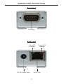
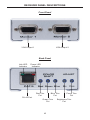
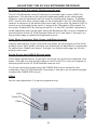
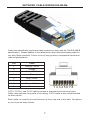
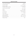
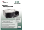
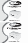
2X VGA Extender
EXT-VGA-CAT5-142
User Manual
www.gefen.com
f
ASKING FOR ASSISTANCE
Technical Support:
Telephone
Fax
(818) 772-9100
(800) 545-6900
(818) 772-9120
Technical Support Hours:
8:00 AM to 5:00 PM Monday thru Friday.
Write To:
Gefen Inc.
c/o Customer Service
20600 Nordhoff St
Chatsworth, CA 91311
www.gefen.com
[email protected]
Notice
Gefen Inc. reserves the right to make changes in the hardware, packaging and
any accompanying documentation without prior written notice.
2X VGA Extender is a trademark of Gefen Inc.
© 2008 Gefen Inc., All Rights Reserved
All trademarks are the property of their respective companies
CONTENTS
1.
Introduction
2.
Features
3.
Sender Panel Descriptions
4.
Receiver Panel Descriptions
5.
Connecting And Operating The 2X VGA Extender
6.
Adjusting The 2X VGA Extender
7.
Network Cable Wiring Diagram
8.
Specifications
9.
Warranty
INTRODUCTION
Congratulations on your purchase of the 2X VGA Extender. Your complete satisfaction is very important to us.
Gefen
Gefen delivers innovative, progressive computer and electronics add-on solutions
that harness integration, extension, distribution and conversion technologies.
Gefen’s reliable, plug-and-play products supplement cross-platform computer
systems, professional audio/video environments and HDTV systems of all sizes
with hard-working solutions that are easy to implement and simple to operate.
The Gefen 2X VGA Extender
The Gefen 2X VGA Extender allows you to extend VGA video at great distances,
up to 1,000 feet from the video source. A single industry-standard CAT5 cable
is used to carry the video signal. The 2X VGA receiver unit has two VGA video
outputs, so you can connect more than one monitor if so desired at the remote
location.
How It Works
You simply hook up the 2X VGA sender unit to your VGA video source using
the supplied 6-foot VGA mating cable, then run your CAT-5 cable to the 2xVGA
Receiver unit. At the remote end, connect your display(s) to the 2X VGA Receiver
and your video will be extended flawlessly.
OPERATION NOTES
READ THESE NOTES BEFORE INSTALLING OR
OPERATING THE 2X VGA EXTENDER
•
Resolutions up to WUXGA (1920 x 1200) are supported.
•
Maximum extension of CAT-5 or CAT-5e distance of 1000 feet (300 meters).
•
Display information (EDID) is not sent back to the source. Standard VESA
resolutions should be output by most computers without the need of an
EDID. If using a non-VESA standard resolution or if EDID is needed, an
EDID storage and relay device is necessary. Gefen recommends the use of
a DVI Detective (part# EXT-DVI-EDIDN) with two VGA to DVI adapters.
1
FEATURES
Features
•
Extends any VGA video source up to 1000 feet away
•
Uses only one CAT-5 cable for extension
•
Supports resolutions up to 1080p, 2K, and 1920 x 1200
•
Allows up to 2 VGA displays at the remote end
Package Includes
(1) VGA Extender Sender Unit
(1) VGA Extender Receiver Unit
(1) 6 foot VGA Cable (M-F)
(1) 5V External Power Supply
(1) User’s Manual
2
SENDER PANEL DESCRIPTIONS
Front Panel
VGA Input
Back Panel
Link LED
Indicator
Power LED
Indicator
RJ-45 Port
5V DC Power Input
3
RECEIVER PANEL DESCRIPTIONS
Front Panel
VGA Output 1
VGA Output 2
Back Panel
Link LED
Indicator
Power LED
Indicator
Red Trim
Pot
Blue Trim
Pot
Focus Trim
Pot
RJ-45 Port
Green Trim
Pot
4
Brightness Trim
Pot
CONNECTING AND OPERATING THE 2X VGA EXTENDER
How to Connect the 2X VGA Extender
1.
Connect the VGA source to the 2X VGA Extender sender unit using the
supplied VGA cable
2.
Connect the 2X VGA Extender sender unit and receiver unit together using a
user supplied CAT-5 or CAT-5e cable.
NOTE: When terminating cabling, please adhere to the TIA/EIA-568-B
specification. Please see page 7 for more details.
3.
Connect the displays to the 2X VGA Extender using user supplied VGA
cables.
4.
Connect the included 5V DC power supply to the 2X VGA Extender sender
unit.
5.
Power on the display first, and the source second. The LED indicators on
both the 2X VGA Extender sending and receiving units should now be lit .
The receiver unit relies on power from the sender unit. If the receiver unit’s
LED indicators are not lit, please check the CAT-5 cabling and ensure that a
proper connection has been made.
6.
If the image appears blurry or smeared, please refer to the next section for
instructions on how to adjust the video image.
ADJUSTING THE 2X VGA EXTENDER RECEIVER
The 2X VGA Extender Receiver has a number of adjustment options to achieve
optimal video quality. There are fine and coarse adjustments for focus and
brightness. There is also individual color adjustments for cable skew. Please use
the steps below to fine tune the video signal.
Trim Pot Adjustment Procedure
All adjustments in the following section are done via trim pots that require a small
flathead device. Please follow the steps below for instructions on how to adjust
the trim pots.
1.
Insert a small flathead adjustment tool into the trim pot.
2.
Turn the trim pot in a clockwise fashion until the trim pot stop turning. Do not
force the trim pot beyond this point as it will render it useless.
3.
Turn the trim pot in millimeter increments in a counter-clockwise fashion until
the desired adjustment point is reached.
4.
Remove the trim pot adjustment tool.
5
ADJUSTING THE 2X VGA EXTENDER RECEIVER
Brightness (AGC dip switch, Brightness trim pot)
The 2X VGA Extender receiver features an automatic gain control (AGC) for
brightness. This should set the optimal brightness based on the video signal.
However, manual adjustment can be done by disabling this feature. To disable
AGC, remove the silver metallic tape on the underside of the 2X VGA Extender
receiver to expose a 2 dip switch bank and a pair of trim pots. By default, AGC is
turned on as indicated by dip switch 1 being in the ON position (Dip switch 2 is
not used). Disable AGC by turning dip switch 1 to the OFF position. Adjustment
to the brightness can now be done using the Brightness (Br.) trim pot, located on
the back panel of the 2X VGA Extender receiver unit. Use steps 1 through 4 on
the previous page to adjust the brightness trim pot.
Color Skew Correction (Red, Green, and Blue trim pots)
Varying cable quality, length, and skew may offset the convergence of the three
primary colors. Red, green, and blue can individually be adjusted to compensate
for cable skew. Please use steps 1 through 4 on the previous page on the trim
pots for each color.
Focus (Focus and CABLE EQ trim pots)
If the image appears blurry or ghosted, the focus may need to be adjusted. Use
steps 1 through 4 on the previous page on the Focus (Foc.) trim pot, located on
the back panel of the 2X VGA Extender receiver unit.
The focus can be fine tuned using the CABLE EQ trim pot located on the
underside of the 2X VGA Extender. Use steps 1 through 4 on the previous page
to adjust the CABLE EQ trim pot.
Offset
Not for user adjustment. For service purposes only.
AGC
Cable EQ
Offset
6
NETWORK CABLE WIRING DIAGRAM
Gefen has specifically engineered their products to work with the TIA/EIA-568-B
specification. Please adhere to the table below when field terminating cable for
use with Gefen products. Failure to do so may produce unexpected results and
reduced performance.
Pin
Color
1
Orange / White
2
Orange
3
Green / White
4
Blue
5
Blue / White
6
Green
7
Brown / White
8
Brown
12345678
CAT-5, CAT-5e, and CAT-6 cabling comes in stranded and solid core types.
Gefen recommends using solid core cabling. CAT-6 cable is also recommended
for best results.
Each cable run must be one continuous run from one end to the other. No splices
or use of punch down blocks.
7
SPECIFICATIONS
Video Amplifier Bandwidth ....................................................................... 350 MHz
Input Video Signal .............................................................................. 1.2 Volts p-p
Input Sync Signal ........................................................................ 5 Volts p-p (TTL)
Horizontal Frequency Range ................................................................ 15-70 KHz
Vertical Frequency Range ................................................................... 30 - 170 Hz
Video In ............................................................................................... HD-15 Male
Video out ................................................................................... (2) HD-15 Female
Link Connector .............................................................................. RJ-45 Shielded
Power Supply .............................................................................................. 5V DC
Power Consumption ........................................................................ 5 Watts (max.)
Sender Dimensions ...................................................................... 1”W x 1”H x 4”D
Receiver Dimensions ................................................................... 3”W x 1”H x 4”D
Shipping Weight ............................................................................................ 3 lbs.
8