1
AOC-STG-I2
USER'S GUIDE
Rev. 1.0
Add-on Card User's Guide
The information in this User’s Manual has been carefully reviewed and is believed to be accurate.
The vendor assumes no responsibility for any inaccuracies that may be contained in this document,
makes no commitment to update or to keep current the information in this manual, or to notify any
person or organization of the updates. Please Note: For the most up-to-date version of this
manual, please see our web site at www.supermicro.com.
Super Micro Computer, Inc. ("Supermicro") reserves the right to make changes to the product
described in this manual at any time and without notice. This product, including software, if any,
and documentation may not, in whole or in part, be copied, photocopied, reproduced, translated or
reduced to any medium or machine without prior written consent.
IN NO EVENT WILL SUPERMICRO BE LIABLE FOR DIRECT, INDIRECT, SPECIAL, INCIDENTAL,
SPECULATIVE OR CONSEQUENTIAL DAMAGES ARISING FROM THE USE OR INABILITY TO
USE THIS PRODUCT OR DOCUMENTATION, EVEN IF ADVISED OF THE POSSIBILITY OF
SUCH DAMAGES. IN PARTICULAR, SUPERMICRO SHALL NOT HAVE LIABILITY FOR ANY
HARDWARE, SOFTWARE, OR DATA STORED OR USED WITH THE PRODUCT, INCLUDING THE
COSTS OF REPAIRING, REPLACING, INTEGRATING, INSTALLING OR RECOVERING SUCH
HARDWARE, SOFTWARE, OR DATA.
Any disputes arising between manufacturer and customer shall be governed by the
laws of Santa Clara County in the State of California, USA. The State of California, County of
Santa Clara shall be the exclusive venue for the resolution of any such disputes. Super Micro's
total liability for all claims will not exceed the price paid for the hardware product.
WARNING: Handling of lead solder materials used
in this product may expose you to lead, a chemical known
to the State of California to cause birth defects and other
reproductive harm.
Manual Revision 1.0
Release Date: December 7, 2007
Unless you request and receive written permission from SUPER MICRO COMPUTER, you may not
copy or otherwise reproduce/distribute any part of this document.
Information in this document is subject to change without notice. Other products and companies
referred to herein are trademarks or registered trademarks of their respective companies or mark
holders.
Copyright © 2007 by SUPER MICRO COMPUTER INC.
All rights reserved.
Printed in the United States of America
ii
Safety Information and Technical Specifications
Table of Contents
Introduction
Overview .............................................................................................................v
Product Features.................................................................................................v
Supported Operating Systems ...........................................................................vi
Required Cables ................................................................................................vi
Contacting Supermicro ...................................................................................... vii
Chapter 1 Safety Guidelines
1-1
ESD Safety Guidelines ................................................................................... 1-1
1-2
General Safety Guidelines .............................................................................. 1-1
1-3
An Important Note to Users ............................................................................ 1-2
Chapter 2 Add-on Card Components
2-1
Front Connectors and LEDs ........................................................................... 2-1
2-2
Front Connector and LED Definitions ............................................................. 2-2
3-1
Before Installation ........................................................................................... 3-1
3-2
Hardware Installation ...................................................................................... 3-1
3-3
Windows 2003/XP/2000 Installation ............................................................... 3-2
3-4
Linux Installation ............................................................................................. 3-2
Build a Binary RPM Package ........................................................................ 3-2
Manually Build the Driver ................................................................................ 3-2
iii
Add-on Card User's Guide
Notes
iv
Safety Information and Technical Specifications
Introduction
Overview
This manual is written for system integrators, PC technicians and knowledgeable
PC users who intend to integrate Supermicro's AOC-STG-I2 Add-on Card.
Product Features
The AOC-STG-I2 offers the following features:
•
High-performing, PCI-E 10Gb Ethernet connection ideally suited for demanding
enterprise applications.
•
Dual-port Intel® 82598EB with two CX4 connectors.
•
CX4-to-Optical module/cable (optional).
•
PCI-E x8 to maximize performance (PCI-E Gen 2 compatible).
•
Intel I/O Acceleration Technology (I/O AT) for improved CPU utilization.
•
x16 Virtual Machine Device queues (VMDq) for virtualized environment.
•
Direct Cache Access (DCA) to eliminate cache misses and reduce CPU load.
•
•
Tx/Rx, IP, TCP, and UDP checksum offloading (IPv4, IPv6) capabilities to increase throughput and lower processor utilization
Simple Network Management Protocol (SNMP) and Remote Network Monitoring
(RMON) statistic counters.
•
iSCSI boot.
•
Preboot eXecution Environment (PXE) support.
•
Energy-efficient design (maximum 6.5W).
•
RoHS Compliant 6/6.
v
Add-on Card User's Guide
Supported Operating Systems
The AOC-STG-I2 supports the following Operating Systems (OS):
•
Windows 2000/Windows XP/Windows 2003
•
Linux
•
VMWare ESX Server
Required Cables
The AOC-STG-I2 requires the following cables:
•
•
CX4 copper-based cable. Maximum length 15 meters.
InfiniBand 4x DDR cable (converts CX4 to optical). Maximum length 100 meters.
vi
Safety Information and Technical Specifications
Contacting Supermicro
Headquarters
Address:
Super Micro Computer, Inc.
980 Rock Ave.
San Jose, CA 95131 U.S.A.
Tel:
+1 (408) 503-8000
Fax:
+1 (408) 503-8008
Email:
[email protected] (General Information)
[email protected] (Technical Support)
Web Site:
www.supermicro.com
Europe
Address:
Super Micro Computer B.V.
Het Sterrenbeeld 28, 5215 ML
's-Hertogenbosch, The Netherlands
Tel:
+31 (0) 73-6400390
Fax:
+31 (0) 73-6416525
Email:
[email protected] (General Information)
[email protected] (Technical Support)
[email protected] (Customer Support)
Asia-Pacific
Address:
Super Micro Computer, Taiwan
4F, No. 232-1, Liancheng Rd.
Chung-Ho 235, Taipei County
Taiwan, R.O.C.
Tel:
+886-(2) 8226-3990
Fax:
+886-(2) 8226-3991
Web Site:
www.supermicro.com.tw
Technical Support:
Email:
[email protected]
Tel:
886-2-8228-1366, ext.132 or 139
vii
Safety Information and Technical Specifications
Chapter 1
Safety Guidelines
To avoid personal injury and property damage, carefully follow all the safety steps
listed below when accessing your system or handling the components.
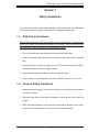
1-1
ESD Safety Guidelines
Electric Static Discharge (ESD) can damage electronic components. To prevent damage to your system, it is important to handle it very carefully. The following measures
are generally sufficient to protect your equipment from ESD.
•
•
•
Use a grounded wrist strap designed to prevent static discharge.
Touch a grounded metal object before removing a component from the antistatic
bag.
Handle the add-on card by its edges only; do not touch its components, peripheral chips, memory modules or gold contacts.
•
When handling chips or modules, avoid touching their pins.
•
Put the card and peripherals back into their antistatic bags when not in use.
1-2
•
•
•
General Safety Guidelines
Always disconnect power cables before installing or removing any components
from the computer.
Disconnect the power cable before installing or removing any cables from the
system.
Make sure that the add-on card is securely and properly installed on the motherboard to prevent damage to the system due to power shortage.
1-1
Add-on Card User's Guide
1-3
•
An Important Note to Users
All images and layouts shown in this user's guide are based upon the latest PCB
Revision available at the time of publishing. The card you have received may or
may not look exactly the same as the graphics shown in this manual.
1-2
Safety Information and Technical Specifications
Chapter 2
Add-on Card Components
2-1
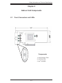
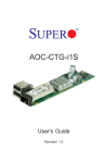
Front Connectors and LEDs
1
3
2
1
Components
1. LAN Connector Ports
2. LAN Port LEDs
3. Intel® 82598EB
2-1
Add-on Card User's Guide
2-2
Front Connector and LED Definitions
1. LAN ports
LAN ports allow the Add-on card to connect a maximum of two network cables (CX4
connectors). Each LAN port provides up to 10 gigabits per second connection speed
and require CX4 copper-based cables for maximum throughput.
The ports are designated Port 1 and Port 2.
2. LAN Port LEDs
Each LAN port has a corresponding bi-level, dual-color LED which indicates connection, activity, and connection speed (in Giga-bits/second). Review the table
below for LEDs definitions.
Color
Definition
Yellow
1Gb link speed
Blinking yellow
1Gb Activity
Green
10Gb link speed
Blinking Green
10Gb Activity
2-2
Safety Information and Technical Specifications
Chapter 3
Installation
3-1
Before Installation
Before installation, do the following
1. Power down the system.
2. Remove the power cord from the wall socket.
3. Use industry standard anti-static equipment (i.e. gloves or wrist strap) and/or
an environment that prevents accidental electrostatic discharge.
4. Familiarize yourself with the server, motherboard, and/or chassis documentation.
5. Confirm that your Operating System includes the latest updates and hotfixes.
3-2
Hardware Installation
To install the add-on card, do the following:
1. Remove the server cover and, if necessary, set aside any screws for later
use.
2. Remove the add-on card slot cover. If the case requires a screw, place the
screw aside for later use.
3. Position the add-on card in the slot directly over the connector and gently
push down on both sides of the card until it slides into the PCI connector.
4. Secure the add-on card to the chassis. If required, use the screw that you
previously removed.
5. Attach any necessary internal and external cables to the add-on card (see
page v for required cables).
6. Replace the chassis cover.
7. Plug the power cord into the wall socket and power up the system.
3-1
Add-on Card User's Guide
3-3
Windows 2003/XP/2000 Installation
Use the following instructions to install the drivers to a supported Windows Operating Systems. (For the latest systems, see page v.)
1. Run the Installation CD and when prompted click Install Drivers and Software.
2. Check I accept the terms in the license agreement.
3. Click Next.
4. Choose the appropriate Driver.
5. Click Next.
6. Click Install.
3-4
Linux Installation
To install the driver to a Linux system do the following:
Build a Binary RPM Package
1. Run ‘rpmbuild -tb <filename.tar.gz>’
2. Replace <filename.tar.gz> with the specific filename of the driver.
NOTE: For the build to work properly, the currently running kernel MUST match the
version and configuration of the installed kernel sources. If you have just recompiled
the kernel reboot the system now.
Manually Build the Driver
1. Move the base driver tar file to the directory of your choice. For example,
/home/username/ixgbe
or
/usr/local/src/ixgbe.
3-2
Safety Information and Technical Specifications
2. Untar/unzip archive:
tar zxf ixgbe-x.x.x.tar.gz
3. Change to the driver src directory:
cd ixgbe-x.x.x/src/
4. Compile the driver module:
make install
The binary will be installed as:
/lib/modules/[KERNEL_VERSION]/kernel/drivers/net/ixgbe/
ixgbe.[k]o
The install locations listed above are the default locations. They might not be correct
for certain Linux distributions. For more information, see the ldistrib.txt file included
in the driver tar.
NOTE: IXGBE_NO_LRO is a compile time flag. The user can enable it at compile
time to remove support for LRO from the driver. The flag is used by adding `CFLAGS_
EXTRA=-”DIXGBE_NO_LRO”` to the make file when it’s being compiled.
make CFLAGS_EXTRA=”-DIXGBE_NO_LRO” install
5. Load the module:
For kernel 2.6.x, use the modprobe command:
modprobe ixgbe <parameter>=<value>
For 2.6 kernels, the insmod command can be used if the full path to the driver
module is specified. For example:
insmod /lib/modules/<KERNEL VERSION>/kernel/drivers/net/ixgbe/ixgbe.ko
In addition when using 2.6 based kernels make sure that older ixgbe drivers are
removed from the kernel, before loading the new module. To do this, use:
rmmod ixgbe; modprobe ixgbe
3-3
Add-on Card User's Guide
6. Assign an IP address to the interface by entering the following, where x is the
interface number:
ifconfig ethx <IP_address> netmask <netmask>
7. Verify that the interface works. Enter the following, where <IP_address> is the
IP address for another machine on the same subnet as the interface that is being
tested:
ping <IP_address>
3-4