1
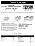
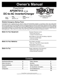
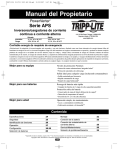
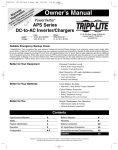
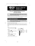
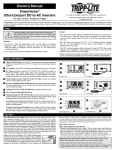
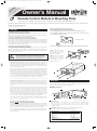
200603011--APSRM2 Owner’s Manual Update.qxd
Y :
NT ION for a Lite ty
A
T
R A ay pp ran
AR TR e tod E Tri /war
W IS lin RE om
G n F .c
RE er o a lite
t win ipp
r
gis
re e to w.t
w
c
w
an
ch uct—
d
o
pr
3/24/2006
3:22 PM
Page 1
Owner’s Manual
1111 W. 35th Street Chicago, IL 60609 USA
Customer Support: (773) 869-1234 • www.tripplite.com
Remote Control Module & Mounting Plate
for use with select PowerVerter® Inverters (PV series) or PowerVerter® Inverter/Chargers (APS, RV or EMS series)
The Remote Control Module allows you to remotely monitor and control many of the functions of select* Tripp Lite PowerVerter PV Inverters and PowerVerter
APS, RV or EMS Inverter/Chargers.
* Only those models featuring an RJ45 Remote Port.
Installation
Mounting with Included Mounting Plate (Optional)
• For PVXXXXHF Model Inverters: Install with Inverter side of plate facing out.
Connecting to an Inverter or Inverter/Charger
Connect one end of the included RJ-type cable into the RJ45 Remote Port on the front of your
PowerVerter Inverter or Inverter/Charger. Connect the other end into either of the two RJ45
Remote Ports on the bottom of the Remote Control Module.
• For PVXXXXFC Model Inverters: Install with Inverter side of plate facing out;
place included label on plate as shown.
Connecting to Additional Remote Control Modules (Optional)
HIGH
You can control a single PowerVerter Inverter or Inverter/Charger with two separate Remote
Control Modules. Connect one Remote Control Module directly to the PowerVerter as described
above. Connect either of the two RJ45 Remote Ports on the bottom of the second Remote
Control Module directly to the remaining RJ45 Remote Port on the bottom of the first Remote
Control Module using an RJ-type cable, included.
Connecting to Vehicle's Ignition Switch (Optional)
You can set the Remote Control Module to automatically perform either one of two additional
control functions (DISABLE or ENABLE) by connecting the Remote Control Module to the
vehicle’s ignition switch. These connections are optional; the Remote Control Module will
function without these connections.
WARNING! THE IGNITION SWITCH CONTROL FUNCTION IS
ONLY FOR USE WITH 12V NEGATIVE GROUND SYSTEMS.
Wiring the Ignition Switch Control Cable to your vehicle’s ignition requires a
qualified technician, who must determine the proper wiring procedure.
MEDIUM
Placement of Label
LOW
LOW
MEDIUM
HIGH
• For Inverter/Chargers (All Models): Install with Inverter/Charger side of plate facing out.
STEP 1) Using the two included
machine screws, attach the
Mounting Plate to the front of the
Remote Control Module.
STEP 2) Using the four included
sheet metal screws, install the
Mounting Plate and Remote
Control Module in the panel
opening of your vehicle.
1
5.25 in. (1
“DISABLE” Control Function: This function automatically disables (turns OFF) the AC
power output from the PowerVerter when the vehicle's ignition switch is placed in the
“Engine Run” position. This function will satisfy local codes and requirements concerning
video monitors (or TVs) that are located within a driver’s view by automatically turning
them off when the engine is started.
3.335 cm
.)
3.25 in
(8.255 cm
.)
Using the interface cable* (included with select models), connect the black lead to vehicle
ground (battery negative). Connect the red lead to the “Engine Run” terminal of the
vehicle’s ignition switch. Then, connect the interface cable’s mini-plug to either of two
Ignition Switch Control Jacks located on the side panel of the Remote Control Module: if
you are controlling a PV Inverter, insert the mini-plug into the jack labeled “J-1”; if you are
controlling an APS, RV or EMS Inverter/Charger, insert the mini-plug into the jack labeled
“J-2”. After connecting the interface cable, set the Remote Control Module's switch to
either “ON” (for PV models) or “CHRG ONLY” (for APS, RV or EMS models).
2
* The interface cable (included with select models) has a mini-plug on one end and two wire leads (one black and one red) on the other.
Using the interface cable** (included with select models), connect the black lead to vehicle
ground (battery negative). Connect the red lead to the “Accessory” terminal of the vehicle’s
ignition switch. Then, connect the interface cable’s mini-plug to either of two Ignition
Switch Control Jacks located on the side panel of the Remote Control Module: if you are
controlling a PV Inverter, insert the mini-plug into the jack labeled “J-2”; if you are
controlling an APS, RV or EMS Inverter/Charger, insert the mini-plug into the jack labeled
“J-1”. After connecting the interface cable, set the Remote Control Module’s switch to
either “ON” (for PV models) or “CHRG ONLY” (for APS, RV or EMS models).
Operation
Choose operation based on whether you connect your Remote Control Module to an Inverter
(PV series) or Inverter/Charger (APS, RV or EMS series).
INVERTER (PV series)
6
1
J1
6
* Note: a very small discharge current (approximately 18 milliamps) will still exist that should not affect starting ability, even if the
vehicle engine has not been turned on for several days. To reduce this current to zero, set the Remote Control Module’s switch to either
“OFF” (for PV models) or “AUTO” (for APS, RV or EMS models).** The interface cable (included with select models) has a mini-plug
on one end and two wire leads (one black and one red) on the other.
2
Mount the Remote Control Module in a variety of ways (under-counter, recessed, etc.)
using user-supplied hardware inserted through the Module's mounting holes/slots and into
the mounting surface.
6
3
4
5
Module shown without mounting plate
1
OFF/ON Switch:
Move this switch to the “ON” position to have your Inverter provide connected equipment
with AC power by converting DC power from an attached battery.
To prevent battery drain, leave it in the “OFF” or “INV OFF”* position when not using
connected equipment.
2
“BATTERY” LEDs: These three lights show the approximate charge of your
connected batteries. See chart below for approximate charges.
Mounting Without Included Mounting Plate (Optional)
Affix either one of the two included labels to the front panel of the Remote Control Module.
The labels identify the Module's LEDs. Choose the label marked "PV" if you are using the
Remote Control Module to operate a Tripp Lite Inverter. Choose the label market "APS" if
you are using the Remote Control Module to operate a Tripp Lite Inverter/Charger.
J2
OFF
“ENABLE” Control Function: This function automatically enables (turns ON) the AC
power output from the PowerVerter when the vehicle's ignition switch is placed in either the
“Accessory” or “Engine Run” positions. This function minimizes the risk of discharging the
vehicle battery when the vehicle is parked with the engine off for an extended period of
time.*
LEDs Illuminated
Green
Green & yellow
Yellow
Yellow & red
Red
All three lights off
Flashing red
All three lights flash slowly
All three lights flash quickly
Approximate Charge
96% - Full
81% - 95%
61% - 80%
41% - 60%
21% - 40%
1% - 20%
0% (Inverter shutdown)
Excessive discharge
Overcharge
* “OFF” when used with lable; “INV OFF” when used with mounting plate.
200603011--APSRM2 Owner’s Manual Update.qxd
Operation
3/24/2006
3:22 PM
Page 2
Operation
(continued)
“LOAD” LEDs: These three lights show the approximate load demand on your Inverter.
See chart below for approximate load levels.
3
LEDs Illuminated
Green
Green & yellow
Yellow
Yellow & red
Red
All three lights off
Flashing red
Approximate Load
0% - 20%
21% - 40%
41% - 60%
61% - 80%
81% - Full
Inverter off
Overload
RJ45 Remote Ports: Use to connect the Remote Control Module to either an Inverter or a
second Remote Control Module. See Installation section.
4
5
Ignition Switch Control Jacks: Use to connect the Remote Control Module to your
vehicle’s ignition (with cable supplied on select models only) in order to automatically
control the Inverter with the vehicle’s ignition switch. See Installation section.
6
Mounting Holes/Slots: Front panel holes can be used either to attach included Mounting
Plate or to mount Remote Control Module behind a panel. Top and side panel slots can be
used to attach Remote Control Module (without the Mounting Plate) either under or along a
variety of surfaces with user-supplied hardware.
3
“LINE” LED: This green light will turn continuously ON whenever connected equipment
is receiving utility-supplied AC power and your Inverter/Charger is set to
“AUTO/REMOTE,” meaning that it will automatically switch to battery power if AC power
becomes unavailable. The light will flash intermittently when connected equipment is
receiving utility power and your Inverter/Charger’s Operating Mode Switch is set to “CHRG
ONLY” to indicate that the Inverter/Charger’s inverter is OFF and that the Inverter/Charger
will not supply power from connected batteries.
4
“INV” LED: This yellow light will turn continuously ON whenever connected equipment is
receiving battery-supplied AC power. It will flash if the Inverter/Charger does not detect the
minimum load necessary to activate the inverter.
5
7
6
RJ45 Remote Ports: Use to connect the Remote Control Module to either an Inverter/Charger
or a second Remote Control Module. See Installation section.
7
Ignition Switch Control Jacks: Use to connect the Remote Control Module to your
vehicle’s ignition (with cable supplied on select models only) in order to automatically
control the Inverter/Charger with the vehicle’s ignition switch. See Installation section.
8
Mounting Holes/Slots: Front panel holes can be used either to attach included Mounting
Plate or to mount Remote Control Module behind a panel. Top and side panel slots can be
used to attach Remote Control Module (without the Mounting Plate) either under or along a
variety of surfaces with user-supplied hardware.
APS
1
8
J1
AUTO
J2
8
AL
SEE MANU
2
6
3
4
5
“LOAD” LED: This red light will turn continuously ON when your Inverter/Charger is
receiving utility-supplied AC power and the load is between 80% and 110% of capacity to
alert you that the inverter might not be able to support the load. The light will flash
intermittently after the Inverter/Charger's inverter shuts down due to a severe overload or
overheating.
NOTE!: To remotely reset the Inverter/Charger after a shutdown due to overload, move
the Remote Control Module’s “CONTROL” Switch to the “CHRG ONLY” or
“LINE/CHARGE ONLY”* position until the LOAD LED goes out. Remove the overload
by turning off some connected equipment. After allowing a few moments for the
Inverter/Charger to cool, switch the Remote Control Module’s “CONTROL” Switch back
to “AUTO” or “AUTO/INVERT”*.
INVERTER/CHARGER (APS, RV or EMS series)
8
(continued)
* “AUTO” and “CHRG ONLY” when used with lable; “AUTO/INVERT” and “LINE/CHARGE ONLY” when used with mounting plate.
8
Module shown without mounting plate
Limited Warranty
1
2
CONTROL Switch: Move this switch to the “AUTO” or “AUTO/INVERT”* position to
have your Inverter/Charger provide connected equipment with AC power (converted from DC
power from attached batteries) in the event of an AC power outage. Move it to the “CHRG
ONLY” or “LINE/CHARGE ONLY”* position when equipment is not in use to conserve
battery power by disabling the inverter. The “LINE” LED will flash while the switch is in this
position to remind you that battery power will not be available in the event of a blackout or
disconnection from utility/shore power. In either position, the Inverter/Charger will supply AC
power to connected equipment and charge connected batteries while AC input is present.
Tripp Lite warrants its products to be free from defects in materials and workmanship for a period of one year (domestic) or 120 days
“BATT VOLT/CHRG CURR” LEDs: These three lights will turn ON in several sequences
to show two separate operational conditions depending on the position of the CONTROL
Switch.
EXCEPT AS PROVIDED HEREIN, TRIPP LITE MAKES NO WARRANTIES, EXPRESS OR IMPLIED, INCLUDING WARRANTIES OF
If the switch is in the “AUTO” or “AUTO/INVERT”* position, the LEDs indicate the
approximate charge level and voltage of your connected battery bank and alert you to several
fault conditions. See Chart 2A for charge and voltage levels.
(export) from the date of initial purchase. Tripp Lite’s obligation under this warranty is limited to repairing or replacing (at its sole option)
any such defective products. To obtain service under this warranty you must obtain a Returned Material Authorization (RMA) number from
Tripp Lite or an authorized Tripp Lite service center. Products must be returned to Tripp Lite or an authorized Tripp Lite service center with
transportation charges prepaid and must be accompanied by a brief description of the problem encountered and proof of date and place
of purchase. This warranty does not apply to equipment which has been damaged by accident, negligence or misapplication or has been
altered or modified in any way. This warranty applies only to the original purchaser who must have properly registered the product within
10 days of purchase.
MERCHANTABILITY AND FITNESS FOR A PARTICULAR PURPOSE. Some states do not permit limitation or exclusion of implied
warranties; therefore, the aforesaid limitation(s) or exclusion(s) may not apply to the purchaser.
EXCEPT AS PROVIDED ABOVE, IN NO EVENT WILL TRIPP LITE BE LIABLE FOR DIRECT, INDIRECT, SPECIAL, INCIDENTAL OR
CONSEQUENTIAL DAMAGES ARISING OUT OF THE USE OF THIS PRODUCT, EVEN IF ADVISED OF THE POSSIBILITY OF SUCH
DAMAGE. Specifically, Tripp Lite is not liable for any costs, such as lost profits or revenue, loss of equipment, loss of use of equipment,
loss of software, loss of data, costs of substitutes, claims by third parties, or otherwise.
* “AUTO” and “CHRG ONLY” when used with lable; “AUTO/INVERT” and “LINE/CHARGE ONLY” when used with mounting plate.
WARRANTY REGISTRATION
2A
†
†
BATTERY CHARGE INDICATION (Approximate)
CONTROL SWITCH IS IN THE "AUTO" OR “AUTO/INVERT” POSITION
LEDs Illuminated
Battery Capacity (Charging/Discharging)
Green
Green & Yellow
Yellow
Yellow & Red
Red
All three lights off
Flashing red
91%–Full
81%–90%
61%–80%
41%–60%
21%–40%
1%–20%
0% (Inverter shutdown)††
Visit www.tripplite.com/warranty today to register the warranty for your new Tripp Lite product. You'll be automatically entered into a
drawing for a chance to win a FREE Tripp Lite product!*
* No purchase necessary. Void where prohibited. Some restrictions apply. See website for details.
Regulatory Compliance Identification Numbers
For the purpose of regulatory compliance certifications and identification, your Tripp Lite product has been assigned a unique series
number. The series number can be found on the product nameplate label, along with all required approval markings and information.
When requesting compliance information for this product, always refer to the series number. The series number should not be confused
with the marking name or model number of the product.
This product designed and engineered in the USA.
Charge levels listed are approximate. Actual conditions vary depending on battery condition and load.
Inverter shutdown protects battery against damage due to excessive discharge.
††
LEDs Illuminated
All three lights
flash slowly†
All three lights
flash quickly††
Fault Condition
Excessive discharge (Inverter shutdown)
Overcharge (Charger shutdown)
† Approximately ½ second on, ½ second off. See Troubleshooting section. Inverter shutdown protects battery
against damage due to excessive discharge. †† Approximately ¼ second on, ¼ second off. Charger shutdown
protects battery against damage due to overcharge. May also indicate a battery charger fault exists.
If the switch is in the “CHRG ONLY” or “LINE/CHARGE ONLY”* position, the LEDs
indicate the approximate charge rate of the Inverter/Charger. See Chart 2B for charge rates.
Note: the charge rates in the chart are expressed as percentages of the Inverter/Charger's rated
charging amps, which vary by model. Refer to the Inverter/Charger's Owner's Manual to
determine the charging amps of your specific model.
* “AUTO” and “CHRG ONLY” when used with lable; “AUTO/INVERT” and “LINE/CHARGE ONLY” when used with mounting plate.
2B
CHARGE RATE INDICATION (Approximate)
CONTROL SWITCH IS IN THE "CHRG ONLY" OR “LINE/CHARGE ONLY” POSITION
LEDs Illuminated
Charge Rate
All three lights on
Overcharge error†
Red
75% - 100%
Red & yellow
50% - 75%
Yellow
25% - 50%
Green
0% - 25%
All three lights off
0%
†
If all three lights remain on, an internal fault may exist. Turn off and disconnect the unit. Then, call Tripp Lite at
(773) 869-1234 for assistance.
1111 W. 35th Street Chicago, IL 60609 USA • Customer Support: (773) 869-1234
www.tripplite.com
Copyright © 2006 Tripp Lite. All rights reserved. PowerVerter® is a registered trademark of Tripp Lite.
The policy of Tripp Lite is one of continuous improvement. Specifications are subject
to change without notice.
200603011 93-2236