1
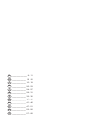
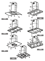
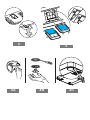
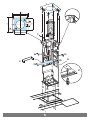
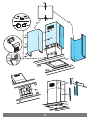
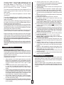
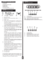
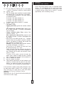
D GB F NL MONTAGE- UND GEBRAUCHSANWEISUNG INSTRUCTION ON MOUNTING AND USE PRESCRIPTIONS DE MONTAGE ET MODE DEMPLOI MONTAGEVOORSCHRIFTEN EN GEBRUIKSAANWIIZING I ISTRUZIONI DI MONTAGGIO E DUSO E MONTAJE Y MODO DE EMPLEO P INSTRUÇÕES PARA MONTAGEM E UTILIZAÇÃO RU ÈÍÑÒÐÓÊÖÈÈ ÏÎ ÓÑÒÀÍÎÂÊÅ È ÏÎËÜÇÎÂÀÍÈÞ GR ÏÄÇÃÉÅÓÿÓÕÍÁÑÌÏËÏÃÇÓÇÓÿÊÁÉÿ×ÑÇÓÇÓ PL INSTRUKCJE MONTA¯U I U¯YCIA HU SZERELÉSI ÉS HASZNÁLATI UTASÍTÁS CZ NÁVOD NA MONTÁ A POUITÍ D ______________ 8 - 11 GB _____________ 12 -15 F _____________ 16 - 19 NL _____________ 20 - 23 I _____________ 24 - 27 E _____________ 28 - 31 P _____________ 32 - 35 RU ____________ 36 - 40 GR _____________ 41 - 46 PL _____________ 47 - 51 HU _____________ 52 - 56 CZ _____________ 57 - 60 7 7 6 6 1 1 3 3 5 1A 2 2 5 4 4 7 1B 7 6 6 1 3 1 3 4 4 2 1C 5 5 7 2 1D 7 6 5 6 1 3 4 4 1 2 7 5 2 3 1F 1G 6 1 3 1H 5 2 4 g j f g f1 i g g f2 h 2 4A 3 4B 4C 3 4 4 4 4 4 273 4 244 6 6 273 190 7 14,5 5 214 6 9 7 7 8 8 7 7 2a 2a 2a 2a S 2b B 2b 12 10 11 5 10 10 10 11 14 F 15 G 15 15 15 13F 16 H 15 15 13A 16 15 15 6 18 18 18 18 17 18 18 18 18 18 18 17 M X 20 19 20 19 7 X Consult the designs in the front pages referenced in the text by alphabet letters. Closely follow the instructions set out in this manual. All responsibility, for any eventual inconveniences, damages or fires caused by not complying with the instructions in this manual, is declined. The cooker hood must be placed at a minimum distance of 50 cm from the cooking plane for electric cookers and 75cm for gas or mixed cookers. Do not tile, grout or silicone this appliance to the wall. Surface mounting only. The hood is equipped with a top air outlet B for discharge of fumes to the outside (Ducting version exhaust pipe and pipe fixing clamps not provided). Should it not be possible to discharge cooking fumes and vapour to the outside, the hood can be used in the filter version, fitting an activated carbon filter and the deflector F on the support (bracket) G, fumes and vapours are recycled through the top grille H by means of an exhaust pipe connected to the top air outlet B and the connection ring mounted on the deflector F (exhaust pipe and pipe fixing clamps not provided). The models with no suction motor only operate in ducting mode, and must be connected to an external suction device (not supplied). Expansion wall plugs are provided to secure the hood to most types of walls/ceilings. However, a qualified technician must verify suitability of the materials in accordance with the type of wall/ceiling. The wall/ ceiling must be strong enough to take the weight of the hood. Do not tile, grout or silicone this appliance to the wall. Surface mounting only. Do not fix chimney flue to furniture or fly over shelves unless the chimney flue can be easily removed, in case maintenance is ever required. Installation - Fig. 5-6-7 Preliminary information for installing the hood Assembling the deflector (Fig. 6 - 3 parts only for filter version): The three parts should be fixed with 2 screws, the deflector extension is adjustable and should correspond to the width of the chimney flue support, to which it is then fixed. During electrical connection ensure the power supply is disconnected at the domestic main switch. 1. Adjust extension of the hood support structure, as the final height of the hood depends on this, and remember that with installation completed the hood must be at least 50 cm above the cook-top for electric cookers and 75 cm for gas or mixed cookers. 2. a. Fix the two sections of the structure using 8 screws. b. If the hood is provided with extensions longer than the minimum, fit the reinforcement bracket S to the frame, using 4 screws. 3. Place the ceiling hole diagram directly above the cook-top (the center of the diagram must match the center of the cook-top and the edges must be parallel to the sides of the cook-top the side of the diagram with the wording FRONT corresponds to the control panel side). Prepare the electrical connection. 4. Drill as shown (6 holes for 6 wall plugs 4 plugs for fixture), screw the outer screws leaving a space of about 1 cm. between the screw head and the ceiling. 5. Fit an exhaust pipe inside the truss and connect it to the motor compartment connection ring (exhaust pipe and fixing brackets 12 are not supplied). 6 . Hook the frame onto the 4 screws (see step 4). CAUTION! The side of the truss with connection box corresponds to the side of the control panel with hood assembled. 7. Tighten the 4 screws. 8. Insert and tighten another 2 screws in the remaining free holes for secure fixing. 9. Carry out the electrical connection to the mains power supply, only turn on the power supply upon completion of assembly. 10. Hook the hood onto the truss, ensuring it fits properly to hook the hood onto the truss partially tighten 4 screws (see also step 12). 11. Secure the hood to the truss using two screws; this will also help center the two sections. 12. Tighten the 4 screws securing the truss to the hood. 13. For extractor versions (13A), connect the other end of the exhaust pipe to the flue. For filter versions (13F), fit deflector F to the truss and secure it to the bracket supplied using 4 screws, then connect the exhaust pipe to the connection ring located on the deflector. 14. Fit the nuts with fixing hooks supplied inside the top and bottom sections of the flues at the rectangular slots. A total of 10 nuts must be fitted. 15. Join the two top sections of the flue to cover the truss so that one of the slots on the sections is situated on the same side of the control panel and the other on the opposite side. Screw the two sections together with 4 screws (2 each side- see the plan diagram for joining the two sections). 16. Fix the top flue assembly to the truss, near the ceiling, with two screws (one each side). 17. Carry out electrical connection of control panel and bulbs. Warning! Make connections taking care to insert the connectors in the right way. 18. Join the two bottom sections of the flue covering the truss using 6 screws (3 each side, see the plan diagram for joining the two sections). 19. Insert the bottom section of the flue in its seat so that it completely covers the motor compartment and electrical connection box, then ensure it from inside the hood using two screws. 20. Apply the 2 tabs (supplied) to cover the fixing points of the bottom flue (CAUTION! THE BOTTOM FLUE TABS ARE THE NARROWER AND SHALLOWER ONES). The wider and deeper tabs are those used for the top flue, and must be cut to size. 21. Turn the mains power on again at the central electrical panel and check for correct hood operation. Electrical connection The electrical tension must correspond to the tension noted on the label placed inside the cooker hood. Connect the electrical plug, where provided, to the an easily accessible outlet in conformity with local standards in force. Where an electrical plug is not provided (for direct connection to electrical network) place a standards approved bipolar switch with an aperture distance of not less than 3mm (accessible) from the contacts. Description of the hood - Fig. 1 1 Control panel 2 Grease filter 3 Grease filter release handle 4 Halogen lamp 5 Vapour screen 6 Telescopic chimney 7 Air outlet (used for filter version only) Operation Model with button panel A Operation Model with electronic controls 2 3 4 1 1234- 5- 67- 89- 5 6 7 B C D HE D B FC GD A E 8 9 A. on/off light switch B. on/off aspiration switch and minimum power selection B+C. medium power selection aspiration switch B+D. maximum power selection aspiration switch E. operating gauge (foreseen in the model with round buttons) Motor OFF button ON button and motor speed selection button 1 - 2 - 3 1-2-.... Speed 1 LED Speed 2 LED and metal grease filter saturation LED (in this latter case, the LED will flash - See instructions on grease filter cleaning). Once the grease filters have been cleaned, press button 1 for about 3 seconds until you hear the acoustic signal (beep): the LED 4 will now stop flashing. Speed 3 LED and active carbon filter saturation LED (in this latter case, the LED will flash - See instructions on active carbon filter replacement). Once you have replaced the charcoal filter, press button 1 for about 3 seconds until you hear the acoustic signal (beep). LED 5 will now stop flashing. Warning! The active carbon filter saturation LED is not activated. In order to activate the active carbon filter saturation indicator, press buttons 2 and 7 simultaneously for 3 seconds. Initially, only LED 4 will flash, then after the 3 seconds have passed, LED 5 will also start flashing, indicating that the active carbon filter saturation control system is active. To switch off the system, re-press the same two buttons: after 3 seconds LED 5 will stop flashing and the device will be switched off. Intensive speed LED Intensive speed ON switch This speed should be used when the concentration of cooking fumes or odours is particularly strong (for example when frying, cooking fish etc.). T h e fast speed will run for about 5 minutes and then return to the speed previously set automatically (1, 2 or 3), or switch off if no speed was selected. To turn off the fast speed, before the end of the 5 minutes, press button 1 or button 2. OFF lamp button ON lamp button If the hood fails to operate correctly, briefly disconnect it from the mains power supply for almost 5 sec. by pulling out the plug. Then plug it in again and try once more before contacting the Technical Assistance Service. a a. b. c. d. e. 13 b c d e on/off light switch off aspiration switch minimum power selection aspiration switch medium power selection aspiration switch maximum power selection aspiration switch Functioning - Model with display $ % & ' ( ) Operation All cooker hood versions * Use the high suction speed in cases of concentrated kitchen vapours. It is recommended that the cooker hood suction is switched on for 5 minutes prior to cooking and to leave in operation during cooking and for another 15 minutes approximately after terminating cooking. A OFF key (Display off) /Stand-by (led lit on the display) press for a long time to select the function desired. B - Lighting, on/off. C - Timer for selected speed (visualizes the speed selected and flashing LED on the lower side of the display). This knob permits the operation of the cooker hood for a established period: 20 minutes if the speed selected is 1 15 minutes if the speed selected is 2 10 minutes if the speed selected is 3 5 minutes if the intensive speed P is selected. D - Display showing: Fan speed (1-3-P). Change grease filters (grease filter saturation indicator - F) After washing the anti-grease filter, depress knob A for about 3 seconds. The letter F will disappear from the display. Change activated carbon filters (carbon filter saturation indicator - C). After replacing the charcoal filter, depress knob A for about 3 seconds. The letter C will disappear from the display. When the led in the lower right side is on, it indicates that the cooker hood is ready for operation (standby position), the flashing LED indicates that the timer has been activated for selected speed. Attention! The active carbon filter saturation indicator is normally deactivated, to activate it: Set the hood on OFF (display off), press keys C and G contemporaneously for 3 secs. Initially, only letter F will fbe displayed, then after the 3 seconds have passed, letter C will be displayed as well, indicating that the carbon filter saturation control system is active. To switch off the system, re-press the same two buttons: letter C appear on display and after 3 seconds letter it disappear and the device will be switched off. E - Knob to decrease the speed. F - Knob to increase the speed. G - Timed intensive speed button: the hood operates at this speed for 5 minutes and than returns to the previus settings. The display will show P and a blinking dot. This function can be cancelled by pressing button A. If the hood fails to operate correctly, briefly disconnect it from the mains power supply for almost 5 sec. by pulling out the plug. Then plug it in again and try once more before contacting the Technical Assistance Service. Warning! Always press the fan off button A before disconnecting the hood from the mains supply. 14 3 . Close the lamp cover (it will snap shut). For models shown in Fig. 1E: 1. Use a small screwdriver as a lever on the borders of the lamp in order to remove the lightbulb. (fig. 4C). 2. Slide out the lightbulb to be replaced and replace with a new 12V 20W 30° Ø35 12V GU4 PHILIPS STANDARD LINE code 425409. Maintenance Prior to any maintenance operation ensure that the cooker hood is disconnected from the power supply. Cleaning: The cooker hood should be cleaned regularly internally and externally. For cleaning use a cloth moistened with denatured alcohol or neutral liquid detergents. Avoid abrasive detergents. Warning: Failure to carry out the basic standards of the cleaning of the cooker hood and replacement of the filters may cause fire risks. Therefore we recommend observing these instructions. If the lights do not work, make sure that the lamps are fitted properly into their housings before you call for technical assistance. Grease filter This must be cleaned once a month (or when the filter saturation indication system if envisaged on the model in possession indicates this necessity see previous page) using non aggressive detergents, either by hand or in the dishwasher, which must be set to a low temperature and a short cycle. When washed in a dishwasher, the grease filter may discolour slightly, but this does not affect its filtering capacity. To remove the grease filter, pull the spring release handle (f) - (Fig. 2). Caution This appliance is designed to be operated by adults. Children should not be allowed to tamper with the controls or play with the appliance. Do not use the cooker hood where the grill is not correctly fixed! The suctioned air must not be conveyed in the same channel used for fumes discharged by appliances powered by other than electricity. The environment must always be adequately aerated when the cooker hood and other appliances powered by other than electricity are used at the same time. Flambé cooking with a cooker hood is prohibited. The use of a free flame is damaging to the filters and may cause fire accidents, therefore free flame cooking must be avoided. Frying of foods must be kept under close control in order to avoid overheated oil catching fire. Carry out fumes discharging in accordance with the regulations in force by local laws for safety and technical restrictions. Charcoal filter (filter version only) It absorbs unpleasant odours caused by cooking. The charcoal filter can be washed once every two months (or when the filter saturation indication system if envisaged on the model in possession indicates this necessity see previous page) using hot water and a suitable detergent, or in a dishwasher at 65°C (if the dishwasher is used, select the full cycle function and leave dishes out). Eliminate excess water without damaging the filter, then remove the mattress located inside the plastic frame and put it in the oven for 10 minutes at 100° C to dry completely. Replace the mattress every 3 years and when the cloth is damaged. Remove the filter holder frame by turning the knobs (g) 90° that affix the chimney to the cooker hood (Fig. 3). Insert the pad (i) of activated carbon into the frame (h) and fit the whole back into its housing (j). This appliance is marked according to the European directive 2002/96/EC on Waste Electrical and Electronic Equipment (WEEE). By ensuring this product is disposed of correctly, you will help prevent potential negative consequences for the environment and human health, which could otherwise be caused by inappropriate waste handling of this product. on the product, or on the documents The symbol accompanying the product, indicates that this appliance may not be treated as household waste. Instead it shall be handed over to the applicable collection point for the recycling of electrical and electronic equipment. Disposal must be carried out in accordance with local environmental regulations for waste disposal. For more detailed information about treatment, recovery and recycling of this product, please contact your local city office, your household waste disposal service or the shop where you purchased the product. It is possible to use a traditional carbon filter, neither washable nor regenerable, to be replaced every 3 - 4 months. The filter holder frame of the carbon filter is welded together; the eventual frame supplied with the hood is not, therefore, to be used. Insert it into its housing and fix it turning the 2 plastic knobs. Replacing lamps - Fig. 4 Warning! Prior to touching the light bulbs ensure they are cooled down. For models shown in Fig. 1A: 1 . press on the lamp cover and release to open. (fig. 4A). 2. Replace the damaged light bulb. Only use halogen bulbs of 20W max (G4), making sure you do not touch them with your hands. 3. Close the lamp cover (it will snap shut). For models shown in Fig. 1B-1C-1D-1G-1H: 1. Extract the guard by levering it off with a small screwdriver or similar tool.. (fig. 4B). 2 . Replace the damaged light bulb. Only use halogen bulbs of 20W max (G4), making sure you do not touch them with your hands. 15