1
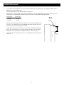
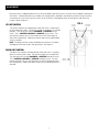
The
POWER In
PRESENTATION PRODUCTS
Instruction Book for
PRO IMAGER
DA-LITE SCREEN COMPANY, INC.
3100 North Detroit Street
Post Office Box 137
Warsaw, Indiana 46581-0137
Phone: 574-267-8101
800-622-3737
Fax: 574-267-7804
www.da-lite.com
e-mail: [email protected]
IMPORTANT SAFETY INSTRUCTIONS
When using your video equipment, basic safety precautions
should always be followed, including the following:
1. Read and understand all instructions before using.
2. Position the cord so that it will not be tripped over, pulled,
or contact hot surfaces.
3. If an extension cord is necessary, a cord with a current rating at least equal to that of the appliance should be used.
Cords rated for less amperage than the appliance may overheat.
4. To reduce the risk of electric shock, do not disassemble this
appliance. Contact an authorized service dealer when repair
work is required. Incorrect reassembly can cause electric
shock when the appliance is used subsequently.
5. The use of an accessory attachment not recommended by
the manufacturer may cause a risk of fire, electric shock, or
injury to persons.
SAVE THESE INSTRUCTIONS
1
FRAME ASSEMBLY
FIG. 1
TOOLS REQUIRED FOR ASSEMBLY
SLAT BAR
5/16" socket or wrench
Carpenters level
Tape Measure
1.
2.
Unpack frame pieces and lay them face down on
the floor. The top frame has the roller and motor
assembly attached to it. The side frames are the
two short pieces.
CHANNEL
Attach the side frame pieces to the top frame.
See figure 1. Insert the slat bar into the small
channel located on the side frame. Fasten the
frame pieces with four #10 x 3/4" hex head
screws.
#10 x 3/4" SCREWS
FIG. 2
NOTE: the top and bottom frame pieces will overlap the side frame pieces.
3.
HORIZONTAL MASK ONLY - Attach the bottom
frame with four #10 x 3/4" hex head screws.
Attach the bottom brackets with the two screws
at the back of the frame as shown in figure 2.
PULL STRAP
GUIDE
VERTICAL MASK ONLY - Attach the pull straps to
the bottom slat bar by sliding the looped end of
the pull straps over the ends of the slat bar (See
figure 2 for pull strap attachment). The bottom
roller is spring loaded and has an internal lock to
keep it from retracting during shipping. To disengage the lock pull on the slat bar to unroll the
mask but DO NOT let go of the slat bar. To lock
the roller let the mask retract slowly and the lock
will engage. The lock will only engage when the
frame is laying face down on the floor. When the
frame assembly is hanging on the wall the lock
will not engage. Insert the slat bar into the small
channel on the side frame. Fasten the bottom
frame with four #10 x 3/4" hex head screws.
Attach the bottom brackets with the two screws
at the back of the frame as shown in figure 2.
1/8" MAX.
PULL STRAP
SLAT BAR
VIEWING
SURFACE
BOTTOM
BRACKET
#10 x 3/4" SCREW
2
INSTALLATION (Continued)
1.
To install the Pro Imager over a Da-Lite Perm-Wall screen you will need to place the supplied wooden spacers
between the screen and the wall.
Da-Snap and Imager screens do not require any spacers.
2.
Refer to figure 3 for hanger bracket location. Dimension A will vary depending on the type of screen you have.
Dimension A is measured from the top of the screen frame to the top of the hanger bracket.
Screen type
Perm-Wall
Imager
Da-Snap
Dimension A
3-7/8"
3-7/8"
4-3/8"
FIG. 3
HANGER
BRACKET
Securely fasten the hanger bracket to the wall. It is recommended that you
use #10 x 1-3/4" wood screws (not supplied) and fasten into the wall stud.
Use a level to make sure the bracket is level.
To provide easy access to the limit control switches (see adjustment procedures) you will need at least 7" clearance above the top of the Pro Imager.
Hang the frame assembly on the hanger bracket as shown in figure 3.
4.
Fasten the bottom bracket to the wall with the appropriate type fastener for
your wall.
3
SCREEN
3.
A
SPACER
BLOCK
PRO IMAGER INSTALLATION
120V WIRING DIAGRAM
COMMON
WHITE
UP
BLACK
DOWN
RED
TO MOTOR
RED
ROCKER
SWITCH
UP
WHITE
BLACK
OPERATING SWITCH,
SWITCH BOX, AND
PLATE FURNISHED
WITH SCREEN. (SPDT
WITH CENTER OFF)
BLACK WITH
YELLOW
OFF
DOWN
AC COMMON
SIDE VIEW
OF SWITCH
AND BOX
AC HOT
120V. 60-HZ 2.5 MAX. AMP
THIS SWITCH CANNOT BE USED WITH LVC.
Note: A single switch cannot be used to operate more than
one screen. Contact the factory for further information.
240 VOLT WIRING DIAGRAM
FOR STANDARD WALL SWITCH:
Da-Lite offers two styles of 240 volt
wall switches for standard operation.
Please see wiring diagram included in
wall switch box included with screen.
4
IN MULTIPLE CONTROL
INSTALLATIONS THIS SWITCH
IS REPLACED BY THE LOW
VOLTAGE CONTROL, OPERATED FROM PUSH BUTTON
STATIONS.
ADJUSTMENT
Masking travel is stopped automatically in the up and down positions by limit switches that are properly adjusted at
the factory. Should it be necessary to adjust the stop positions, proceed in the following manner using a small flat
screwdriver or a 5/32" allen wrench. Access to the switches is provided by holes on the top left side of the Pro
Imager. Refer to figure 4.
FIG. 4
UP LIMIT CONTROL
UP LIMIT
CONTROL
The up limit controls the stop position when the mask is traveling up,
or unmasking the screen. Set the Pro Imager to the down, or masked
position. Turn the up limit control CLOCKWISE to DECREASE the up
travel. Turn it COUNTER-CLOCKWISE to INCREASE the up travel. Turn
the control a quarter turn at a time and then run the Pro Imager to
check the stop position. Repeat the above steps until the desired position is reached.
NOTE: The bottom of the slat bar should be no more than 1/8" above
the edge of the frame while in the up position. See figure 2.
DOWN LIMIT CONTROL
The down limit controls the stop position when the mask is traveling
down, or masking the screen. Set the Pro Imager in the up position.
Turn the down limit control CLOCKWISE to DECREASE the down travel.
Turn it COUNTER-CLOCKWISE to INCREASE the down travel. Turn the
control a quarter turn at a time and then run the Pro Imager to check
the stop position. Repeat the above steps until the desired position is
reached.
5
VIEWING
SURFACE
DOWN LIMIT
CONTROL
TROUBLESHOOTING
SYMPTOM
1. Screen will not operate or will
not go “down”.
Motor does not hum.
CAUSE
SOLUTION
(a) Blown facility fuse.
(a) Replace facility fuse.
(b) Tripped facility circuit breaker.
(b) Reset circuit breaker.
(c) No power to operating switch or
junction.
(c) Check above. Tighten all loose wire
connections. Recheck wiring. See
installation instructions.
“Down” Position
Check for power across black and white
leads.
Power at junction box.
Motor hums.
2. Screen will not move “up”.
Motor does not hum.
Motor hums.
(d) Thermal overload tripped.
(d) Let motor cool down for 15 minutes.
Try again.
(e) Defective motor, limit switch or
capacitor.
(e) Replace motor assembly.
NOTE: Motor is a sealed assembly.
(f)
(f)
Temporary binding.
With power “off“ turn roller by hand
to free binding.
(a) Blown facility fuse.
(a) Replace facility fuse.
(b) Tripped facility circuit breaker.
(b) Reset facility circuit breaker.
(c) No power to operating switch or
junction box.
(c) Check above. Tighten all loose wire
connections. See above.
Power at junction box.
“Up” Position
Check for power across red and white
leads.
(d) Thermal overload tripped.
(d) Let motor cool down for 15 minutes.
Try again.
(e) Defective motor, limit switch or
capacitor.
(e) Replace motor assembly.
NOTE: Motor is a sealed assembly.
(f)
(f)
Temporary binding.
With power “off”, turn roller by hand
to free binding.
3. Noise.
NOTE: Screen will operate with a
low-pitched hum.
(a) Grinding. Foreign object in screen
rubbing on roller or fabric.
(a) Remove.
4. Coasting.
(a) Defective brake.
(a) Replace motor assembly.
5. Roller displaced from mounting
brackets.
(a) Pin end slipped out of nylon bearing.
(a) Remove pin end mounting. Realign
motor in tube. Reattach pin end.
6. Mask hangs crooked.
(a) Screen not installed properly.
(a) Check for level and plumb.
(b) Fabric is damaged.
(b) Replace fabric.
(a) Limit switches out of adjustment.
(a) See adjustment procedures.
7. Mask does not stop at proper
position.
6
Printed in U.S.A.
82391 Rev. 7/09
7