1
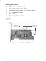
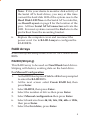
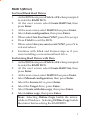
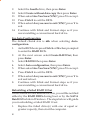
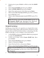
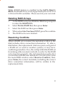
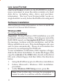
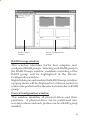
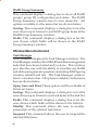
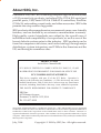
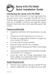
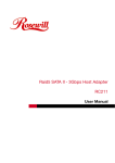
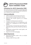
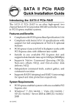
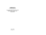
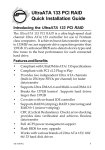
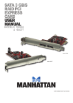
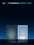
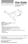
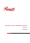
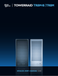
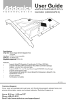
Serial ATA 4-Channel RAID
Quick Installation Guide
Introducing the Serial ATA 4-Channel RAID
The Serial ATA 4-Channel RAID is an ultra high-speed
four channel Serial ATA controller for use in Pentium
class computers. It achieves burst data transfer rates up
to 150MB/s (1.5Gb/s) and supports various brands of
hard disk drives with capacities greater that 137GB.
Features and Benefits
•
•
•
•
•
•
•
Compliant with Serial ATA Specification, revision
1.0
Compliant with PCI Specification, revision 2.2
Provides four independent channels to support up
to four Serial ATA drives
Co-exists with on-board Ultra ATA controller
Supports 32-bit wide PCI bus at 66MHz
Supports RAID 0 (striping), RAID 1 (mirroring) and
RAID 10 (mirroring+striping) RAID Arrays and
Single and JBOD modes
Lower pin count and voltage requirement, plus
better cabling over traditional Parallel ATA make
Serial ATA the controller of the future
System Requirements
•
•
Pentium® or equivalent computer with one available
PCI slot
Windows® 2000 / XP (32-/64-bit) / Server 2003
(32-/64-bit) / Vista (32-/64-bit)
04-0370B
1
Package Contents
•
•
•
•
•
•
Serial ATA 4-Channel RAID
4 Serial ATA data cables (1M)
2 Dual Connector Serial ATA power cables
2 "Y" split power cables
Driver CD
Quick Installaton Guide
Layout
Hard Disk
LED Pins
Serial ATA
Connectors
CN4
CN3
CN2
CN1
Figure 1. Serial ATA 4-Channel RAID layout
2
Hardware Installation
General instructions for installing the card are provided
below. Since the design of computer cases and
motherboards vary, refer to your computer’s reference
manual for further information, if needed.
Static electricity discharge may permanently damage
your system. Discharge any static electricity build up in
your body by touching your computer case for a few
seconds. Avoid any contact with internal parts and
handle cards only by their external edges.
1.
2.
3.
4.
5.
6.
7.
Turn OFF the power to your computer and any
other connected peripheral devices.
Unplug the power cord from the back of the
computer.
Remove your computer’s cover.
Remove the slot bracket from an available PCI slot.
To install the card, carefully align the card's bus
connector with the selected PCI slot on the
motherboard. Push the board down firmly, but
gently, until it is well seated.
Replace the slot bracket's holding screw to secure
the card.
Now go to Device Connection to connect your
Serial ATA hard disk drives.
Device Connection
It is recommended to use identical hard drives for all
RAID configurations, however, it's possible to combine
hard drives of different sizes and makes.
1.
Install your hard disk drive(s) in the chassis.
3
2.
3.
Connect the Serial ATA hard disk drive to the system
power supply using the included Dual Connector
Serial ATA power cable.
Connect one end of the Serial ATA data cable to the
hard disk drive.
Serial ATA cable
Power cable adapter
Figure 2. Hard disk drive connections
4.
Attach the other end of the Serial ATA data cable to
the Serial ATA connector on the Serial ATA
4-channel RAID.
Figure 3. Connecting the Serial ATA cable
5.
4
Follow the same instructions to connect up to four
hard drives. Device connection is now complete.
Note: If it is your desire to monitor disk activity of
the Serial ATA hard drives, you may at this time
connect the hard disk LED of the system case to the
Hard Disk LED Pins on the Serial ATA controller,
see Board Layout on page 2 for the location of the
pins. All four Serial ATA Connectors activate the
LED. For most systems connect the Red wire to the
pin farthest from the mounting bracket.
6.
Replace the computer cover and reconnect the
power cord. Go to RAID Arrays to configure the
RAID BIOS.
RAID Arrays
RAID Arrays are setup in the Serial ATA 4-Channel RAID
BIOS.
RAID 0 (Striping)
This RAID array to be used on New/Blank hard drives.
Striping will destroy existing data on the hard drive.
For Manual Configuration
1.
As the BIOS boots press Ctrl+S or F4 when prompted
to enter the RAID BIOS.
2.
At the next screen select Create RAID Set, then
press Enter.
3.
Select RAID0, then press Enter.
4.
Select the number of drives then press Enter.
5.
Select Manual configuration then press Enter.
6.
Select chunk size from 4k, 8k, 16k, 32k, 64k or 128k,
then press Enter.
7.
Select the first drive, press Enter.
5
8.
9.
10.
11.
12.
13.
Select the second drive, press Enter.
If applicable select the 3rd and 4th drives pressing
enter after each selection.
After selecting the last drive, you are asked Are You
Sure (Y/N)?, press Y to accept.
Press Ctrl+E to exit the BIOS.
When asked Are you sure to exit (Y/N)?, press Y to
exit.
Continue with Fdisk and Format steps as if you
were installing a conventional hard drive.
For Auto Configuration
The default chunk size is 64k when selecting Auto
configuration.
1.
2.
3.
4.
5.
6.
7.
8.
9.
6
As the BIOS boots press Ctrl+S or F4 when prompted
to enter the RAID BIOS.
At the next screen select Create RAID Set, then
press Enter.
Select RAID0, then press Enter.
Select the number of drives then press Enter.
Select Auto configuration, then press Enter.
When asked Are You Sure (Y/N)?, press Y to accept.
Press Ctrl+E to exit the BIOS.
When asked Are you sure to exit (Y/N)?, press Y to
exit and reboot.
Continue with Fdisk and Format steps as if you
were installing a conventional hard drive.
RAID 1 (Mirror)
For New/Blank Hard Drives
1.
As the BIOS boots press Ctrl+S or F4 when prompted
to enter the RAID BIOS.
2.
At the next screen select Create RAID Set, then
press Enter.
3.
At the next screen select RAID1 then press Enter.
4.
Select Auto configuration, then press Enter.
5.
When asked Are You Sure (Y/N)?, press Y to accept.
6.
Press Ctrl+E to exit the BIOS.
7.
When asked Are you sure to exit (Y/N)?, press Y to
exit and reboot.
8.
Continue with Fdisk and Format steps as if you
were installing a conventional hard drive.
For Existing Hard Drives with Data
1.
As the BIOS boots press Ctrl+S or F4 when prompted
to enter the RAID BIOS.
2.
At the next screen select Create RAID Set, then
press Enter.
3.
At the next screen select RAID1 then press Enter.
4.
Select Manual configuration, then press Enter.
5.
Select the Source drive, press Enter.
6.
Select the Target drive, press Enter.
7.
Select Create with data copy, then press Enter.
8.
Select online copy, then press Enter.
Note: Selecting Online Copy builds the mirror
while in Windows. Selecting Offline Copy builds
the mirror before exiting the RAID BIOS.
7
9.
10.
11.
When asked Are You Sure (Y/N)?, press Y.
Press Ctrl+E to exit the BIOS.
When asked Are you sure to exit (Y/N)?, press Y to
exit.
Note: If during restart the RAID BIOS reports an
incomplete Mirror set, disregard the message,
continue booting, and let the Mirror rebuild.
Creating a SPARE Drive
When a hard drive failure occurs in a mirror set, the autorebuild feature enables a drive designated as SPARE to
become the new member of the mirror set.
1.
During boot press Ctrl+S or F4 to enter the RAID
BIOS.
2.
Select Create RAID Set press Enter.
3.
Select SPARE DRIVE, then press Enter.
4.
Select the single hard drive then press Enter.
5.
When asked Are You Sure (Y/N)?, press Y to confirm.
6.
Press Ctrl+E to exit.
7.
When asked Are you sure to exit (Y/N)?, press Y to
exit.
The SPARE drive will not be seen by Windows, however,
it remains in the background waiting to rebuild the
mirror in the event of a hard drive failure.
Rebuilding a Failed Mirror Set
When a failure to one member occurs, you will be notified
either by the RAID BIOS during boot or by the SATA
Raid GUI while in Windows. The steps below will guide
you in rebuilding a failed mirror set.
1.
8
Replace the failed drive(s) with one of equal or
greater capacity, then start the computer.
2.
3.
4.
5.
6.
7.
8.
During boot press Ctrl+S or F4 to enter the RAID
BIOS.
Select Create RAID set then press Enter.
Select SPARE DRIVE then press Enter.
Select the replacement drive then press Enter.
When asked Are You Sure (Y/N)?, press Y to confirm.
Press Ctrl+E to exit.
When asked Are you sure to exit (Y/N)?, press Y to
exit.
Note: If during restart the RAID BIOS reports an
incomplete RAID set, disregard the message,
continue booting, and let the Mirror rebuild.
RAID 10 (Mirror+Striping)
This RAID set is used on New/Blank hard drives, do not
use existing hard drive(s) with data. To create a MirroredStriped set four hard drives are required.
For Manual Configuration
1.
As the BIOS boots press Ctrl+S or F4 when prompted
to enter the RAID BIOS.
2.
At the next screen select Create RAID Set, then
press Enter.
3.
Select RAID10 then press Enter.
4.
Select Manual configuration, then press Enter.
5.
Select chunk size from 4k, 8k, 16k, 32k, 64k or 128k,
then press Enter.
6.
Select the first drive, press Enter.
7.
Select the second drive, press Enter.
8.
Select the third drive, then press Enter.
9
9.
10.
11.
12.
13.
14.
Select the fourth drive, then press Enter.
Select Create without data copy then press Enter.
When asked Are You Sure (Y/N)?, press Y to accept.
Press Ctrl+E to exit the BIOS.
When asked Are you sure to exit (Y/N)?, press Y to
exit.
Continue with Fdisk and Format steps as if you
were installing a conventional hard drive.
For Auto Configuration
The default chunk size is 64k when selecting Auto
configuration.
1.
2.
3.
4.
5.
6.
7.
8.
As the BIOS boots press Ctrl+S or F4 when prompted
to enter the RAID BIOS.
At the next screen select Create RAID Set, then
press Enter.
Select RAID10 then press Enter.
Select Auto configuration, then press Enter.
When asked Are You Sure (Y/N)?, press Y to accept.
Press Ctrl+E to exit the BIOS.
When asked Are you sure to exit (Y/N)?, press Y to
exit and reboot.
Continue with Fdisk and Format steps as if you
were installing a conventional hard drive.
Rebuilding a Failed RAID 10 Set
When a failure to one member occurs, you will be notified
either by the RAID BIOS during boot or by the SATA
Raid GUI while in Windows. The steps below will guide
you in rebuilding a failed RAID 10 set.
1.
10
Replace the failed drive(s) with one of equal or
greater capacity, then start the computer.
2.
3.
4.
5.
6.
7.
8.
During boot press Ctrl+S or F4 to enter the RAID
BIOS.
Select Create RAID set then press Enter.
Select SPARE DRIVE then press Enter.
Select the replacement drive then press Enter.
When asked Are You Sure (Y/N)?, press Y to confirm.
Press Ctrl+E to exit.
When asked Are you sure to exit (Y/N)?, press Y to
exit.
Note: If during restart the RAID BIOS reports an
incomplete RAID set, disregard the message,
continue booting, and let the Mirror rebuild.
Single Drive Setup
Setting up a hard drive to operate as a single drive may
destroy all existing data on the hard drive, therefore, back
up any data on the hard drive before connecting it to the
RAID controller or use a blank or new hard drive.
1.
2.
3.
4.
5.
6.
As the BIOS boots press Ctrl+S or F4 when prompted
to enter the RAID BIOS.
At the next screen select Create RAID Set, then
press Enter.
Select Concatenation, then press Enter.
Select 1, then press Enter.
Select the hard drive, then press Enter.
When asked Are You Sure (Y/N)?, press Y to accept.
Note: In the RAID BIOS screen, under Logical Drive,
SiI Concatenation and the size of the logical drive
will appear.
7.
Press Ctrl+E to exit the BIOS.
11
8.
When asked Are you sure to exit (Y/N)?, press Y to
exit and reboot.
Note: The hard disk will show up as Contiguous in
the SATARAID5 GUI.
JBOD Drive Setup
This RAID Array combines the full capacity of two or
more hard drives to form one logical drive. Since this
configuration will destroy all existing data on each hard
drive, use blank or new hard drives or back up the
existing data before connecting to the raid controller.
1.
2.
3.
4.
5.
6.
As the BIOS boots press Ctrl+S or F4 when prompted
to enter the RAID BIOS.
At the next screen select Create RAID Set, then
press Enter.
Select Concatenation, then press Enter.
Select the number of drives, then press Enter.
Select each hard drive, then press Enter in succession.
When asked Are You Sure (Y/N)?, press Y to accept.
Note: In the RAID BIOS screen, under Logical Drive,
SiI Concatenation and the size of the logical drive
will appear.
7.
8.
Press Ctrl+E to exit the BIOS.
When asked Are you sure to exit (Y/N)?, press Y to
exit and reboot.
Note: When multiple drives are combined using
JBOD, each hard disk drive will appear as
Concatenated in the SATARAID5 GUI.
12
RAID5
While RAID5 feature is enabled in the SATA Raid 5
BIOS, this RAID Array is not supported by the Serial ATA
4-Channel RAID controller. Please use it at your own risk.
Deleting RAID Arrays
1.
2.
3.
4.
5.
As the BIOS boots press Ctrl+S or F4 when prompted
to enter the RAID BIOS.
Select Delete RAID Set, then press Enter.
Select the RAID set then press Enter.
When asked Are You Sure (Y/N)?, press Y to confirm.
The RAID set is now deleted.
Resolving Conflicts
When a RAID set is created, the metadata written to the
disk includes drive connection information. If, after a
disk failure, the replacement disk was previously partof
a RAID set (or used in another system), it may have
conflicting metadata. If so, this will prohibit the RAID set
from being either created or rebuilt, in order for the RAID
set to function properly, this old metadata must be first
overwritten with the new metadata. To resolve this, from
the main BIOS window select Resolve Conflicts, then
press Enter, the correct metadata, including the correct
drive connection information, will be written to the
replacement disk.
13
Low Level Format
Low Level Format is built into the RAID BIOS to make it
more convenient to erase the entire contents of a hard
disk drive, including data, drive and partition
information. The Low Level Format utility works on
single hard drives only, before the RAID set is configured.
Software Installation
This section provides information on how to install the
Serial ATA 4-channel RAID drivers.
Windows 2000
For A New Installation
Important: During Windows 2000 installation you will
be asked to restart several times. If during any restart the
RAID BIOS reports an Incomplete RAID set, disregard
the message, continue with the installation, and let the
Mirror rebuild on its own. This shouldhappen only once
and it's done automatically. Please do not interfere this
process by re-configuring the RAID sets.
A new installation of Windows 2000 requires a floppy
disk for the driver installation. To make this floppy disk,
copy the contents of the 32bit folder, found on the driver
CD, onto a blank floppy disk then follow the directions
below.
1.
2.
3.
Setup the RAID array prior to Windows installation.
Follow Microsoft's Windows 2000 installation
procedure.
At the Windows 2000 Setup screen, press F6.
Note: Prior to this step, you may be prompted to
restart in order to continue with the installation.
14
5.
6.
7.
8.
When prompted press S to specify the location of
the driver.
Insert the driver diskette, then press Enter.
Select Silicon Image Sil 3114 SoftRaid 5 Controller
for Windows 2000, then press Enter.
Press Enter to finish driver installation, then follow
the on-screen instructions to complete the
installation.
When Windows installation completes, go to SATARaid5
GUI on page 19 and install the RAID monitoring utility.
For An Existing Installation
1.
Setup the RAID array prior to driver installation and
boot up to Windows.
2.
At the Found New Hardware Wizard, click Next.
3.
Select Search for a suitable driver for my device
(recommended), then click Next.
4.
Insert the driver CD, check CD-ROM drives, uncheck
the other check boxes, then click Next.
5.
Click Next, then Finish.
6.
Repeat steps 3-5.
7.
Remove the driver CD, then restart Windows to
complete the installation.
When Windows resumes, go to SATARaid5 GUI on
page 19 and install the RAID monitoring utility.
15
Windows XP/Server 2003 (32-bit)
For A New Installation
A new installation requires a floppy disk for the driver
installation. To make this floppy disk, copy the contents
of the 32bit folder, found on the driver CD, onto a blank
floppy disk then follow the directions below.
1.
2.
3.
Setup the RAID array prior to Windows installation.
Follow Microsoft installation procedure to install
Windows accordingly.
At the Windows Setup screen, press F6 to install the
driver.
Note: Prior to this step, you may be prompted to
restart in order to continue with the installation.
4.
5.
6.
Insert the driver diskette. Press S then press Enter.
Select Silicon Image SiI 3114 SoftRaid 5 Controller
for Windows XP/Server 2003, press Enter.
Press Enter to continue and follow on-screen
instructions to complete the installation.
When Windows installation completes, go to SATARaid5
GUI on page 19 and install the RAID monitoring utility.
For An Existing Installation
1.
Install the board and boot up Windows.
2.
At the Found New Hardware Wizard.
XP (w/SP1 or earlier)/Server 2003: continue to step #3.
XP (w/SP2 or later)/Server 2003 (w/ SP1 or later): select
No, not this time, then click Next.
3.
4.
16
Insert driver CD, select Install the software
automatically (Recommended), then click Next.
Click Next, then click Finish.
5.
Remove the driver CD, shutdown Windows, and
setup your RAID array.
When Windows resumes, go to SATARaid5 GUI on
page 19 and install the RAID monitoring utility.
Windows XP/Server 2003 (64-bit)
For A New Installation
A new installation requires a floppy disk for the driver
installation. To make this floppy disk, copy the contents
of the 64bit folder, found on the driver CD, onto a blank
floppy disk then follow the directions below.
1.
2.
3.
Setup the RAID array prior to Windows installation.
Follow Microsoft procedure to install Windows
accordingly.
At the Windows Setup screen, press F6 to continue.
Note: Prior to this step, you may be prompted to
restart in order to continue with the installation.
4.
5.
6.
Insert the driver diskette. Press S then press Enter.
Select Silicon Image SiI... Controller (64-bit
Extended) and press Enter.
Press Enter to continue and follow on-screen
instructions to complete the installation.
When Windows installation completes, go to SATARaid5
GUI on page 19 and install the RAID monitoring utility.
For An Existing Installation
1.
Install the board and boot up Windows.
2.
At the Found New Hardware Wizard:
For XP (w/SP1 or earlier)/Server 2003: go to step #3.
For XP (w/SP2 or later)/Server 2003 (w/ SP1 or later):
select No, not this time, then click Next.
17
3.
4.
Insert the driver CD, select Install the software
automatically (Recommended), then click Next.
Click Finish, remove the driver CD, shutdown
Windows, and setup your RAID array.
When Windows resumes, go to SATARaid5 GUI on
page 19 and install the RAID monitoring utility.
To Verify 2000/XP/Server 2003 Installation
1.
2.
Right click My Computer, click Manage, click
Device Manager.
Double click SCSI and RAID controllers, and Silicon
Image SiI 3114 SoftRaid 5 Controller should be
displayed.
Windows Vista™ (32-/ 64-bit)
For A New Installation
1.
Setup the RAID array prior to Windows installation.
2.
Follow Windows installation procedure.
3.
At Where do you want to install Windows?, click
Load Drivers.
4.
Insert the driver CD, click Browse.
5.
Double click your CD-ROM drive,
For 32-bit Windows Vista: click OK.
For 64-bit Windows Vista: select 64bit, then click OK.
6.
Select Silicon Image SiI..., then click Next.
7.
Follow the on-screen instructions to complete
Windows Vista operating system installation.
When Windows installation completes, go to SATARaid5
GUI on page 19 and install the RAID monitoring utility.
18
For An Existing Installation
1.
2.
3.
4.
5.
Install the board and boot up Windows.
At the Found New Hardware window, click Locate
and install the driver automatically (recommended).
Insert the driver CD, click Continue.
Click Next, then click Close.
Remove the driver CD, shutdown Windows, and
setup your RAID array.
When Windows resumes, go to SATARaid5 GUI on
page 19 and install the RAID monitoring utility.
To Verify Windows Vista Installation
1.
2.
Right click Computer, click Manage, click Continue,
select Device Manager.
Double click Storage controllers, and Silicon Image
SiI 3114 SoftRaid5 Controller should be displayed.
SATARaid5 GUI
The SATARaid5 GUI provides the user an easy way to
monitor your RAID set.
SATARaid5 GUI Installation
Important: Windows 2000 SP4 or later is required for
installation.
1.
2.
Insert the driver installation CD.
At the Windows desktop click Start:
For 2000: Click Run, type D:\32bitgui.msi, then
click OK. (Change D: to match your CD-ROM drive
letter)
19
3.
For Windows XP/Server 2003
For 32-bit: Click Run, type D:\32bitgui.msi, then
click OK. (Change D: to match your CD-ROM drive
letter)
For 64-bit: Click Run, type D:\64bitgui.msi, then
click OK. (Change D: to match your CD-ROM drive
letter)
For Windows Vista
For 32-bit: In Start Search box, type D:\32bitgui.msi,
then press Enter. (Change D: to match your CDROM drive letter)
For 64-bit: In Start Search box, type D:\64bitgui.msi,
then press Enter. (Change D: to match your CDROM drive letter)
Follow the on-screen instructions to complete the
installation.
SATARaid5 GUI Overview
The installation program configures the SATARaid5 GUI
to automatically start when Windows is started. If the
GUI does not automatically start or is closed by the user,
choose the SATARaid5 program from the start menu to
launch the program. Upon launching the GUI, the main
window should appear similar to the next few pages.
20
RAID Groups
window
Device Configuration
window
RAID Groups window
This window identifies SATA host adapters and
configured RAID groups. Selecting each RAID group in
the RAID Groups window, members consisting of the
RAID group will be highlighted in the Device
Configuration window.
Right clicking on each node in the RAID Groups window,
a popup menu will be displayed to let the user select an
action to be performed for the selected controller or RAID
group.
Device Configuration window
This window identifies all physical drives and their
partitions. A physical drive can be partitioned into
several portions and each portion can be a RAID group
member.
21
SATARAID 5 Configuration Menu
SATARAID5 configuration menu includes customization
of the settings for Log File, Popup and Advanced Options.
By clicking on File, then Configuration, the user may
customize the settings for Log File, Popup and Advanced
Options tabs.
Log File
The log file is used to store event information received
from all the RAID drivers. The log file can be viewed with
any text viewer (such as Notepad) or with the Event Log
window of SATARAID5 GUI. Use the Log File tab to
enable/disable the log file, set where the log file should
be stored and the name of the file as well.
22
Popup
The popup window is a visual notification that an event
has occurred. The popup window can be disabled or set
to popup for only certain event levels.
The different levels are:
Informational - The popup window will be displayed
for the following events:
- Informational
- Warnings
- Errors
Warning - The popup window will be displayed for the
following events:
- Warnings
- Errors
Errors - The popup window will be displayed for the
following events:
- Errors
Disabled - No popup will occur
Advanced Options
The advanced options tab is used to control advanced
features of the RAID driver. By default, all advanced
options are disabled.
Legacy (Bootable) Support: When this feature is selected,
Legacy Support menu will be available in the menu bar.
The Legacy Support menu includes a list of menu items
to support RAID functions for legacy RAID groups.
Delete Member Support: When this feature is selected,
Delete Member menu item will be available under the
Device menu. The Delete Member menu item allows the
user to delete a member from RAID 1 group.
23
Advanced RAID Features: When this feature is selected
and the user selects to create RAID group, if the RAID
group to be created is fault tolerant group (RAID1), the
user will be able to select Improper Shutdown Policy in
the Create RAID Group dialog box. The Advanced RAID
Features are not supported for Legacy RAID groups.
Resources Info Support: When this feature is selected,
Resources menu item will be available under the Window
menu. This feature is for debugging purpose only.
Device Menu Command
Create Spare and Delete Spare
This command displays a dialog box to let the user create
or delete a spare drive.
Delete Member
This command displays a dialog box to let the user
choose RAID groups' members to delete. Since RAID 0 is
not fault-tolerant, RAID 0 members will not be shown in
the list.
Delete Orphan
An orphan device segment is part of a RAID group that
cannot access another device segment within the same
RAID group. When a member of a RAID group fails (such
as a loss of power or a complete hard disk failure), it
becomes an orphan. This command displays the Delete
Orphan Segment window to show all orphan segments
and allows the user to delete selected orphan segments.
Make Pass-Thru
Removes any Metadata on the drive so it will function as
an ordinary hard disk drive.
24
Device Summary
This command displays the Segment Summary window
to show all physical devices' segments.
RAID Group Menu Command
Create RAID Group
This command displays a dialog box to let user create a
RAID group, the user needs to specify the following
parameters:
RAID Group Label: Provides a name for the RAID group.
RAID Group: Select a group ID from the available ID list.
Configuration: Striped: for RAID 0; Mirrored: for RAID 1;
Contiguous: for non-RAID single drive; Concatenated: for
JBOD (requires at least 2 hard drives)
Capacity: Select from a list of RAID group sizes. Selecting
MAX will create the largest RAID set possible with the
drives selected.
Chunk Size: Select one size from the available list. This
setting is for RAID 0 (Stripe) set only.
Rebuild Priority: Select from the available list. RAID 0
and virtual disk do not require this. 10 is the highest level
of rebuild priority which means that rebuild times will be
faster but will take more CPU resources to rebuild.
Devices: Select RAID member devices from the available
device segment list.
Rebuild RAID Group
This command displays a dialog box to let the user
choose a replacement segment to rebuild a non-fault
tolerant RAID group.
Delete RAID Group
Lets the user choose RAID group(s) to delete.
25
RAID Group Summary
This command displays a dialog box to show all RAID
groups' group ID, configuration and status. The RAID
Group Summary window has it's own menu bar. All
options available via the menu bar are shown below.
Sorting: This command displays a dialog box to let the
user choose up to 3 items to sort RAID group items in the
RAID Group Summary window.
Fields: This command displays a dialog box to let the
user choose which fields will be shown in the RAID
Group Summary window.
Window Menu Command
Task Manager
This command displays the Task Manager window. The
Task Manager window list all RAID and disk management
tasks that have been started and/or done. This window
provides the user with the ability to schedule any RAID
and disk management operations including RAID group
creation, rebuild and test. The Task Manager window
has it's own menu bar. All options available via the menu
bar are shown below.
Open, Save and Print: These options will be available in
future revisions.
Sorting: This command displays a dialog box to let the
user choose up to 3 items to sort task items in the task list.
Fields: This command displays a dialog box to let the
user choose which fields will be shown in the task list.
Modify: This command allows the user to modify
parameters of the selected task items.
Suspend: This command allows the user to suspend the
selected task items.
26
Resume: This command allows the user to resume the
suspended task items.
Cancel: This command allows the user to cancel the
selected task items.
Delete: This command displays a dialog box to let the
user delete the selected task items.
Event Log
This command displays the Event Log window. The
Event Log window displays SATA device-related events
that occur while SATARAID5 GUI is running. The Event
Log window has it's own menu bar. All options available
via the menu bar are shown below.
Sorting: This command displays a dialog box to the the
user choose up to 3 items to sort event items in the event
log.
Fields: This command displays a dialog box to let the
user choose which fields will be shown in the event log.
Resources
This command displays the Resources Information
window. This feature is for debugging purpose only.
Legacy Support Menu Command
Create Legacy RAID Group
This command displays a dialog box to let the user create
legacy (bootable) RAID groups. This item is disabled if
new RAID groups exist. The parameters are discussed
below.
RAID Group: Selects a group ID from the available list.
Configuration: Striped: for RAID 0; Mirrored: for RAID 1;
Contiguous: for single drive; Concatenated: for JBOD
(requires at least 2 hard drives)
27
Capacity: Select from a list of RAID group sizes.
Chunk Size: Select one value from the available list.
Rebuild Priority: Select from the available list. RAID 0
and virtual disk do not require this. 10 is the highest level
of rebuild priority which means that rebuild times will be
faster but will take more CPU resources to rebuild.
Devices: Select RAID member devices from the available
device segment list.
Rebuild Legacy RAID Group
This command displays a dialog box to let the user
choose a replacement segment to rebuild a non-fault
tolerant legacy RAID group.
Delete Legacy RAID Group
This command displays a dialog box to let the user
choose legacy RAID groups to delete. This item is
disabled if no legacy RAID group exists.
Convert Legacy RAID Group
This command displays a dialog box to let the user
choose legacy RAID groups to convert to new RAID
groups of the same RAID type. This item is disabled if no
legacy RAID group exists.
Create/Delete/Convert Legacy Spare
These commands display a dialog box to let the user
configure a legacy spare.
28
Blank Page
29
Blank Page
30
Technical Support and Warranty
QUESTIONS? SIIG’s Online Support has answers! Simply visit our
web site at www.siig.com and click Support. Our online support
database is updated daily with new drivers and solutions. Answers
to your questions could be just a few clicks away. You can also submit
questions online and a technical support analysts will promptly
respond.
SIIG offers a lifetime manufacturer warranty with this product. Please
see our web site for more warranty details. If you encounter any
problems with this product, please follow the procedures below.
A) If it is within the store's return policy period, please return the
product to the store where you purchased from.
B) If your purchase has passed the store's return policy period, please
follow these steps to have the product repaired or replaced.
Step 1: Submit your RMA request.
Go to www.siig.com, click Support, then RMA to submit a
request to SIIG RMA. If the product is determined to be
defective, an RMA number will be issued.
Step 2: After obtaining an RMA number, ship the product.
• Properly pack the product for shipping. All software, cable(s)
and any other accessories that came with the original package
must be included.
• Clearly write your RMA number on the top of the returned
package. SIIG will refuse to accept any shipping package, and
will not be responsible for a product returned without an
RMA number posted on the outside of the shipping carton.
• You are responsible for the cost of shipping. Ship the product
to the following address:
SIIG, Inc.
6078 Stewart Avenue
Fremont, CA 94538-3152, USA
RMA #:
• SIIG will ship the repaired or replaced product via Ground
in the U.S. and International Economy outside of the U.S. at
no cost to the customer.
31
About SIIG, Inc.
Founded in 1985, SIIG, Inc. is a leading computer upgrade manufacturer
of I/O connectivity products, including PCIe, PCI & ISA serial and
parallel ports, USB, Serial ATA & UltraATA controllers, FireWire
(1394a/b), networking, sound cards, and other accessories. SIIG is the
premier one-stop source of upgrades.
SIIG products offer comprehensive user manuals, many user-friendly
features, and are backed by an extensive manufacturer warranty.
High-quality control standards are evident by the overall ease of
installation and compatibility of our products, as well as one of the
lowest defective return rates in the industry. SIIG products can be
found in computer retail stores, mail order catalogs, through major
distributors, system integrators, and VARs in the Americas and the
UK, and through e-commerce sites.
PRODUCT NAME
Serial ATA 4-Channel RAID
FCC RULES: TESTED TO COMPLY WITH FCC PART 15, CLASS
B OPERATING ENVIRONMENT: FOR HOME OR OFFICE USE
FCC COMPLIANCE STATEMENT:
This device complies with part 15 of the FCC Rules. Operation is
subject to the following two conditions: (1) This device may not cause
harmful interference, and (2) this device must accept any interference
received, including interference that may cause undesired operation.
THE PARTY RESPONSIBLE FOR PRODUCT COMPLIANCE
SIIG, Inc.
6078 Stewart Avenue
Fremont, CA 94538-3152, USA
Ph: 510-657-8688
Serial ATA 4-Channel RAID is a trademark of SIIG, Inc. SIIG and the SIIG logo are registered
trademarks of SIIG, Inc. Microsoft, Windows and Windows Vista are either registered trademarks or
trademarks of Microsoft Corporation in the United States and/or other countries. Pentium is a
registered trademark of Intel Corporation. Mac and Mac OS are registered trademarks of Apple
computer. Other names used in this publication are for identification only and may be trademarks of
their respective companies.
July, 2008
Copyright © 2008 by SIIG, Inc. All rights reserved.