1
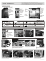
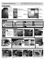
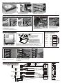
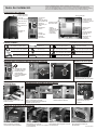
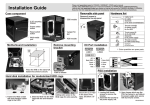
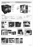
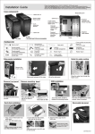
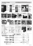
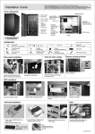
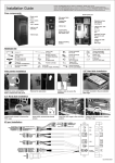
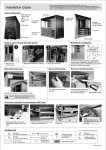
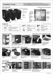
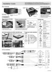
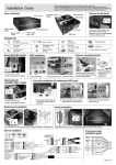
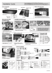
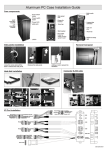
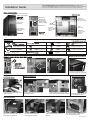
Please visit www.lian-li.com for FRANCE / GERMANY / SPAIN user's manual
Veuillez visiter www.lian-li.com pour le manuel d’installation en FRANÇAIS/ALLEMAND/ESPAGNOL.
Visite el sitio Web www.lian-li.com para obtener el manual del usuario en FRANCÉS ALEMÁN Y ESPAÑOL
Besuchen Sie bitte www.lian-li.com für die französische/ deutsche/ spanische Gebrauchsanleitung
Installation Guide
Power switch button
Reset switch button
120mm fan
Rubberized
grommets for
liquid cooling
system’s tubing
5.25" bezels
5.25" to 3.5"
convertor
120mm fan
Patented
tool-less 5.25”
device mounting
Upper
HDD cage
Front
HDD cage
Patented
tool-less PCI
add-on card
holder
Two 140mm
blue LED fans
with filter
Patented
tool-less PSU
mounting
bracket
Hardware list
(16)
Bracket(1)
for power supply mounting
Mounting bracket
for SSI CEB/EEB M/B
(8)
Thumb screw(42)
for HDD
Thumb screw(1)
for work with stand-off
(2)
Box(1)
for spare parts
Mounting bracket
Rubber ring(42)
for HDD
Shorter vision thumb screw(9)
for mother board mount
(5)
for PSU mounting
Longer vision thumb screw(3)
for mother board mount
Hex wrench for M/B(1)
stand-off
Remove the front panel
Pull the front panel toward
yourself to lease the front panel
Remove the
mounting bezel
ODD installation
Press the right and left side of the
bezel to remove.
Press plastic handle to release the
mounting bracket.
Accessing fan filter
Push the ODD into the 5.25” rack,
close the bracket to secare the ODD
Press the handle to release
the washable air filter.
PSU installation
Place the PSU on the stand, and
push again the rear panel.
Place the PSU bracket into
according slot as shown.
Lock the PSU bracket to secure
the PSU.
* For transportation, please place
screw to secure the PSU
C50.A70F0.01E-1
Hard disk installation for upper HDD cage
1. Install the screws to the HDD with
anti-vibration rubber rings.
2. Insert the HDD to the HDD cage.
3. Adding extra screw to secure.
Hard disk installation for the front HDD cage
1. Install the screws to the HDD with
anti-vibration rubber rings.
2. Slide the HDD into the front
HDD cage
Cable management note
* Remove clamp, use
tweezers to release the
cable clamp
3. Close the gate to secure the
HDD.
Use cable clamp to tidy up the cables.
Front panel cable installation
guide
!
Note: For area where hard to
reach use the long
thumb screw
!
!
for SSI CEB/EEB
The oval hole on M/B tray
designed for special server
boards, please use nut to
hold the copper bolt in place.
GROUND WHITE
POWER SW
PWR
GRAY
GROUND WHITE RESET SW
BLUE
Reset
WHITE
PLEDPOWER
NC
LED
PLED+ GREEN
IDE_LED- WHITE H.D.D LED
IDE_LED+ ORANGE
Speaker
Secure the stand-off bolts on the M/B tray which match with the
M/B fix points,place the M/B on the copper bolt, fasten with the
thumb screws to secure.
+5V
BLACK
NC
NC
RED
SPEAKER
PCI Add-on card installation
1
2
Open the aluminum latch to
remove the PCI slot bracket.
Push the card into the PCI slot,
close the aluminum latch to secure
the card.
9
7 Black(GND)
5 Green
3 White
1 Red
KEY10
Black(GND) 8
Green 6
White 4
Red 2
9
7 Black(GND)
5 Green
3 White
1 Red
1
3
5
7
9
2 Red(MIC)
4 Brown(MIC-PWE)
6 Yellow(R-OUT)
8
10 Blue(L-OUT)
EAR
MIC
USB
KEY 10
Black(GND) 8
Green 6
White 4
Red 2
Black(AGND)
NC
Yellow(R-RET)
KEY
Blue(L-RET)
USB
USB
9 Green(SENSE2 RETUR)
7 KEY
5 Orange(SENSE1 RETUR)
3 Black(PRESENCE)
1 Black(GND)
HD AUDIO
AC'97
Blue(PORT2 L) 10
Black(SENSE SEND) 8
Yellow(PORT2 R) 6
Brown(PORT1 R) 4
Red(PORT1 L) 2
Finish.
USB
9
7
5
3
1
Black(GND)
White(+12V)
Red(TPB-)
Black(VG)
Orange(TPA-)
1394
IEEE1394
Black(KEY) 10
White(+12V) 8
Green(TPB+) 6
Black(VG) 4
Blue(TPA+) 2
E-SATA
Connector
SATA Cable
C50.A70F0.01E-2
Please visit www.lian-li.com for FRANCE / GERMANY / SPAIN user's manual
Veuillez visiter www.lian-li.com pour le manuel d’installation en FRANÇAIS/ALLEMAND/ESPAGNOL.
Visite el sitio Web www.lian-li.com para obtener el manual del usuario en FRANCÉS ALEMÁN Y ESPAÑOL
Besuchen Sie bitte www.lian-li.com für die französische/ deutsche/ spanische Gebrauchsanleitung
Guide d'installation
Composants du boîtier
DEL de courant
DEL du lecteur
de disque dur
Bouton de courant
Bouton de
réinitialisation
Panneau de 5,25"
Port Multimédia
Ventilateur
120 mm
Guides revêtus
de caoutchouc
pour le tubage
du circuit de
refroidissement
par liquide
convertisseur 5,25
pouces vers 3,5
pouces
Ventilateur
120 mm
Deux ventilateurs
de 140mm avec
filtre
Plateau
PSU amovible
Dispositif de
montage du
périphérique
5,25" sans
outil breveté
Boîtier du
lecteur de
disque dur
avant
Boîtier
du lecteur
de disque
dur
supérieur
Support
de carte PCI
breveté
additionnel
à montage
sans outil
Support de
montage sans
outil breveté
du PSU
Liste du matériel
Vis (16) pour fixer le lecteur
et la carte mère
Mounting bracket
for SSI CEB/EEB M/B
Thumb screw(1)
Box(1)
for spare parts
(8)
Thumb screw(42)
for HDD
for work with stand-off
(2)
Bracket(1)
for power supply mounting
Mounting bracket
Rubber ring(42)
for HDD
Shorter vision thumb screw(9)
for mother board mount
(5)
for PSU mounting
Longer vision thumb screw(3)
for mother board mount
Hex wrench for M/B(1)
stand-off
Guide pour ouvrir les panneaux latéraux droite et gauche
Remove the front panel
1. Enlevez les quatre
vis à serrage à main
2. Faites glisser le
panneau vers
l'arrière du boîtier.
3. Soulevez le panneau
latéral
Remove the
mounting bezel
Press the right and left side of the
bezel to remove.
Pull the front panel toward
yourself to lease the front panel
ODD installation
Accessing fan filter
Appuyez sur la poignée en plastique pour
libérer le support de montage.
Poussez l'ODD dans le rack de 5,25"
Fermez le support pour maintenir
l'ODD en place.
Appuyez sur la poignée pour
libérer le filtre à air lavable.
PSU installation
Place the PSU on the stand, and
push again the rear panel.
Place the PSU bracket into
according slot as shown.
Lock the PSU bracket to secure
the PSU.
* For transportation, please place
screw to secure the PSU
C50.A70F0.01F-1
Installation du disque dur pour le boîtier supérieur du lecteur de disque dur
1. Mettez en place les vis avec les
rondelles anti-vibration en
caoutchouc, sur le lecteur de
disque dur.
2. Insérez le lecteur de disque dur
dans le boîtier
3. Ajout d'une vis supplémentaire
pour le maintien.
Installation du disque dur pour le boîtier avant du lecteur de
disque dur
1. Mettez en place les vis avec les
3. Ajout d'une vis supplémentaire
rondelles anti-vibration en caoutchouc,
pour le maintien.
sur le lecteur de disque dur.
2. Insérez le lecteur de disque dur
dans le boîtier
Remarque concernant la gestion des câbles
Utilisez la pince à câble pour serrer les
câbles.
Installation de la carte mère
* Enlevez la pince à câble,
utilisez des brucelles pour
libérer la pince à câble.
Guide d'installation du
câble du panneau avant
!
Remarque: Pour les endroits
difficiles d'accès, utilisez la vis
longue à serrage à main
!
!
Pour SSI CEB/EEB
Le trou ovale sur le plateau de la
carte mère est conçu pour des
plaques de serveurs spéciales,
veuillez utiliser l'écrou pour
maintenir le boulon en cuivre en place.
TERRE
COURANT
BLANC
GRIS
TERRE
Réinitialiser
BLANC RÉINITIALISER SW
BLEU
PLEDPLED+
BLANC
DEL de COURANT
NC
VERT
IDE_LEDIDE_LED+
BLANC DEL de disque dur
ORANGE
HAUT-PARLEUR
Fixez les boutons de la douille à sertir sur le plateau de la carte mère, de
façon à correspondre aux points de fixation de la carte mère. Positionnez
la carte mère sur le bouton en cuivre, puis serrez avec les vis à serrage à
main pour maintenir le tout.
+5V
NOIR
NC
NC
ROUGE
COURANT SW
HAUT-PARLEUR
PCI Add-on card installation
1
2
Open the aluminum latch to
remove the PCI slot bracket.
Push the card into the PCI slot,
close the aluminum latch to secure
the card.
Finish.
Installation de port d'E/S
C50.A70F0.01F-2
Please visit www.lian-li.com for FRANCE / GERMANY / SPAIN user's manual
Veuillez visiter www.lian-li.com pour le manuel d’installation en FRANÇAIS/ALLEMAND/ESPAGNOL.
Visite el sitio Web www.lian-li.com para obtener el manual del usuario en FRANCÉS ALEMÁN Y ESPAÑOL
Besuchen Sie bitte www.lian-li.com für die französische/ deutsche/ spanische Gebrauchsanleitung
Installationsanleitung
Composants du boîtier
Betriebs-LED
Festplatten-LED
Multimedia-Anschluss
Stromschalter
120mm-Lüfter
Reset-Schalter
Gummidurchgangstüllen
für Rohrleitungen des Oberer
Flüssigkühlsystems
Festplattenkäfig
5,25Laufwerkfachblende
5,25 auf 3,5 Zoll
Adapter
Patentierte
werkzeugfreie
5,25-ZollGerätebefestigung
120mm-Lüfter
Vorderer
Festplattenkäfig
Patentierter
werkzeugfreier
PCI-Kartenhalter
Zwei 140 mmLüfter mit Filter
Patentierte
werkzeugfreie
Netzteilhalterung
Herausnehmbare
Netzteilhalterung
Hardware-Liste
Übrige Teile gelten als Ersatzteile.
Schraube (16) zum Fixieren
von Laufwerk und Motherboard
Summer (1)
Rändelschraube (42)
für die Festplatte
Schraube (8)
für Befestigungshalterung
Montierrahmen (1) für SSI
CEB/EEB-Motherboard
Rändelschraube (1)
Gummiring für die
Festplatte (42 Stück)
Nahansicht der Rändelschraube (9)
für Motherboard-Befestigung
Karton (1) für Ersatzteile
Mutter (3) für Arbeit mit
Abstandhalter
Schraube (5)
für Netzteilbefestigung
Weitansicht der Rändelschraube (3)
für Motherboard-Befestigung
Haltewinkel zum Befestigen
des Netzteils (1 Stück)
Inbusschlüssel
für Abstandhalter des Motherboards (1)
Kabelbinder (2)
Öffnen der linken und rechten Abdeckplatte
Remove the front panel
1. Entfernen Sie die vier
Rändelschrauben
2. Schieben Sie die Platte
in Richtung
Gehäuserückseite.
3. Heben Sie die seitliche
Abdeckplatte an.
Remove the
mounting bezel
Press the right and left side of the
bezel to remove.
Pull the front panel toward
yourself to lease the front panel
Installation optischer Laufwerke
Drücken Sie die Kunststoffklinke
und machen das Befestigungsteil auf.
Schieben Sie das optische Laufwerk
in das 5,25-Zoll-Rack hinein
Accessing fan filter
Schließen Sie die Halterung, um
das optische Laufwerk zu sichern.
Drücken Sie auf den Griff,
um den waschbaren Luftfilter
freizugeben.
Netzteilinstallation
Stellen Sie das Netzteil auf den
Halter und drücken noch einmal die
hintere Abdeckplatte.
Legen Sie den Netzteilhalter wie
abgebildet in den vorgesehenen
Platz ein.
Befestigen Sie den PSU-Halter, um
das Netzteil zu sichern.
* Sichern Sie vor einem Transport das
Netzteil mit Schrauben
C50.A70F0.01G-1
Einbauen einer Festplatte in den oberen Festplattenkäfig
1. Verschrauben Sie die Festplatte
mit Gummischwingringen.
2. Schieben Sie die Festplatte in
den Festplattenkäfig hinein
3. Fügen Sie zur Befestigung eine
zusätzliche Schraube hinzu.
Einbauen einer Festplatte in den vorderen Festplattenkäfig
1. Ziehen Sie die Schrauben mit
Gummischwingringen an der
Festplatte fest.
2. Schieben Sie die Festplatte in
den vorderen Festplattenkäfig hinein.
Hinweis zur Kabelanordnung
3. Schließen Sie die Sperre, um
die Festplatte zu sichern.
* Verwenden Sie eine Pinzette,
um die Kabelklammer zu
lösen und abzunehmen.
Verwenden Sie die Kabelklammer, um
die Kabel anzuordnen.
Installationsanleitung für
das Fronttafelkabel
Installation der Hauptplatine
!
Hinweis: Verwenden Sie die
lange Rändelschraube für
schwer erreichbare Stellen
!
!
Für SSI CEB/EEB
Ovales Loch auf Motherboard
-Halterung für spezielle Server
-Boards; Kupferschraube mit
Mutter fixieren.
Befestigen Sie die Abstandshalterschrauben an der Motherboard-Halterung in
Übereinstimmung mit den Motherboard-Fixierpunkten, setzen Sie das
Motherboard auf die Kupferschraube auf, befestigen Sie mit Rändelschrauben.
ERDE
STROM
WEISS
GRAU
Stromschalter
ERDE
Zurückstellen
WEISS
BLAU
Rückstellschalter
PLED-
Betriebs-LED
PLED+
WEISS
NC
GRÜN
IDE_LEDIDE_LED+
WEISS
ORANGE
Festplatten-LED
Lautsprecher
SCHWARZ
NC
NC
ROT
LAUTSPRECHER
+5V
Installation einer PCI-Zusatzkarte
1
2
Stecken Sie die Karte in den PCISteckplatz hinein und schließen Sie
den Aluminiumriegel, um die Karte
zu befestigen.
Öffnen Sie den Aluminiumriegel,
um den PCI-Steckplatzhalter zu
entfernen.
Grün (SENSE2 RETUR)
SCHLÜSSEL
Orange (SENSE1 RETUR)
Schwarz (PRESENCE)
Schwarz (ERDE)
SCHLÜSSEL
Schwarz (ERDE)
Grün
Weiß
Rot
10
8
6
4
2
9
7 Schwarz (ERDE)
5 Grün
3 Weiß
1 Rot
SCHLÜSSEL 10
Schwarz (ERDE) 8
Grün 6
Weiß 4
Rot 2
9
7 Schwarz(ERDE)
5 Grün
3 Weiß
1 Rot
HD AUDIO
9
7
5
3
1
1
3
5
7
9
2 Rot (MIC)
4 Braun (MIC-PWE)
6 Gelb (R-OUT)
8
10 Blau (L-OUT)
EAR
MIC
USB
10
8
6
4
2
Schwarz (AGND)
NC
Gelb (R-RET)
SCHLÜSSEL
Blau (L-RET)
USB
USB
Blau (PORT2L)
Schwarz (SENSE SEND)
Gelb (PORT2 R)
Braun (PORT1 R)
Rot (PORT1 L)
AC'97
Installation des E/A-Anschlusses
Fertig.
USB
10
8
6
4
2
9
7
5
3
1
Schwarz (ERDE)
Weiß(+12V)
Rot(TPB-)
Schwarz(VG)
Orange(TPA-)
1394
IEEE1394
Schwarz (KEY)
Weiß (+12 V)
Grün (TPB+)
Schwarz (VG)
Blau (TPA+)
E-SATA
Anschlussstecker
SATA-Kabel
C50.A70F0.01G-2
Please visit www.lian-li.com for FRANCE / GERMANY / SPAIN user's manual
Veuillez visiter www.lian-li.com pour le manuel d’installation en FRANÇAIS/ALLEMAND/ESPAGNOL.
Visite el sitio Web www.lian-li.com para obtener el manual del usuario en FRANCÉS ALEMÁN Y ESPAÑOL
Besuchen Sie bitte www.lian-li.com für die französische/ deutsche/ spanische Gebrauchsanleitung
Guía de instalación
Componentes del gabinete
LED de encendido
LED de disco duro
Botón de
encendido/apagado
Botón de reinicio
Marco de 5,25”
Convertidor 5,25”
a 3,5”
Puerto multimedia
Ventilador de
120 mm
Montaje patentado
de dispositivos de
5,25” que no requiere
herramientas
Anillos de plástico
para la tubería del Cubierta superior
sistema de
para discos duros
refrigeración por
líquido
Ventilador de
120 mm
Ventilador de
140 mm
Bandeja
extraíble de la
fuente de
alimentación
Cubierta frontal
para discos
duros
Soporte
patentado de
tarjetas PCI de
expansión que
no requiere
herramientas
Lista de hardware
Soporte patentado
de montaje de la
fuente de
alimentación que
no requiere
herramientas
Las cantidades extra son piezas de recambio.
Tornillo (16) para sujetar
las unidades y la placa madre
Zumbador (1)
Tornillo mariposa (42)
para los discos duros
Tornillo (8) para sujetar el
soporte de montaje
Soporte de montaje (1)
para la placa madre SSI CEB/EEB
Thumb screw(1)
Anillo de goma (42)
para los discos duros
Tornillo mariposa corto (9)
para el montaje de la placa madre
Tornillo (5) para el montaje
de la fuente de alimentación
Tornillo mariposa largo (3)
para el montaje de la placa madre
Caja (1) de repuestos
Tuerca (3) para los pernos
Soporte (1) para el montaje
de la fuente de alimentación
Abrazadera de cables (2)
para los sujetar los cables
Llave hexagonal (1) para los
pernos de la placa madre
Guía para abrir los paneles laterales izquierdo y derecho
Remove the front panel
1. Extraiga los cuatro
tornillos mariposa.
2. Deslice el panel
hacia la parte
trasera del gabinete.
3. Levante el panel
lateral.
Pull the front panel toward
yourself to lease the front panel
Remove the
mounting bezel
Instalación de la unidad de discos ópticos
Accessing fan filter
Press the right and left side of the
bezel to remove.
Presione la perilla de plástico para
liberar el soporte de montaje.
Empuje la unidad de discos ópticos
hacia el soporte de 5,25”.
Presione la lengüeta para
liberar el filtro de aire
lavable.
Cierre el soporte para asegurar la
unidad de discos ópticos.
Instalación de la fuente de alimentación
Coloque la fuente de alimentación
sobre el soporte y presione
nuevamente el panel posterior.
Coloque el soporte de la fuente de
Bloquee el soporte de la fuente de
* Para el transporte, utilice los tornillos
alimentación en la ranura
alimentación para asegurar la fuente para asegurar la fuente de
correspondiente, tal como se muestra de alimentación.
alimentación.
en la ilustración.
C50.A70F0.00G-1
Instalación del disco duro en la cubierta superior para discos duros
2. Inserte el disco duro en
la cubierta para discos duros.
1. Coloque en el disco duro los
tornillos para el disco duro junto
con los anillos de goma
antivibración.
3. Agregue tornillos adicionales
para asegurar.
Instalación del disco duro en la cubierta frontal para discos
duros
Nota sobre la administración de cables
3. Agregue tornillos adicionales
para asegurar.
1. Coloque en el disco duro los
tornillos para el disco duro junto
con los anillos de goma
antivibración.
2. Inserte el disco duro en
la cubierta para discos duros.
* Extraiga la abrazadera y
utilice una pinza para liberar
la abrazadera para cables.
Utilice la abrazadera de cables para
ordenar los cables.
Instalación de la placa madre
Guía de instalación del
cable del panel frontal
!
Nota: Para un área de difícil
acceso, utilice el tornillo
mariposa largo.
!
!
Para SSI CEB/EEB
El orificio oval de la bandeja de la
placa madre está diseñado para
placas de servidor especiales.
Por favor, use la tuerca para sujetar
el perno de cobre en su sitio.
Fije los tornillos del soporte a la bandeja de la placa madre con los puntos
de fijación de la misma. Coloque la placa madre sobre el tornillo de cobre
y apriete los tornillos mariposa para fijarla.
TIERRA
ALIMENTACIÓN
BLANCO
GRIS
ALIMENTACIÓN
SW
TIERRA
Reinicio
BLANCO
AZUL
REINICIO SW
PLED-
LED ALIMENTACIÓN
PLED+
BLANCO
SC
VERDEN
IDE_LEDIDE_LED+
BLANCO
NARANJA
LED DISCO DURO
Altavoz
NEGRO
SC
SC
ROJO
Altavoz
+5V
Instalación de la tarjeta de expansión PCI
1
2
Abra el pestillo de aluminio para
extraer el soporte de la ranura PCI.
Empuje la tarjeta hacia la ranura
PCI y cierre el pestillo de aluminio
para asegurar la tarjeta.
Verde (SENSE2 RETUR)
BOTÓN
Naranja (SENSE1 RETUR)
Negro (PRESENCE)
Negro (TIERRA)
BOTÓN
Negro (GND)
Verde
Blanco
Rojo
10
8
6
4
2
9
7 Negro (GND)
5 Verde
3 Blanco
1 Rojo
BOTÓN10
Negro (GND) 8
Verde 6
Blanco 4
Rojo 2
9
7 Negro (GND)
5 Verde
Blanco
3 Rojo
1
HD AUDIO
9
7
5
3
1
2 Rojo (MIC)
4 Marrón (MIC-PWE)
6 Amarillo (R-OUT)
8
10 Azul (L-OUT)
AUR
MIC
USB
10
8
6
4
2
Negro (AGND) 1
S/Color 3
Amarillo (R-RET) 5
BOTÓN 7
Azul (L-RET) 9
USB
USB
Azul (PORT2 LI)
Negro (SENSE SEND)
Amarillo (PORT2 R)
Marrón (PORT1 R)
Rojo (PORT1 R)
AC'97
Instalación de Puerto de Entrada/Salida
Fin.
USB
9
7
5
3
1
Negro (GND)
Blanco (+12V)
Rojo (TPB-)
Negro (VG)
Naranja (TPA-)
1394
IEEE1394
Negro (KEY) 10
Blanco (+12V) 8
Verde (TPB+) 6
Negro (VG) 4
Azul (TPA+) 2
Conector
E-SATA
Cable SATA
C50.A70F0.00G-2