1
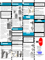
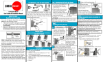
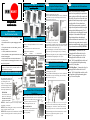
Mounting Options
OPTION II:
Before you begin, decide which mounting option and ball shaft are
appropriate for your speaker
speaker..
For Speakers That Require a Mounting
Plate to AccessThreaded Inserts
•
You must affix the mounting plate to the ball shaft before
attaching the mounting plate to the speaker:
• Pick up the ball shaft and mounting plate. Insert the threaded end
of the ball shaft into the top of the mounting plate until it butts up
against the bottom of the jam nut.
Fig. D
20.0 Speaker Mount
Installation Instructions
Before You Start
Read This Section Carefully
Tools Required
To use the 20.0 Speaker Mount Kit, your speaker must meet ONE of
You will need at least these tools for the installation
the following criteria:
•
5/32”
hex wrench (supplied)
• This mount is ONLY for speakers weighing up to 20lbs
•
Drill
bits:
¼” (for drywall installation) or 5/16” (for wood and
(9 kg).
masonry
surfaces)
• Your speaker must have one of the following means of
• 916”(11mm) open wrench or small crescent wrench
securing the mount:
• Phillips screwdriver, medium size
• A factory installed 3/8”-16 threaded insert
• Hammer
• An electric drill
• Factory installed, correctly spaced threaded inserts for use • Wire cutters
with our mounting plate
• Sturdy wood frame that can be safely drilled into and
securely attached to our mounting plate with the #14 course
thread screws provided.
CAUTION: If you have any questions or concerns regarding the
mounting of your speaker, contact a professional installer or the
speaker manufacturer as necessary.
KIT COMPONENTS AND THEIR USE
The Clamp Assembly
The clamp assembly consists of the
clamp plate and jaw and attaches to
your mounting surface (wall,
ceiling, etc). The clamp assembly
provides the clamping action that
surrounds the ball and locks in the
chosen angle of adjustment (fig. A)
The Ball Shaft
The ball shaft attaches to the
speaker in the following ways.
•
Fig. C
•
Pick up the extra jam nut. Position it so
that the circular part of the nut faces the
end of the ball shaft protruding from the bottom of the mounting plate.
Thread the nut onto the shaft a few turns only—until the top of the
nut is even with the end of the ball shaft. (Fig. C)
• Place the mounting plate on a flat surface and pull up on the ball
shaft. Screw the top jam nut down against the top of the mounting
plate.
• Attach the mounting plate to the speaker by placing the slotted holes
over the threaded insertsand tightening the screws. (Fig. D)
• Using the 9/16” open end wrench or small crescent wrench, tighten
the jam nut securely against the top of the mounting plate.
OPTION III:
For Wood Speakers with NO Threaded Inserts
•
You must affix the mounting plate to the ball shaft before attaching
the mounting plate to the speaker:
• Pick up the ball shaft and mounting plate. Insert the threaded end
of the ball shaft into the top of the mounting plate until it butts up
against the bottom of the jam nut.
OPTION I:
For Speakers With a 3/8”-16 Factory Installed
Threaded Insert
Insert the ball shaft and rotate it several turns until it is fully
threaded into the threaded female insert on the speaker. When you
Determine which format is
Fig. A
“hit bottom” back out the ball shaft one quarter turn (Fig. B).
needed for your speaker:
Fig. B
• Using the 9/16” open wrench or crescent
OPTION I— threads directly into the 3/8”-16 factory installed
wrench, firmly tighten the jam nut, but
threaded insert on the speaker
DO NOT OVER-TIGHTEN.
OPTION II– when mounting plate is necessary to access threaded
• When the ball shaft resists moderate rotational
inserts, the ball shaft attaches to the plate
force and forms a solid joint with the
OPTION III– wood speakers with no threaded inserts, the ball shaft speaker, stop tightening.
attaches to the mounting plate which is attached to speaker with
screws.
Fig. E
• Pick up the extra jam nut. Position it so that the circular part of
the nut faces the end of the ball shaft protruding from the bottom
of the mounting plate. Thread the nut onto the shaft a few turns
only—until the top of the nut is even with the end of the ball shaft.
• Place the mounting plate on a flat surface and pull up on the ball
shaft. Screw the top jam nut down against the top of the
mounting plate. (Fig. E)
OPTION III:
For Wood Speakers with NO Threaded Inserts
NOTE: When no threaded inserts for mounting
purposes have been provided by the speaker manufacturer, a speaker can still be safely mounted on the
wall or ceiling. But you have to be sure that it is put
together with materials strong enough to support its
own weight with the #14 course thread screws
provided. Most compact speakers are made well
enough and use adequate materials thick enough for
mounting with an OmniMount assembly. The #14
screws should not be used in Masonite®, thin panel
wood or plastic. Such materials will likely require
different fastening hardware and methods and
possible reinforcement to be mounted safely. If your
evaluation raises any questions about the speaker’s
construction or material strength, contact your dealer
or the speaker manufacturer and ASK QUESTIONS.
• 20.0 Wall Mount— To mount on a wall, the
mounting plate will be affixed to the back of the
speaker. If you are mounting on a side wall, the
mounting plate will be affixed to the side of the
speaker. The 20.0 straight ball shaft can also be used
for a ceiling application by affixing the mounting
plate to the top of the speaker.
• 20.0 Ceiling Mount— To mount to the ceiling, the
mounting plate will be affixed to the back of the
speaker. The 20.0 bent ball shaft can also be used for
a wall application by affixing the mounting plate to
the top or bottom of the speaker.
OPTION IV:
For Wood Speakers with NO Threaded Inserts
• Place the speaker on a scratch-proof surface. Be careful to
protect any exposed components from damage. Position the
mounting plate at the chosen location on the speaker. Using the
mounting plate as a template, with a pencil, mark the outline
of the two slots on the surface of the speaker.
STEP 3:
STEP 2:
ATT
ACHING CLAMP ASSEMBL
TTACHING
ASSEMBLYY
POSITIONING CLAMP ASSEMBL
ASSEMBLYY
• Insert the two anchors fully until the flange is flush against the
mounting surface (Fig. J & K).
• Position the clamp assembly over
the anchors.
• Insert and tighten the #12 coarse
thread screws (provided). (Fig L).
Use a Phillips screwdriver or a
Phillips bit in a battery powered
drive tool (Fig. M).
Fig. M
Ceiling or Floor Mounting
The Wall Mount Ball Shaft may also be used
to mount a speaker from the ceiling. For
installation placement, see Fig. I-2.
CAUTION: Be careful not to drill or screw into a speaker
where you could possibly damage internal components.
If there’s a question about this, check with your dealer or
the manufacturer, or you may choose to carefully remove
the driver and check inside the speaker enclosure
yourself.
•
STEP 4:
The clamp assembly should be positioned so
that the clamp plate (with the OmniMount
logo) faces in the same direction as the front
of the speaker you are mounting. The jaw
and the tension screw will face in the
opposite direction (towards the wall) (fig O).
Position the clamp assembly onto the wall,
ceiling or floor at the mounting location you
have selected.
Remove the mounting plate from
the speaker where you had been using
it as a template. Insert the 3/32” drill Fig. F
bit (provided) so that ½” sticks out
of the end of your drill.
•
Position the drill bit ¼” down from
the far end of the slot but centered in
the middle of the slot.
• Drill the pilot hole straight down
into speaker. Repeat the procedure
for the second slot location. (Fig. F).
• Place mounting plate onto the speaker,
insert the #14 screws and tighten until the Fig. G
screws are firmly seated against the top
of the mounting plate.
Do not overtighten! (Fig. G).
ATT
ACHING CLAMP ASSEMBL
TTACHING
ASSEMBLYY
Using the clamp plate as a template, mark the two holes with a pencil.
Remove the clamp plate before drilling into your mounting surface.
CAUTION: It may be necessary to check that the surface preparation and the fasteners will not interfere with electrical wiring,
plumbing, etc., behind the mounting surface (wall, ceiling, or floor).
Using the 7/16 open wrench or small
crescent wrench, tighten the jam nut
securely against the top of the mounting
plate (Fig. H).
Your OmniMount Speaker Mount is designed to be
mounted on a variety of wall and ceiling constructions.
Please follow all safety precautions listed here before
installing the Clamp and Jaw Assembly.
Fig. H
POSITIONING CLAMP ASSEMBL
ASSEMBLYY
Wall Mounting
Fig. I-2
STEP 3:
•
STEP 2:
JOINING THE BALL SHAFT
AND CLAMP ASSEMBL
ASSEMBLYY
CAUTION: Drilling holes into masonry or concrete material requires
the use of a carbide tipped 5/16” (8mm) diameter masonry drill and/or
hammer drill. Always wear eye protection.
Mounting Onto Solid Wood or Masonry
• Insert a 5/16” (8mm) diameter drill bit (not
provided). Set depth of
Position the clamp plate vertically the OmniMount Logo should be
drill at a minimum 2 1/2” (63.5mm) protruding from the end of your
facing toward the ceiling, the tension screw head faces towards the
drill.
floor (Fig. I).
•
Fig. I
Center the drill on the marked hole locations and carefully
drill the two holes to the minimum 2 ½” (63.5mm) depth.
Fig. J
Fig. K
Fig. L
• Check that the clamp assembly is open
enough to accept the ball. Get the 5/32”
(4 mm) hex wrench. Now lift the speaker
into position and “pop” the ball into the
clamp assembly. Set your chosen angle of
adjustment.
• While supporting the speaker, insert
the long end of the hex key and turn the
hex tension screw clock-wise to take up
the slack in the clamp assembly, but do
not fully tighten. (The ball should be
properly seated, and the speaker should
still move easily). (Fig. N).
Caution: Tightest is not always the best! Over tightening
fasteners can weaken the installation. Make sure the
connection is extremely solid and then stop tightening.
•
If the speaker angle must be changed, do not attempt to move
the speaker without first loosening the tension screw. Reposition, then tighten the tension screw further until the
speaker is held firmly in place.
• If rotational adjustment of the mounted speaker is required,
the jam nut must first be loosened, the speaker rotated, and the
jam nut tightened again. Use the 7/16” (11mm) open wrench or
a small adjustable crescent wrench for this procedure.
Caution: If the speaker loses its position, do not attempt to
move the speaker without first loosening the tension screw.
Reposition, then tighten the tension screw further until
the speaker is held firmly in place.
CONGRA
TULA
TIONS!
CONGRATULA
TULATIONS!
YOUR INST
ALLA
TION IS NOW COMPLETE.
INSTALLA
ALLATION
Fig. N
ADJUSTING THE POSITION OF THE SPEAKER AND TIGHTENING
THE CLAMP ASSEMBL
ASSEMBLYY
•
Orient and hold the speaker in its final fixed position.
CAUTION: The weight of the speaker must be fully supported
throughout the entire tightening process. Do not allow the ball
shaft to rest upon or push against the clamp assembly. Two
installers may be needed for this; one to support the speaker while
the other tightens the clamp assembly.
Note: The following is made in lieu of all warranties expressed
or implied. The Manufacturer’s only obligation shall be to
replace parts of this product proved to be defective within two
years of the date of purchase. We are aware that this mounting
assembly may be used for purposes and in ways other than those
for which it had been designed and manufactured. The Manufacturer, Distributor, Retail and their respective agents cannot be
held responsible or liable for injuries or property damage—
direct, indirect, or consequential—arising out of the use, or
inability to use this product safely and properly.
Note: Every effort has been made to provide accurate and errorfree assembly and installation information. Omnimount Systems
disclaims liability for any difficulties arising from the interpretation of information contained in these instructions.
•
Insert the hex key into the tension screw head
and tighten (Fig. O)
• Pick up the vice grip pliers, regular pliers,
or small crescents wrench and use one of these
Fig. O
tools to assist in tightening the tension screw.
Tighten in ½ turn increments until the speaker is
firmly held in place.
•
NOTE: To hold the speaker in position and
prevent any slippage, the clamp assembly must
get a good “bite” into the ball and form a
SOLID joint. The clamp assembly needs to be
tightened enough to lock and hold the speaker
FIRMLY at the chosen angle. When that point
is reached, no further tightening is necessary.
Omnimount Systems, Inc.
8201 South 48th Street
Phoenix, AZ 85044-5355
Voice: 480-829-8000
Fax: 480-756-9000
Email: [email protected]
Web: www.omnimount.com
Copyright 2002, Omnimount Systems, Inc. All rights reserved. OmniMount products are covered
by patents issued and/or pending. “OmniMount” is a registered trademark of Omnimount Systems, Inc.
OmniMount products are manufactured in the USA. Printed In the USA.
20.0 speaker mount kit Rev 03/02