1
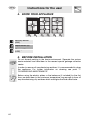
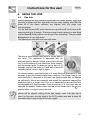
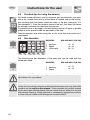
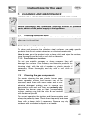
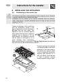
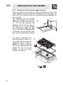
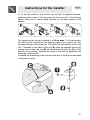
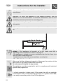
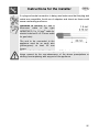
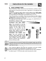
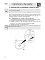
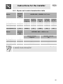
Contents
1. INSTRUCTIONS FOR USE ........................................................ 23
2. INSTRUCTIONS FOR DISPOSAL – OUR ENVIRONMENTAL
CARE .......................................................................................... 24
3. SAFETY INSTRUCTIONS .......................................................... 25
4. KNOW YOUR APPLIANCE ........................................................ 26
5. BEFORE INSTALLATION........................................................... 26
6. USING THE HOB........................................................................ 27
7. CLEANING AND MAINTENANCE.............................................. 29
8. INSTALLING THE APPLIANCE.................................................. 30
9. GAS CONNECTION ................................................................... 36
10. ADAPTATION TO DIFFERENT TYPES OF GAS ......................38
11. FINAL OPERATIONS FOR GAS APPLIANCES ........................ 40
INSTRUCTIONS FOR THE USER: these contain user advice,
description of the commands and the correct procedures for
cleaning and maintenance of the appliance.
INSTRUCTIONS FOR THE INSTALLER: these instructions are
intended for the qualified technician who must perform the installation, put it into operation and test the appliance.
22
Precautions for use
1. INSTRUCTIONS FOR USE
THIS MANUAL IS AN INTEGRAL PART OF THE APPLIANCE. IT MUST BE KEPT
IN ITS ENTIRETY AND IN AN ACCESSIBLE PLACE FOR THE WHOLE
WORKING LIFE OF THE HOB.
WE URGE YOU TO READ THIS MANUAL AND ALL THE INFORMATION IT
CONTAINS CAREFULLY BEFORE USING THE APPLIANCE.
INSTALLATION MUST BE CARRIED OUT BY QUALIFIED PERSONNEL IN
ACCORDANCE WITH THE REGULATIONS IN FORCE. THIS APPLIANCE IS
INTENDED FOR DOMESTIC USES AND CONFORMS TO THE EEC
DIRECTIVES CURRENTLY IN FORCE. THE APPLIANCE HAS BEEN BUILT TO
CARRY OUT THE FOLLOWING FUNCTIONS: COOKING AND HEATING-UP OF
FOOD; ALL OTHER USES ARE CONSIDERED IMPROPER.
THE MANUFACTURER DECLINES ALL RESPONSIBILITY FOR IMPROPER
USE.
DO NOT USE THIS APPLIANCE FOR HEATING ROOMS.
DO NOT DISCARD PACKING IN THE HOME ENVIRONMENT. SEPARATE THE
VARIOUS WASTE MATERIALS AND TAKE THEM TO THE NEAREST SPECIAL
GARBAGE COLLECTION CENTRE.
WHEN DISPOSING OF THE APPLIANCE IT MUST BE TAKEN TO A SPECIAL
GARBAGE COLLECTION CENTRE.
DO NOT OBSTRUCT VENTILATION OPENINGS AND HEAT DISPERSAL SLITS.
THE IDENTIFICATION PLATE WITH THE TECHNICAL DATA, SERIAL NUMBER
AND MARK IS IN A VISIBLE POSITION UNDER THE CASING.
THE PLATE MUST NOT BE REMOVED.
23
Instructions for disposal
2. INSTRUCTIONS FOR DISPOSAL
ENVIRONMENTAL CARE
–
OUR
Our product's packing is made of non-polluting materials, therefore
compatible with the environment and recyclable. Please help by disposing
of the packing correctly. Find the addresses of collection, recycling and
disposal centres from your retailer or from the competent local
organisations.
Do not throw the packing or any part of it away. They can constitute a
suffocation hazard for children, especially the plastic bags.
Your old appliance also needs to be disposed of correctly.
Important: hand over your appliance to the local agency authorised for
the collection of household appliances no longer in use. Correct disposal
means intelligent recycling of valuable materials.
It is also necessary to cut the electric power cord and remove it along with
the plug.
24
Safety instructions
3. SAFETY INSTRUCTIONS
REFER TO THE INSTALLATION INSTRUCTIONS FOR THE SAFETY
REGULATIONS FOR ELECTRIC OR GAS APPLIANCES AND VENTILATION
FUNCTIONS.
IN YOUR INTERESTS AND FOR YOUR SAFETY IT HAS BEEN ESTABLISHED
BY LAW THAT THE INSTALLATION AND SERVICING OF ALL ELECTRICAL
APPLIANCES IS TO BE CARRIED OUT BY QUALIFIED PERSONNEL IN
ACCORDANCE WITH THE REGULATIONS IN FORCE.
OUR REGULAR INSTALLERS GUARANTEE A SATISFACTORY JOB.
GAS OR ELECTRIC APPLIANCES MUST ALWAYS BE DISCONNECTED BY
SUITABLY SKILLED PEOPLE.
THE PLUG TO BE CONNECTED TO THE POWER CORD AND ITS SOCKET
MUST BE OF THE SAME TYPE AND CONFORM TO THE REGULATIONS IN
FORCE.
THE SOCKET MUST BE ACCESSIBLE AFTER THE APPLIANCE IS BUILT IN.
NEVER UNPLUG BY PULLING ON THE CABLE.
IT IS OBLIGATORY FOR ALL ELECTRICAL SYSTEMS TO BE GROUNDED
ACCORDING TO THE METHODS REQUIRED BY SAFETY RULES.
IMMEDIATELY AFTER INSTALLATION CARRY OUT A BRIEF INSPECTION TEST,
FOLLOWING THE INSTRUCTIONS BELOW. SHOULD THE APPLIANCE NOT
FUNCTION, DISCONNECT IT FROM THE ELECTRICITY SUPPLY AND CALL
THE NEAREST TECHNICAL ASSISTANCE CENTRE.
NEVER ATTEMPT TO REPAIR THE APPLIANCE.
THE APPLIANCE BECOMES VERY HOT DURING USE. SUITABLE HEAT-PROOF
GLOVES SHOULD BE WORN FOR ALL OPERATIONS.
THE APPLIANCE IS DESIGNED FOR USE BY ADULTS. KEEP CHILDREN AT A
SAFE DISTANCE AND NEVER ALLOW THEM TO PLAY WITH IT.
ALWAYS CHECK THAT THE CONTROL KNOBS ARE IN THE 0 (OFF) POSITION
WHEN YOU FINISH USING THE APPLIANCE.
The manufacturer declines all responsibility for damage to persons or
things caused by the non-observance of the above prescriptions or
deriving from tampering with any part of the appliance or by the use of
non-original spares.
25
Instructions for the user
4. KNOW YOUR APPLIANCE
Auxiliary Burner
(AUX)
Rapid Burner (R)
Ultra-rapid Burner
(URP)
5. BEFORE INSTALLATION
Do not discard packing in the home environment. Separate the various
waste materials and take them to the nearest special garbage collection
centre.
In order to remove all manufacturing residues, it is recommended to clean
the appliance. For further information on cleaning see point "7.
CLEANING AND MAINTENANCE".
Before using the electric plates or the barbecue (if included) for the first
time, pre-heat them to the maximum temperature long enough to burn off
any manufacturing oily residues which could give the food a bad taste.
26
Instructions for the user
6. USING THE HOB
6.1
Gas hob
Before lighting the hob burners check that the flame diffuser rings are
correctly in place with their respective burner caps, making sure that the
holes A in the flame diffusers are aligned with the plugs and
thermocouples.
For the dual burner UR2, place the burner caps G and F on the burner D,
ensuring that they fit snugly. The burner must then be placed on and fitted
into the base B (taking care to use the pin C as reference). The pan stand
B supplied is for use with woks.
The special pan stand H is for use with woks.
The burner controlled by each knob is shown next to
the knob. The appliance is equipped with an
electrical ignition device. Simply press the knob and
turn it anti-clockwise to the maximum flame symbol,
until the burner lights. If it does not light in the first 15
seconds, position the knob on 0 and wait at least 60
seconds before trying to light it again.
On valved models, once the burner is lit, keep the knob pressed for a few
seconds to give the thermocouple time to heat up. The burner may go out
when the knob is released: in this case, the thermocouple has not heated
up sufficiently. Wait a few moments and repeat the operation keeping the
knob pressed for a longer time. This is not necessary on burners that are
not equipped with thermocouple. Once the burner is lit, the flame can be
adjusted as needed. Always check that the control knobs are in the (off)
position when you finish using the hob.
If the burners should go out accidentally, after about 20 seconds a safety
device will be tripped, cutting off the gas supply, even if the gas tap is
open. In this case, turn the knob to the OFF position and wait at least 60
seconds before trying to light the burner again.
27
Instructions for the user
6.2
Practical tips for using the burners
For better burner efficiency and to minimise gas consumption, use pans
with a flat, smooth base and a lid that have a suitable size for the burner,
thus avoiding that the flames reach the sides of the pan (see point "6.3
Pan diameters"). Once the contents come to the boil, turn down the flame
far enough to prevent the liquid from boiling over.
To prevent burns or damage to the hob during cooking, all pans or griddle
plates must be placed inside the perimeter of the hob.
Take the greatest care when using fats or oils since they may catch fire if
overheated.
6.3
Pan diameters
BURNERS
1
2
3
Auxiliary
Rapid
Ultra-rapid
MIN. AND MAX. Ø (IN CM)
12 - 16
18 - 26
20 - 31
The following are the diameters of the pans that can be used with the
raised pan stand:
BURNERS
1
2
Auxiliary
Rapid
MIN. AND MAX. Ø (IN CM)
16 - 24
26 - 28
If you have the Tepanyaki plate (optional extra) never use it on the ultrarapid burner for any reason.
Warning:
At the end of cooking using pans with aluminium bases you may find white
residues on the cast iron pan stands. These residues are usually caused
by the pan base rubbing against the pan stand and are difficult to remove
with normal cleaning. Using abrasive or excessively aggressive products
to clean the pan stand could damage its enamel surface.
28
Instructions for the user
7. CLEANING AND MAINTENANCE
NEVER USE A JET OF STEAM FOR CLEANING THE APPLIANCE.
Before performing any operations requiring access to powered
parts, switch off the power supply to the appliance.
7.1
Cleaning stainless steel
To keep stainless steel in good condition it should be cleaned regularly
after use. Let it cool first.
7.1.1 Ordinary daily cleaning
To clean and preserve the stainless steel surfaces, use only specific
products that do not contain abrasives or chlorine-based acids.
How to use: pour the product onto a damp cloth and wipe the surface,
rinse thoroughly and dry with a soft cloth or deerskin.
7.1.2 Food stains or residues
Do not use metallic sponges or sharp scrapers: they will
damage the surface. Use ordinary non-abrasive products for
cleaning steel, with the aid of wooden or plastic utensils if
necessary. Rinse thoroughly and dry with a soft cloth or
deerskin.
7.2
Cleaning the gas components
For easier cleaning the pan stands, burner caps,
flame spreader crowns and burners can all be
removed; wash them with warm water and a nonabrasive detergent making sure to remove any
encrustation and wait until they are perfectly dry.
Replace the burner caps on their corresponding
crowns, making sure that the slots A are centred
with the burner pins B.
For correct operation the igniters and thermocouples must
always be perfectly clean. Check them frequently and clean
them with a damp cloth if necessary. Remove any dry
residues with a wooden toothpick or a needle.
29
Instructions for the installer
8. INSTALLING THE APPLIANCE
8.1
Positioning in the counter top
This is a class 3 appliance.
The following operation requires building and/or carpentry work, therefore
it must be carried out by a skilled technician.
Installation can be carried out on various materials such as masonry,
metal, solid wood or plastic laminated wood as long as they are heat
resistant (T 90°C).
8.1.1 Fixing to the supporting structure
Create an opening in the counter top
with the dimensions shown in the
figure, keeping a minimum distance of
50 mm from the rear edge. This
appliance can be mounted against
walls higher than the work surface on
condition that a distance of "X" be
kept between the appliance and the
wall as shown in the figure so as to
avoid damage from overheating.
Make sure that there is a minimum of 750 mm (Fig1) between the hob and
any shelf that may be installed directly above it.
Carefully position the supplied
insulating seal (E) on the outer
perimeter of the hole made in
the counter top, trying to make
it stick on the entire surface by
applying light pressure on it
with your hands. Once the hob
is fixed in position remove
excess material using a cutter.
30
Instructions for the installer
To fix the hob solidly to the counter top use the 10 supplied brackets,
tightening their screws to lock the product firmly in position. The following
figures show how to attach these brackets to the lower casing of the
product.
This appliance can also be installed in a 90 cm base. To fit the brackets
the hob must be inserted into the opening made in the counter top, with
the edge resting on the actual top. To bracket the hob laterally, just fix the
two “L” brackets to the sides of the unit (A) using the supplied screws (1)
making sure to align the slot (B) on the bracket with the rivet (C) on the
bottom of the product. Stabilise the fixing of the hob by tightening the
screw (2) in the rivet (C).
Complete the bracketing of the front and rear part of the hob as described
in the previous point.
31
Instructions for the installer
8.1.2 Fixing to the electric model support structure
Create an opening in the counter top with the dimensions shown in the
figure, keeping a minimum distance of 50 mm from the rear edge. The
lower part of the casing must be fully accessible after the appliance has
been installed.
This appliance can be mounted
against walls higher than the work
surface on condition that a distance
of
“X” be kept between the
appliance and the wall as shown in
the figure so as to avoid damage
from overheating. Make sure that
there is a minimum of 750 mm (Fig.
1) between the hob and any shelf
that may be installed directly above
it.
This type of appliance also
requires milling to a depth of 3
mm on the counter top with the
dimensions shown in figure 2
(detail A). Before positioning
the hob, the supplied adhesive
sponge “E” (fig. 2) must be
spread out over the entire
surface of the milling.
2)
51
84
E
2
90
0
9
48
51
0
3
R 14.5
87
90
3
90
32
8
1
0
A
49
0
60
A
0
73
Instructions for the installer
To fix the hob solidly to the counter top use the 10 supplied brackets,
tightening their screws to lock the product firmly in position. The following
figures show how to attach these brackets to the lower casing of the
product.
This appliance can also be installed in a 90 cm base. To fit the brackets
the hob must be inserted into the opening made in the counter top, with
the edge resting on the actual top. To bracket the hob laterally, just fix the
two “L” brackets to the sides of the unit (A) using the supplied screws (1)
making sure to align the slot (B) on the bracket with the rivet (C) on the
bottom of the product. Stabilise the fixing of the hob by tightening the
screw (2) in the rivet (C).
Complete the bracketing of the front and rear part of the hob as described
in the previous point.
33
Instructions for the installer
Important: other types of installation are possible if supervised by the
manufacturer.
Important: for fixing this appliance to the support structure, you are
advised not to use mechanical or electrical screwdrivers and to exert
moderate pressure by hand on the mounting parts.
Important: for fixing the appliance, use the supplied brackets in all the
fixing points.
If this appliance is installed over an oven, the oven must have a cooling
fan.
Important (only for Ultra-rapid burners (UR3) (5) with raised pan
stands): if the appliance is mounted on a unit, make sure that a
separating shelf is installed, as shown in the figure.
If the appliance is instead on an oven installed under the hob, there is no
need to install a separating shelf.
If installed over an oven, the oven must have a cooling fan.
8.2
Electrical connection
Make sure that the voltage and capacity of the power line conform to the
data shown on the plate located under the casing.
Do not remove this plate for any reason.
The appliance must be connected to earth in compliance with electrical
system safety regulations.
If a fixed connection is being used, fit the power line with an omnipolar
circuit breaker with a contact opening gap equal to or greater than 3 mm,
in an easily accessible position close to the appliance.
34
Instructions for the installer
If a plug and socket connection is being used make sure that the plug and
socket are compatible. Avoid use of adapters and shunts as these could
cause overheating and burns.
Operation at 220-240 V~: use a
three-core cable of the type
H05V2V2-F (3 x 1.5 mm2 cable for
electric hobs and 3 x 0.75 mm2 cable
for gas hobs)
The end to be connected to the
appliance must be an earth wire
(yellow-green) at least 20 mm
longer.
The manufacturer declines all responsibility for damage to persons or
things caused by the non-observance of the above prescriptions or
deriving from tampering with any part of the appliance.
35
Instructions for the installer
9. GAS CONNECTION
Before installation, make sure that the local distribution conditions (nature
and pressure of the gas) and the state of regulation of the appliance are
compatible.
Connection to the gas supply network can be made using a rigid copper
hose or a flexible steel hose with a continuous wall and in compliance
with the guidelines established by the standard UNI-CIG 7129.
Once the operation is complete, check the hose fittings for leaks using a
soapy solution; never use a flame. The cooker hob is preset for natural
gas G20 (2H) at a pressure of 20 mbar.
For supplying it with other types of gas, see chapter "10. ADAPTATION TO
DIFFERENT TYPES OF GAS".
The gas inlet connection is threaded ½” external gas (ISO 228-1).
Connection with rigid copper
hose: The connection to the gas
supply network must be carried out
in such a way that it does not cause
stresses of any type on the
appliance. The connection can be
made using the adapter unit D with
double cone, always inserting the
supplied gasket C in between.
Connection with flexible steel
hose: Use only continuous wall
stainless steel hoses that comply
with standard UNI-CIG 9891, making
sure to always insert the supplied
gasket C between the connection A
and the flexible hose B.
Installation with the flexible hose must be carried out so that the length of
the piping does not exceed 2 metres fully extended; make sure that the
hoses do not come into contact with moving parts and that they are not
crushed in any way.
9.1
Connection to liquid gas
Use a pressure regulator and make the connection on the gas cylinder
following the guidelines established by the regulations in force.
Make sure that the supply pressure complies with the values indicated in
the table at point "10.2 Burner and nozzle characteristics table".
36
Instructions for the installer
9.2
Room ventilation
The appliance may only be installed in permanently ventilated rooms, as
specified by the standard UNI-CIG 7129 / 7131. In the room where the
appliance is installed, there must be an adequate air flow to meet the
requirements of normal gas combustion and the necessary ventilation of
the room itself. The air vent, protected by grilles, must be suitably
dimensioned (UNI CIG 7129 / 7131) and positioned so that no part of it is
obstructed, even partially. The room must be kept adequately ventilated in
order to eliminate the heat and humidity produced by cooking: in
particular, after prolonged use, it is recommended to open a window or to
increase the speed of any ventilators.
9.3
Extraction of the products of combustion
Extraction of the products of combustion must be ensured by means of
hoods connected to a natural draught chimney whose efficiency is
assured or via forced extraction. An efficient extraction system requires
precision planning by a specialist qualified in this area and must comply
with the positions and distances indicated by the regulations. When the
job is complete, the installer must issue a certificate of conformity.
37
Instructions for the installer
10. ADAPTATION TO DIFFERENT TYPES OF GAS
Before carrying out the following operations, disconnect the appliance
from the electricity supply.
The appliance is tested for natural gas G20 (2H) at a pressure of 20
mbar. In the case of operation with other types of gas the burner nozzles
must be changed and the minimum flame adjusted on the gas taps. To
change the nozzles, proceed as described below.
10.1 Replacement of nozzles on the cooker hob
1
2
3
Extract the grids and remove all the caps and flame-spreader crowns;
Unscrew the burner nozzles with a 7 mm socket wrench;
Replace the burner nozzles according to the type of gas to be used
(see point "10.2 Burner and nozzle characteristics table").
4 Replace the burners in the correct position.
The nozzles for using town gas (G110 – 8 mbar) are available from
authorised service centres.
38
Instructions for the installer
10.2 Burner and nozzle characteristics table
RATED
HEATING
Burner
LIQUID GAS – G30/G31 28/37 mbar
CAPACITY
(KW)
Nozzle
diameter
1/100 mm
By-pass
1/100 mm
Reduced
flowrate
(W)
Flowrate
g/h G30
Flowrate
g/h G31
Auxiliary (1)
1.05
50
30
400
76
75
Rapid (2)
2.5
79
42
800
182
179
Ultra-rapid int. (3)
0.9
46
30
400
65
64
Ultra-rapid ext. (4)
3.6
68+68
63
1600
262
257
RATED
HEATING
Burner
CAPACITY
NATURAL GAS – G20 20 mbar
(KW)
Nozzle diameter
1/100 mm
Reduced flowrate
(W)
Auxiliary (1)
1.05
72
400
Rapid (2)
2.5
108
800
Ultra-rapid int. (4)
0.9
70
400
Ultra-rapid ext. (4)
3.6
102+102
1600
To identify the burners on your cooker hob, refer to the drawings in point
"4. KNOW YOUR APPLIANCE".
39
Instructions for the installer
11. FINAL OPERATIONS FOR GAS APPLIANCES
After making the adjustments described above, reassemble the appliance
by following the instructions in point "10.1 Replacement of nozzles on the
cooker hob" in reverse order.
After adjustment with a gas other than the preset one, replace the label on
the casing of the appliance with the label corresponding to the new gas.
This label can be obtained from the nearest Authorised Service Centre.
11.1 Adjusting the minimum for town and natural gas
Light the burner and turn it to the minimum
position. Extract the gas tap knob and turn the
adjustment screw inside or next to the tap rod
(depending on the model) until the correct
minimum flame is achieved. Refit the knob and
verify that the burner flame is stable (turning the
knob rapidly from the maximum to the minimum
position the flame must not go out). Repeat the
operation on all the gas taps.
11.2 Adjusting the minimum for liquid gas
To adjust the minimum with liquid gas, you must fully tighten the screw
inside or next to the tap rod (depending on the model) in a clockwise
direction. The bypass diameters for each individual burner are shown in
the table "10.2 Burner and nozzle characteristics table".
11.3 Lubrication of gas taps
Over time the gas taps may become difficult to turn and get blocked. Clean
them internally and replace the lubrication grease. This operation must
be carried out by a specialised technician.
40