1
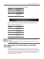
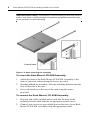
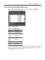
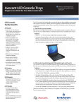
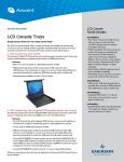
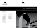
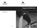
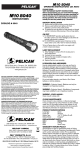
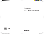
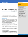
Rack Mount LCD KVM Assembly
Installer/User Guide
Japanese Notification
Chinese Notification
Taiwanese Notification
Rack Mount
LCD KVM Assembly
Installer/User Guide
Avocent, the Avocent logo and The Power of Being There are registered
trademarks of Avocent Corporation or its affliates in the U.S. and other
countries. All other marks are the property of their respective owners.
© 2010 Avocent Corporation. All rights reserved. 590-940-501C
Instructions
This symbol is intended to alert the user to the presence of important
operating and maintenance (servicing) instructions in the literature
accompanying the appliance.
Dangerous Voltage
This symbol is intended to alert the user to the presence of uninsulated
dangerous voltage within the product’s enclosure that may be of sufficient
magnitude to constitute a risk of electric shock to persons.
Power On
This symbol indicates the principal on/off switch is in the on position.
Power Off
This symbol indicates the principal on/off switch is in the off position.
Protective Grounding Terminal
This symbol indicates a terminal which must be connected to earth ground
prior to making any other connections to the equipment.
iii
TABLE OF CONTE NTS
Table of Contents
Chapter 1: Installation...............................................................1
Introduction.............................................................................................1
Getting Started ........................................................................................1
Installation ..............................................................................................1
Introduction of I/O ports for each model.........................................2
Rack Mounting Your Rack Mount LCD KVM Assembly.........................3
Using the hotkey functions ...............................................................5
Accessing and using the OSD menu ................................................7
Appendices ................................................................................ 9
Appendix A: Product Specifications .......................................................9
iv
Rack Mount LCD KVM Assembly Installer/User Guide
1
CHAP TE R
Installation
1
Introduction
Supporting both USB and PS/2 interfaces, the Rack Mount LCD KVM
Assembly can control up to 16 servers. Built-in keyboard, video and
mouse (KVM) peripherals not only save valuable cabinet space, but also
enable direct channel selection via on-screen display (OSD) or keyboard
hotkeys.
Time-out and password protection offer secure access to the Rack
Mount LCD KVM Assembly, while the hot-plug feature allows for
uninterrupted switching and usage.
NOTE: The Rack Mount LCD KVM Assembly is also referred to as “the assembly”
interchangeably throughout this installer guide.
Getting Started
Before installing your Rack Mount LCD KVM Assembly, refer to the
following list to ensure you have all items that shipped with the
appliance, as well as other items necessary for proper installation.
Supplied with the Rack Mount LCD KVM Assembly
•
Rack mount kit
•
Power cable
•
Ground terminator
Installation
If you are installing your Rack Mount LCD KVM Assembly to a PS/2
interface, you must turn off all servers before connecting your appliance
to a server for proper installation. USB interfaces do not need to be
turned off before installation.
2
Rack Mount LCD KVM Assembly Installer/User Guide
NOTE: Linux users may experience mouse failure if hot-plugging directly to the
assembly. If your mouse becomes locked, use the mouse reset hotkeys to reset
your mouse, or turn the Linux server off before connecting it to the assembly.
Introduction of I/O ports for each model
NOTE: For Taiwan customers only, 16-port models have the following model
numbers: AP17KMM16-101 and AP17KMM16-109; 8-port models have the
following model numbers: AP17KMM8-101 and AP17KMM8-109; and single-port
models have the following model numbers: AP17KMM-101 and AP17KMM-109.
Figure 1.1: Rear View of a 16-port Rack Mount LCD KVM Assembly
Table 1.1: Description of Figure 1.1
Number
Description
1
Power input socket
2
Power switch
3
Ground
4
Console port
5
PC connection
ports (16)
Figure 1.2: Rear View of an 8-port Rack Mount LCD KVM Assembly
Table 1.2: Description of Figure 1.2
Number
Description
1
Power input
socket
2
Power switch
Chapter 1: Installation
3
Table 1.2: Description of Figure 1.2 (Continued)
Number
Description
3
Ground
4
Console port
5
PC connection
ports (8)
Figure 1.3: Rear View of a single-port Rack Mount LCD KVM Assembly
Table 1.3: Description of Figure 1.3
Number
Description
1
Power input
socket
2
Power switch
3
Ground
4
PC connection
port (1)
CAUTION: To reduce the risk of electric shock or damage to your equipment:
- Plug the power cord into a grounded (earthed) outlet that is easily accessible at
all times.
- Disconnect the power from the unit by unplugging the power cord from either the
electrical outlet or the unit.
Rack Mounting Your Rack Mount LCD KVM
Assembly
Your Rack Mount LCD KVM Assembly may be rack mounted using
brackets. Before installing the assembly, stabilize the rack in a permanent
location. Be sure to rack your Rack Mount LCD KVM Assembly in an
area of the cabinet that will allow you to utilize the LCD monitor,
keyboard and mouse funtions.
4
Rack Mount LCD KVM Assembly Installer/User Guide
CAUTION: Rack Loading - Overloading or uneven loading of racks may result in
shelf or rack failure, causing damage to equipment and possible personal injury.
Do not exceed your rack load rating.
Rear of rack
Front of rack
Figure 1.4: Rack mounting the assembly
To mount the Rack Mount LCD KVM Assembly:
1.
Attach the front of the Rack Mount LCD KVM Assembly to the
front of your rack cabinet using the screws provided.
2.
Standing behind the assembly, slide the mounting brackets into the
slots on the side of the unit.
3.
Secure the brackets to the rear of the rack using the screws
provided.
To connect the Rack Mount LCD KVM Assembly:
1.
Plug one end of the supplied power cord into the back of the
assembly and the other end into an appropriate power source.
2.
Connect your servers to an available port on the rear of your Rack
Mount LCD KVM Assembly using the appropriate cable.
Chapter 1: Installation
3.
5
Turn on all connected servers. Keyboard and mouse recognition is
now activated and your Rack Mount LCD KVM Assembly is ready
for operation.
After installation, turn on your Rack Mount LCD KVM Assembly and
then any attached computer. The default password is not required,
simply press Enter to continue. Refer to the following table for a list of
push-button functions available via the LCD monitor.
Table 1.4: Monitor Push-button Functions
Button/LED
Description
AUTO EXIT
Exits from the OSD function or returns to
previous menu
SL (+ or -)
Moves the selector right or left on the OSD
menu
MENU SELECT
Enables the OSD menu and controls the
function to be adjusted
Turns your Rack Mount LCD KVM Assembly
on or off
LED (status light)
Green = On
Flashing Green = power save mode or
disconnection of signal cable
Red = Off
Using the hotkey functions
The 8-port and 16-port version of the Rack Mount LCD KVM
Assembly features hotkey commands that allow you to easily access
various functions of your assembly. The following table explains the
hotkey functions available.
NOTE: To utilize the hotkey functions in the following table, press the Ctrl key on
the left side of the keyboard twice, then press the keys for the desired command.
6
Rack Mount LCD KVM Assembly Installer/User Guide
Table 1.5: Hotkey Commands and Descriptions
Function
Port Switch
Keystrokes
Description
Left Ctrl + Left Ctrl + 1-8
Selects the desired port channel by
number (port 1-8)
Left Ctrl + Left Ctrl + F1 - F8 Selects port channels 9-16
Left Ctrl + Left Ctrl + Up or
Down Arrow
The Up Arrow selects the next
channel; the Down Arrow selects the
previous channel
Beep
Left Ctrl + Left Ctrl + B
Turns the beep function on or off in
Scan Mode (default is on)
Auto Scan
Left Ctrl + Left Ctrl+ S
Allows you to exit Auto Scan by
pressing any key
Reset
Assembly
Left Ctrl + Left Ctrl + R
Resets the LCD KVM assembly
Reset Mouse Left Ctrl + Left Ctrl + M
Resets the mouse
Reset
Keyboard
Left Ctrl + Left Ctrl + K
Reset the keyboard
OSD Menu
Left Ctrl + Left Ctrl +
spacebar (or double-click
the right mouse button)
Displays the OSD menu
NOTE: The two consecutive left Ctrl keystrokes and the following command
key(s) should be pressed within two seconds or the hotkey sequence will not be
validated. Port number selections must be made using the numeric keys on the
keyboard. Numeric keys on the keypad are not available as hotkey commands.
Chapter 1: Installation
7
Accessing and using the OSD menu
Right-click the mouse button twice or press Ctrl + Ctrl + Spacebar to
access the following OSD Menu.
Figure 1.5: OSD Menu
Table 1.6: OSD Menu Key
Heading
Description
NO.
Port numbers
On line
System on
QV
Quick view
Name
Port name
A single click on the left mouse button allows you to switch to a chosen
PC port. Use the up or down arrows to highlight your selection, and then
press Enter to make your selection.
8
Rack Mount LCD KVM Assembly Installer/User Guide
Table 1.7: OSD Functions
Function Key
Submenu/Description
LST
F1
All - Lists all ports
Power On - Lists only ports that have a PC turned on
Quick View - Lists only Quick View ports
Scan
F2
All - Scans all ports
Power On - Scans only ports that have a PC turned on
Quick View - Scans only Quick View ports
Set
F3
Scan Time - Sets scan time (default = 5 secs.)
Port Time - Sets port time (default = 5 secs.)
Console PWD - Sets console password (default = Enter)
Load Default - Sets load default values
Tool
F4
Reset KVM - Press Enter to reset the KVM assembly
Reset Mouse - Press Enter to reset the mouse
Reset Keyboard - Press Enter to reset the keyboard
Mouse On - Default is all ports. Toggle to Mouse Off and
press Enter to deselect available ports
Keyboard On - Default is all ports. Toggle to Keyboard Off
and press Enter to deselect available ports
QV
F5
Enables or disables Quick View
Name
F6
Displays active port name
Lock
Console
F8
Locks your KVM console
Exit
Esc
Allows you to quit the OSD menu
9
AP PE NDICE S
Appendices
Appendix A: Product Specifications
Table A.1: Rack Mount LCD KVM Assembly Specifications
LCD
LCD Type
XGA TFT
Display Area
17”
Resolution
1280 x 1024
Luminance
250 cd/m2 ( T Y P)
Contrast Ratio
800:1 ( T Y P)
Back Light
CCFL 2 lamps
Pixels Intervals (mm)
0.264 (H) x 0.264 (W)
LCD MTBF
> 50,000 hour
Power Input
5V DC
Power Consumption
< 40W
LCD OSD key
OSD Operation button
4 x Touch switches
LCD power source
1 x Sliding switch
Keyboard
Keys
82 keys + 17 number keys
Support IBM/AT
Supports Windows® Me/NT/2000/XP/7
Interface
PS/2 or USB
MTBF
> 10,000,000 times
Mouse
X/Y Resolution
>1000 point / inch, (40point/mm)
Hardware interface
PS/2 or USB
10
Rack Mount LCD KVM Assembly Installer/User Guide
Table A.1: Rack Mount LCD KVM Assembly Specifications (Continued)
Wheel
Supports wheel function
Operating System
Supports Windows® Me/NT/2000/XP/7
MTBF
> 10,000,000 times
Assembly (8-port and 16-port
versions)
PC Connection Ports
8 or 16
PC Selection
OSD Menu/Hotkey
Auto Scan Intervals
5-99 Secs
VGA Resolution
1920 x 1440
VGA Bandwidth
200 MHz
Power Supply
Alternating Current Input (A)
100-240VAC/50-60Hz/<1.5A
MTBF
>60,000 Hrs (25° C)
Dimensions
Net/Gross Weight
(1 port) 13.69 kg/GW 18.79 kg
(8 port) 14.63 kg/GW 19.43 kg
(16 port) 14.79 kg/GW 19.59 kg
Unit Dimensions (W x D x H)
448 mm x 545 mm x 43 mm (1 port)
448 mm x 600 mm x 43 mm (8 port)
448 mm x 600 mm x 43 mm (16 port)
Package Size (W x D x H)
765 mm x 615 mm x 185 mm
Temperature
0-45° C (Operating), -20 - 60° C (Storage)
Humidity
0-80%, Non-Condensing
For Technical Support:
www.avocent.com/support
590-940-501C