1
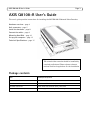
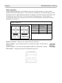
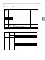
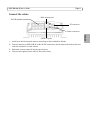
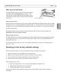
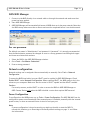
User’s Guide
ENGLISH
AXIS Q8108-R Network Video Recorder
About this Document
This document includes instructions for installing the
AXIS Q8108-R Network Video Recorder.
and fitness for a particular purpose. Axis
Communications AB shall not be liable nor responsible
for incidental or consequential damages in connection
with the furnishing, performance or use of this material.
Legal Considerations
Video and audio surveillance can be prohibited by laws
that vary from country to country. Check the laws in
your local region before using this product for
surveillance purposes.
RoHS
Electromagnetic Compatibility (EMC)
WEEE Directive
This equipment generates, uses and can radiate radio
frequency energy and, if not installed and used in
accordance with the instructions, may cause harmful
interference to radio communications. However, there is
no guarantee that interference will not occur in a
particular installation.
If this equipment does cause harmful interference to
radio or television reception, which can be determined
by turning the equipment off and on, the user is
encouraged to try to correct the interference by one or
more of the following measures: Re-orient or relocate
the receiving antenna. Increase the separation between
the equipment and receiver. Connect the equipment to
an outlet on a different circuit to the receiver. Consult
your dealer or an experienced radio/TV technician for
help. Shielded (STP) network cables must be used with
this unit to ensure compliance with EMC standards.
USA - This equipment has been tested and found to
comply with the limits for a Class B computing device
pursuant to Subpart B of Part 15 of FCC rules, which are
designed to provide reasonable protection against such
interference when operated in a commercial
environment. Operation of this equipment in a
residential area is likely to cause interference, in which
case the user at his/her own expense will be required to
take whatever measures may be required to correct the
interference.
Europe This digital equipment fulfills the
requirements for radiated emission according to limit B
of EN55022, and the requirements for immunity
according to EN55024 residential and commercial
industry.
Equipment Modifications
This equipment must be installed and used in strict
accordance with the instructions given in the user
documentation. This equipment contains no
user-serviceable components. Unauthorized equipment
changes or modifications will invalidate all applicable
regulatory certifications and approvals.
Liability
Every care has been taken in the preparation of this
document. Please inform your local Axis office of any
inaccuracies or omissions. Axis Communications AB
cannot be held responsible for any technical or
typographical errors and reserves the right to make
changes to the product and documentation without
prior notice. Axis Communications AB makes no
warranty of any kind with regard to the material
contained within this document, including, but not
limited to, the implied warranties of merchantability
This product complies with both the European
RoHS directive, 2002/95/EC, and the Chinese
RoHS regulations, ACPEIP.
The European Union has enacted a Directive
2002/96/EC on Waste Electrical and Electronic
Equipment (WEEE Directive). This directive is
applicable in the European Union member
states.
The WEEE marking on this product (see right) or its
documentation indicates that the product must not be
disposed of together with household waste. To prevent
possible harm to human health and/or the environment,
the product must be disposed of in an approved and
environmentally safe recycling process. For further
information on how to dispose of this product correctly,
contact the product supplier, or the local authority
responsible for waste disposal in your area.
Business users should contact the product supplier for
information on how to dispose of this product correctly.
This product should not be mixed with other commercial
waste.
Support
Should you require any technical assistance, please
contact your Axis reseller. If your questions cannot be
answered immediately, your reseller will forward your
queries through the appropriate channels to ensure a
rapid response. If you are connected to the Internet, you
can:
• download user documentation
• find answers to resolved problems in the FAQ database.
Search by product, category, or phrases
• report problems to Axis support by logging in to your
private support area.
AXIS Q8108-R User’s Guide
Page 3
AXIS Q8108-R User’s Guide
This user’s guide provides instructions for installing the AXIS Q8108-R Network Video Recorder.
ENGLISH
Hardware overview - page 4
Unit connectors - page 5
Install the hardware - page 8
Connect the cables - page 9
Mounting Hard Disk - page 10
Set up your computer - page 12
Technical Specifications - page 15
Important!
The network video recorder should be installed by
a trained professional. Please observe relevant
national and local regulations for the installation
Package contents
Item
Models/variants/notes
Network Video Recorder
AXIS Q8108-R
Printed materials
AXIS Q8108-R User’s Guide (this document)
Included accessories
Power cable with terminal block, Cable shelf
Not included accessory
Power supply, Cable sealing for IP65 rating
Page 4
AXIS Q8108-R User’s Guide
Hardware overview
Back cover
Front panel
Cable shelf
Screws to clamp cables
80 mm (3.1”)
294 mm (11.6”)
86 mm (3.4”)
178 mm (7”)
193.6 mm (7.6”)
211mm (8.3”)
17,5 mm (0.7”)
80 mm (3.1”)
80 mm (3.1”)
275 mm (10.8”)
Dimensions
AXIS Q8108-R User’s Guide
Page 5
Back
SATA power cable adapter
Hard disk bracket
Internal power button
Power LED indicators
1 Gbit network port
Network LED indicators
I/O connector
Power connector
8 x PoE network connectors
2 USB 2.0 ports
ENGLISH
SATA connectors
Battery
Front
PoE and Link LED indicators
Page 6
AXIS Q8108-R User’s Guide
Unit connectors
8 PoE network connectors - RJ-45 Ethernet connectors. Provides power to up to 8 network
cameras that are PoE enabled Class 1. The PoE ports are divided into a left and right group of four.
A maximum load of 16W is allowed per group. For example, a PoE class 0 can be connected in the
left group and up to 4 PoE class 1 can be connected in the right group. If a PoE class 0 is
connected, the other ports in the group must not be used. See illustration below and Technical
specifications on page 15.
Possible combinations
1
5
2
6
3
7
4
8
Right group
Left group
4 PoE class 1
4 PoE class 1
1 PoE class 0
1 PoE class 0
Max load = 16W Max load = 16W
Left group
Right group
Total
4 PoE Class 1
4 PoE Class 1
8
4 PoE Class 1
1 PoE Class 0
5
1 PoE Class 0
4 PoE Class 1
5
1 PoE Class 0
1 PoE Class 0
2
Network connector- 1 Gbit port for external network connection.
Power connector- 3-pin terminal block. Use a fused power supply: 12V DC (10A) or
24V DC (5 A)
2 USB 2.0 ports - To be used with any peripheral USB device. Max load = 500mA
I/O connector - 2 digital output ports and 8 digital input ports.
2 4
6 8 10 12
1 3 5
7 9 11
-
AXIS Q8108-R User’s Guide
Page 7
Pin assignment - I/O connector
Function
Notes
Specifications
Open collector NPN transistor with the emitter
connected to ground when activated.
Outputs are reserved for developer use.
Max load = 500mA
Inactive for voltages less than 1V
Active for voltages more than 3V
Only one input can be programmed via AXIS NVR
manager, see Power Configuration, on page 13
Max input = + 30V
Max load = 250mA
1
Output 1
2
Output 2
3
Input 1
4
Input 2
5
Input 3
6
Input 4
7
Input 5
8
Input 6
9
Input 7
10
Input 8
11
5V DC
Power
Can be used to power auxiliary equipment.
Note:
This pin can only be used as power out.
12
GND
Ground
ENGLISH
Pin
number
LED indicators
LED
Color
Indication
Network
Amber
Link established.
Green
Unlit
Steady for connection to 100 Mbit/s network
Green
Power supplied - normal operation.
Green and
Amber
Battery powered
Power
PoE/Link
For connection to 1Gbit/s network
Unlit
Power off
Green
Steady
Power is being supplied to the camera
Flash slowly
Short circuit
2 flash sequence
Error in PoE connection.
5 flash sequence
Connected units exceed the max load.
6 flash sequence
Connected units in the left or right group
exceed the max load.
Amber
Link established
Page 8
AXIS Q8108-R User’s Guide
Install the hardware
Before you begin
There are a few considerations before installing the AXIS Q8108-R.
•
The AXIS Q8108-R casing is designed to mount directly on any surface using a minimum of
4 screws appropriate for the surface type
• The operating temperature range is dependent on the Hard Disk
• Install in an open area allowing for 10mm of space on all sides for cooling and ventilation
• Ensure there is proper fuse protection: 12V DC (10A) or 24V DC (5 A)
1. Use at least 4 screws appropriate for the surface. The AXIS Q8108-R is designed to install in any
position, but if it is to be installed in a vertical position the cable shelf should be pointing up for
optimal heat dissipation.
p
Cables should point up when installing in the verical position
2.
3.
4.
5.
Thread the cables through cable shelf. For an IP65 rating use Cable Sealing (not included).
Connect all appropriate cables. See Connect the cables, on page 9.
Attach front cable shelf to AXIS Q8108-R with the four provided screws.
Tighten shelf to clamp cables. This prevents connector damage during operation.
AXIS Q8108-R User’s Guide
Page 9
Connect the cables
8 x PoE network connectors
1 Gbit network port
I/O connector
Power connector
1. Install up to 8 Axis network cameras according to their Installation Guides.
2. Connect cameras to AXIS 8108-R via RJ-45 PoE connectors, which will provide both power and
network connection to each camera.
3. Optionally connect external input/output devices.
4. Connect the supplied power cable to the power block.
ENGLISH
2 USB 2.0 ports
Page 10
AXIS Q8108-R User’s Guide
Mounting Hard Disk
AXIS Q8108-R supports the use of up to 2 separate hard disk. Follow these instructions and consult
manufacturer’s recommendations to mount or change hard disk.
1. Remove the back cover.
2. Power off the AXIS Q8108-R, see Start up and shut down, on page 11 and LED indicators, on
page 7.
3. Insert hard disks into adapter kit. It’s possible to use one 3.5” or up to two 2.5” hard disks.
4. Insert adapter kit with hard disks into the bracket in the lid.
5. Attach the SATA connectors.
6. Power on the device.
7. Replace back cover and tighten screws
1
2
3
AXIS Q8108-R User’s Guide
Page 11
Start up and shut down
The AXIS Q8108-R starts up automatically when power
is supplied. See AXIS NVR Manager, on page 13 for
more options. The AXIS Q8108-R automatically does a
controlled shut down after one minute when the power
is shut off.
Internal power button
Internal power button
The internal power button is also used for resetting the NVR to factory default settings, see
Resetting to the factor default settings.
Battery backup function
The AXIS Q8108-R has an Uninterruptable Power Supply (UPS) designed for short power shortages.
For periods more than 1 minute, the UPS will provide enough power to the AXIS Q8108-R for a
controlled shut down.
A controlled shutdown may not occur if the battery temperature is outside of charging range 0 45°C (32 - 113°F).
Resetting to the factory default settings
This will reset parameters to the factory default settings including the password.
1.
2.
3.
4.
Disconnect power from the NVR and remove back cover.
Make sure all indicator LEDs are off (this could take a few moments).
Press and hold the Internal power button and reconnect power.
Release the Internal power button when the power LED is lit.
These settings will be reset:
• Network configuration is set to factory default (DHCP and UPnP™ off)
• Administrator password is set to "password"
• Power Configuration is set to "Automatic"
Resetting the NVR to factory default settings will not affect AXIS Camera Station settings or
recordings.
ENGLISH
Use this button to manually start up or shut down the AXIS Q8108-R. When pushed briefly the NVR
will power down in a controlled manner, which will take 15 - 30 seconds. If the button is held down
for more than 3 seconds the NVR will hard power down. This is useful if for some reason the NVR
becomes unresponsive.
Page 12
AXIS Q8108-R User’s Guide
Set up your computer
This section will help you install AXIS NVR Manager and AXIS Camera Station Client and configure
it for your Axis NVRs and Axis Network Cameras. A brief introduction to the functionality of the
software is covered here. For more information see the context sensitive help files or, for AXIS
Camera Station see the User’s Manual available at www.axis.com
AXIS NVR Manager is for discovery, configuration and firmware upgrade of AXIS Q8108-R. Go to
www.axis.com to download AXIS NVR Manager and follow the install wizard’s instructions. Make
sure you have full administrator rights on the computer you install on.
AXIS Camera Station Client is for monitoring, recording, playback and event management of Axis
network cameras. Launch AXIS Camera Station Client from AXIS NVR Manager and follow the
install wizard’s instructions or download from www.axis.com.
Minimum recommended requirements for AXIS NVR Manager and AXIS Camera Station Client
PC minimum requirements:
•
•
Memory: 1 GB RAM
Software: Windows XP SP2, Server 2003 SP2, Vista, Windows 7 (For other operating systems, see www.axis.com/techsup), Microsoft .NET 3.5 (included in installation package)
• Support for DirectX 9.0c
For individual PC requirements for AXIS Camera Station Client refer to the AXIS Camera Station
User’s Manual.
AXIS Q8108-R User’s Guide
Page 13
AXIS NVR Manager
1. Connect to the NVR directly via a network cable or through the network and make sure that
power has been applied.
2. Start AXIS NVR Manager.
3. AXIS NVR Manager will automatically discover all NVRs that are in the same network. Note that
the NVR startup takes more than a minute and must be completed before it can be discovered.
ENGLISH
Set the password
The default user name is “Administrator” and password is “password”. It is strongly recommended
that the Administrator password be changed at once to a strong password containing both upper
and lower case letters and numbers.
1. Select the NVR in the AXIS NVR Manager window.
2. Go to Tools > Set Master Credentials.
3. Enter a strong password.
Network configuration
Network settings can be assigned either automatically or manually. Go to Tools > Network
Configuration
To access the NVR from behind a router UPnP™ must be enabled in AXIS NVR Manager. Check
Enable UPnP™ under Network Configuration. When enabling UPnP™, the NVR needs to be in the
subnet as your computer. Make sure that the router is UPnP™ capable and has UPnP™ enabled.
Caution:
For security reasons, enable UPnP™ in order to access the NVR via AXIS NVR Manager or
AXIS Camera Station only when the NVR is behind a router that requires NAT traversal.
Power Configuration
To configure how the NVR powers on, go Tools > Power Configuration. The AXIS Q8108-R can be
configured to power on automatically when external power is available, manually with the internal
power button, or when an external button is wired to an input port.
Note:
If power configuration is done incorrectly you might not be able to start the NVR. To
remedy this situation go to Resetting to the factory default settings, on page 11 and follow
the instructions.
Page 14
AXIS Q8108-R User’s Guide
AXIS Camera Station
AXIS Camera Station Client is for monitoring, recording, playback and event management.
Connect AXIS Camera Station Client
From AXIS NVR Manager select an NVR device and click the Launch AXIS Camera Station Client
icon or start AXIS Camera Station Client from your computer and use the NVR’s network address in
the logon dialog.
Notes:
• If the correct version of AXIS Camera Station Client has not been previously installed on the
computer running AXIS NVR Manager, a prompt will appear to perform an installation.
• Prior versions of AXIS Camera Station Client and AXIS Camera Station Server need to be removed
from the computer before installing this version. Do not continue with the installation if the removal
of prior versions is not your intent.
To log onto the NVR enter the administrator user name and password you set up in NVR Manager
see Set the password, on page 13.
Configure AXIS Camera Station
For easy navigation AXIS Camera Station is divided into workspaces; Live view, Recordings, Logs
and Configuration.
•
•
•
•
Live view - Provides a single interface to organize and monitor AXIS network cameras
and video encoders on your network
Recordings - Search, playback and export recordings from one or many cameras in a
desired time interval with timeline visualization
Logs - Alarm, event and audit logs for an instant overview of the system
Configuration - has a collection of all the important links to add cameras, set up
recording settings, user permissions, event configuration and more
When AXIS Camera Station is started for the first time it automatically adds Axis cameras and video
encoders it finds on your network. If there are more cameras on your network than you have a
license for, go to Configuration > Add/Edit Cameras.
Note:
To use the NVR as an NTP server for the added cameras, use the NVR’s IP address.
For more information see the context sensitive help in AXIS Camera Station or the User’s Manual.
AXIS Q8108-R User’s Guide
Page 15
Technical Specifications
Function/
group
System
Software
General
Specification
Model
AXIS Q8108-R
Processor
1.1GHz Intel Atom Z5 series CPU
RAM
1GB SODIMM DDR2
System disk
Compact Flash PATA drive 4GB
Operating system
Windows Embedded Standard 2009
Battery backup
Controlled shutdown 1 minute after power loss
Security
Password protection, user access log
NTP
NTP server included
Video Management
Software
AXIS Camera Station, 8-channel license included.
For more information, see www.axis.com/products/
cam_station_software
Application
Programming
Interface
Open API for software integration
Video compression
H.264 (MPEG-4 Part 10/AVC), MPEG-4 Part 2,
Motion JPEG
Audio compression
AAC,G.711, G.726
Resolutions
Supports connected Axis video product resolutions
Recording frame rate
Supports connected Axis video product frame rates
(Maximum total recording bit rate 70 Mb/s)
Casing
Rugged IP43 rated aluminum casing
Input voltage
12 or 24V DC
Max power
84 W
PoE output
8 PoE class 1, or 1 PoE class 0 + 4 PoE class 1, or 2
PoE class 0
Connectors
2x high speed USB ports, 1x Gbit port for external
connection, 8 RJ-45 10BASE-T/100BASE-TX PoE,
2 digital output ports and 8 digital input ports,
2 SATA connectors
Operating
Temperatures
-10 to 50 ºC (14 - 122 ºF)
Weights
3.7 kg (8.14 lb)
ENGLISH
Network
Item
Page 16
Function/
group
AXIS Q8108-R User’s Guide
Item
Specification
Approvals
EU directive 2002/96/EC, MIL STD-810F Method
516.5 Procedure I, MIL STD-810F method 514.5, EN
55022, EN 55024, EN 61000-4-2, ISO 11452-2, EN
61000-4-3, ISO 11452-2, EN 61000-4-4, EN 610004-5, EN 61000-4-11, ISO 7637-2, EN50121-3-2,
FCC part 15 subpart B class B
Project customization WLAN 802.11b/g, GSM/UMTS/HSDPA, GPS,
Accelerometer
User’s Guide
AXIS Q8108-R
© Axis Communications AB, 2010
Ver.1.0
Printed: August 2010
Part No. 39382


![WLg-ABOARD /N[P] - ACKSYS Communications & Systems](http://vs1.manualzilla.com/store/data/006361248_1-d85c19beabe1f63c614e17883b6a3a3e-150x150.png)