1
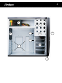
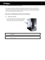
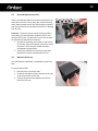
SONATA III
USER’S MANUAL
1
TABLE OF CONTENTS
SECTION 1: INTRODUCTION
1.1
Getting to Know Your Case…………………………………………………………………………………. 3
1.2
Case Specifications……………………………………………………………………………………………… 5
1.3
Parts Included…………………………………………………………………………………………………….. 5
1.4
Before You Begin………………………………………………………………………………………………… 6
2.1
Locating and Positioning Your Computer……………………………………………………………. 7
SECTION 2: INSTALLING HARDWARE
2.4
Removing the Side Panel…………………………………………………………………………………….. 7
2.2
Cable Management…………………………………………………………………………………………….. 8
2.3
Motherboard Installation……………………………………………………………………………………. 8
2.4
Internal 3.5” Drive Bay Device Installation………………………………………………………….. 9
2.5
External 3.5” Drive Bay Device Installation…..…………………………………………………….. 10
2.6
External 5.25” Drive Bay Device Installation……………………………………………………….. 10
SECTION 3: CONNECTING THE FRONT I/O PORTS
3.1
USB 2.0 Ports………………………………………………………………………………………………………. 11
3.2
AC’97 / HD Audio Ports………………………………………………………………………………………..11
3.3
Power Switch/Reset Switch/Hard Disk Drive LED Connectors……………………………… 12
3.4
Rewiring Motherboard Header Connections...……………………………………………..…….. 12
SECTION 4: COOLING SYSTEM
4.1
TriCool™ Fan………………………………………………………………………………………………………..13
4.2
Installing an Additional Fan…………………………………………………………………………………. 14
4.3
Washable Air Filters……………………………………………………………………………………………. 14
SECTION 5: COMMONLY ASKED QUESTIONS
Commonly Asked Questions……………………………………………………………………………….. 15
2
SONATA III 500 USER’S MANUAL
Congratulations on your purchase of the Antec Sonata III 500!
Your Sonata III 500 is designed to be the quietest, easiest-to-use case on the market. The Sonata III 500
is powered by EA-500D Green power supply unit equipped with Universal Input and Active PFC, which
allows you to connect your power supply to any AC power outlet between 100V and 240V as well as
reducing electrical waste.
At Antec, we continually refine and improve our products to ensure the highest quality. It’s possible that
your new case will differ slightly from the descriptions in this manual. This isn’t a problem; it simply
indicates an area where we’ve improved the design. As of the date of publication, all features,
descriptions, and illustrations in this manual are correct.
Grab your case and components… let’s get building!
Disclaimer
This manual is intended only as a guide for Antec’s computer enclosures. For more comprehensive
instructions on installing the motherboard and peripherals, please refer to the user’s manuals that come
with those components.
3
INTRODUCTION
1.1
GETTING TO KNOW YOUR CASE
1. 120mm rear TriCool™ fan
Positioned at the rear of your case. Draws warm air through the interior of the case and out the
back. See Section 4.1 for more detail.
2. 120mm front fan mount
A fan mounting location is provided for mounting fans up to 120mm in size. See Section 4.2 for more
detail.
3. Washable air filter
This filters out dust from the air entering your computer case. For removal and washing instructions,
see Section 4.3.
4. Motherboard standoffs
Motherboard standoffs are included with your case. These will match up with the standard
mounting holes in Mini-ATX, MicroATX and ATX motherboards only.
5. Cable routing compartment
This area is provided for you to tuck away unneeded connectors and cables.
6. Power supply mount
This secures your power supply to your case. In the Sonata III 500, this is already occupied by the
included Earthwatts EA-500D Green PSU.
7. 5.25” drive bays
These bays allow the installation of optical drives as well as accessories like front panel audio
controls, card readers designed to fit into a 5.25” bay.
8. Front I/O panel
Contains AC’97/HDA-compatible 3.5mm audio, USB 2.0 and eSATA ports.
9. External 3.5” drive bays
These bays allow external installation of 3.5” bay-compatible storage accessories.
10. Internal 3.5” drive bays
These bays allow installation of 3.5” bay-compatible storage accessories.
4
6
7
5
1
8
9
2
10
4
3
5
1.2
CASE SPECIFICATIONS
Case Type
Mid Tower
Color
Gloss Black
19.5 " (H) x 10.5" (W) x 21.5" (D)
495mm (H) x 266.7mm (W) x 495mm (D)
9.1kg / 20.2 lbs
Dimensions
Weight
Cooling
1 x Rear 120mm TriCool™ LED fan
1 x Front 120mm fan mount (optional)
Drive Bays
10 Drive Bays:
- 3 x External 5.25” drive bays
- 2 x Internal 3.5” drive bays
- 4 x Internal 3.5” drive bays
Expansion Slots
7
Motherboard Size
Mini-ITX, microATX, Standard ATX
2 x USB 2.0
External eSATA
AC’97 / HD Audio In and Out
Front I/O Panel
1.3
PARTS INCLUDED
In addition to the accessories stored inside your computer, your box should also contain the following:
Illustration No.
1
2
3
4
5
6
7
8
9
1
2
Part
Front/Side panel keys
Screws for 5.25” bay drive bay screw
HDD screws (grommets already inserted in drive trays)
Fan screw
Motherboard standoffs
Motherboard screws
Misc for screws
Optical drive screws
Case decal
Clear silicone grommets (already installed in drive trays)
3
4
5
6
7
8
Qty
1
2
16
4
9
13
4
16
1
9
6
1.4
BEFORE YOU BEGIN
In order to ensure that your building experience with the Sonata III 500 will be a positive one, please
take note of the following:
•
While working inside your Sonata III 500, keep your case on a flat, stable surface. Keep a clean,
dust-free environment for building your computer.
•
Antec case interiors feature rounded edges that minimize the occurrence of hand injuries.
Nonetheless, we strongly recommend taking the appropriate time and care when working inside
the case. Avoid hurried or careless motions. Please use reasonable precautions.
•
Handle components and cards with care. Do not touch the components or contacts on a card.
Hold a card by its edges. Hold a component such as a processor by its edges, never by its pins.
•
To avoid electrostatic discharge, ground yourself periodically by touching an unpainted metal
surface (such as a connector or screw on the back of this computer) or using a wrist grounding
strap.
•
Before you connect a cable, ensure that both connectors are correctly aligned and oriented.
Bent pins can be difficult to fix and may require replacement of the entire connector.
•
This manual is not designed to cover CPU, RAM, or expansion card installation. Please consult
the motherboard manual for specific mounting instructions and troubleshooting. Before
proceeding, check the manual for your CPU cooler to find out if there are steps you must take
before installing the motherboard.
•
Do not sit on your case. Although it is constructed of heavy-duty steel and internally reinforced,
it is not intended to support the weight of an adult. Buckling or dimpling of the case walls may
result.
•
Remember to use the right tools for each task. Do not use improvised screwdrivers like coins,
nails or knife blades as they may result in damage to screw threads or even injury. Do not use
your fingernails to separate edges or lift the sides of the case, as paint chipping or injury may
occur.
•
Lastly… have fun!
TIP: In order to increase the precision of your hands, you may find it helpful to brace your elbows
against the table, or against your abdomen. Move the components you’re working with in a direction
parallel to the front of your body, using as many arm muscles as possible. Breathe in a relaxed,
controlled fashion.
7
1.5
LOCATING AND POSITIONING YOUR COMPUTER
Your Antec Sonata III 500 has a backwards-facing exhaust fan and two air intakes on the sides of the
front panel. For optimum performance, we recommend leaving the front air intakes unobstructed. The
Sonata III 500 can operate resting sideways as well as vertically. Do not rest the Sonata III 500 upside
down, as this will impede operation of optical drives.
SECTION 2: HARDWARE INSTALLATION GUIDE
2.1
1.
REMOVING THE SIDE PANEL
Remove the side panel by first lifting the latch located at
the rear of the case. Then, grip the side panel with the
latch and lift it away from the case until it detaches.
Caution:
The front panel is not removable. Please do not attempt to remove or pry open the
front panel.
Caution:
Do not use your fingernails to lift or pry open the panel. Injury or damage to the case
finish may result.
8
2.2
CABLE MANAGEMENT
There is a cable management compartment behind the 3.5” drive cage.
You can tuck or route excess cables in this compartment. This will keep
the cables from interfering with airflow in your case and help with
cooling.
1.
2.
3.
4.
Open the side panel as described in section 2.1.
Locate the cable management compartment with cable ties
located behind the walls of the external 3.5” drive cage.
Tuck or route your excess cables to the compartment.
Use cable ties to hold them in place.
2.3
MOTHERBOARD INSTALLATION
The Sonata III 500 comes with four motherboard standoffs
already screwed in to the most common mounting locations.
1.
2.
3.
4.
5.
6.
Lay the case down, with the open side facing up.
The drive cages should be visible on the right side of
the case, with the power supply in the upper left.
Make sure you have the correct I/O panel for your
motherboard. If the panel provided with the case
isn’t suitable, please contact your motherboard
manufacturer for the correct I/O panel.
Align your motherboard with the standoff holes and
remember which holes are lined up. Not all
motherboards will match with all the provided
holes; this is normal and won’t affect functionality.
Now remove your motherboard by lifting it up.
Install standoffs if needed and put the motherboard
back in.
Screw in your motherboard to the standoffs with
the provided Phillips-head screws.
Caution:
Make sure to remove any unused motherboard standoffs. They may come into contact
with the back of the motherboard and electrify your case exterior if left connected.
Note:
The Sonata III 500 comes with a CPU cutout on the motherboard tray, which will allow
you to mount oversize CPU heatsinks, and also change your CPU heatsink without
removing the motherboard.
Note:
The motherboard tray has standoffs pre-installed for the most common ATX mounting
locations. Extra standoffs and screws are included.
9
2.4
INTERNAL 3.5” DRIVE BAY DEVICE INSTALLATION
The Sonata III 500 provides space for up to four internal 3.5”
hard drives. Before you begin, remove the side panel as
described in section 2.1.
1.
2.
3.
With your thumb and forefinger, grasp the pinch tabs on
either side of one of the internal 3.5” drive trays, and slide
the drive tray outwards.
Mount your hard drive onto the internal 3.5” drive tray
with the hard drive’s sockets facing towards the back of
the tray.
Align and fasten the screw holes at the bottom of
the hard drive with the holes in the included
silicone grommets, using the included internal 3.5”
drive tray screws.
Caution:
4.
5.
6.
Do not torque or over-tighten the 3.5” internal drive tray screws. Compressing the
screws against the silicone grommets will reduce their lifespan and will lessen or negate
their vibration-insulating effect. Tighten the screws until you feel resistance, then stop.
Grasping the pinch tabs on either side of the
internal 3.5” drive tray, partially insert the drive tray
containing your 3.5” hard drive into the case.
Attach the Molex power leads from the PSU and the
hard drive cable from your motherboard to the back
of the hard drive.
Push the 3.5” drive tray containing your hard drive
into the case all the way until it clicks and locks into
place.
10
2.5
EXTERNAL 3.5” DRIVE BAY DEVICE INSTALLATION
The Sonata III 500 provides space for two external 3.5”
devices. Before you begin, remove the side panel as described
in section 2.1.
1.
2.
3.
4.
5.
2.6
With your thumb and forefinger, grasp the pinch tabs on
either side of one of the external 3.5” drive trays, and
slide the drive tray outwards.
Remove the screws from the top or bottom panel of the
external 3.5” drive tray. Gently pinch together the sides
of one of the drive tray’s drive covers and remove it from
the drive tray.
Place your 3.5”device in the tray. Using the screws
provided with the drive tray, securely fasten your
3.5” device to the tray.
Place the 3.5” external drive tray assembly
containing your 3.5” device into the front panel,
and push until it clicks.
Attach power and motherboard cables to the device
as necessary.
EXTERNAL 5.25” DRIVE BAY DEVICE INSTALLATION
The Sonata III 500 provides space for three external 5.25”
devices. Before you begin, remove the side panel as described
in section 2.1.
1.
2.
3.
With two forefingers, press the pinch tabs on either side
of one of the external 5.25” drive covers and pull the
cover out of the case.
Slide your 5.25” device into the drive bay, making sure to
engage the 5.25” drive tray rails on either side of the
bay.
Connect the power and motherboard cables to your
5.25” device.
11
SECTION 3: CONNECTING THE FRONT I/O PORTS
3.1
USB 2.0 PORTS
Connect the front I/O panel USB cable to the USB header pin on your motherboard. Check the
motherboard user’s manual to ensure that it matches the table below:
1
2
9 10
3.2
Pin
Signal Names
Pin
Signal Names
1
USB Power 1
2
USB Power 2
3
Negative Signal 1
4
Negative Signal 2
5
Positive Signal 1
6
Positive Signal 2
7
Ground 1
8
Ground 2
9
Key (No Connection)
10
Empty Pin
AC’97 / HD AUDIO PORTS
There is an Intel® standard 10-pin AC’97 connector and an Intel® 10-pin HDA (High Definition Audio)
connector linked to the front panel of the case.
10 6 4 2
9 7 5 31
Pin
Signal Names
(HDA)
Pin
Signal Names
(AC’97)
1
MIC2 L
1
MIC In
2
AGND
2
GND
3
MIC2 R
3
MIC Power
4
AVCC
4
NC
5
FRO-R
5
Line Out (R)
6
MIC2_JD
6
Line Out (R)
7
F_IO_SEN
7
NC
8
Key (no pin)
8
Key (no pin)
9
FRO-L
9
Line Out (L)
10
LINE2_JD
10
Line Out (L)
You can connect either the AC’97 or the HDA connector, depending on your motherboard. Locate the
internal audio connectors from your motherboard or sound card and connect the corresponding audio
cable. Consult your motherboard or sound card manual for the pin-out positions. Even if your system
supports both standards, only use one connector.
12
3.3
POWER SWITCH / RESET SWITCH / HARD DISK DRIVE LED CONNECTORS
Connected to your front panel are LED and switch leads for power, reset, and
HDD activity. Attach these to the corresponding connectors on your
motherboard. Consult your motherboard manual for specific pin header
locations. For LEDs, colored wires are positive ( + ). White or black wires are
negative ( – ). If the LED does not light up when the system is powered on, try
reversing the connection. For more information on connecting LEDs to your
motherboard, see your motherboard user’s manual.
Tip:
Polarity (positive and negative) does not matter for switches.
3.4
REWIRING MOTHERBOARD HEADER CONNECTIONS
There may come a time when you need to reconfigure the pin-out of a
motherboard header connector. Examples could be for your USB header, audio
input header, or some other front panel connector such as the Power Button
connector.
Before performing any work, please refer to your motherboard user’s manual
or your motherboard manufacturer's website to be sure of the pin-out needed
for your connector. We strongly recommend making a notated drawing before
beginning work so that you can recover if your work gets disturbed.
1.
2.
3.
Determine which wires you need to remove in order to rewire your
plug to match the USB pin-outs on your motherboard (refer to your
motherboard user’s manual). Working on one connector at a time,
use a very small flathead screwdriver or similar tool to lift up on
the black tab located beside the gold posts (squares). This will
allow you to easily slide out the pins from the USB plug.
Working carefully so as not to damage the wires, connectors, or
pins, slowly remove the pin from the connector. Repeat these
steps for each wire you need to change.
Slowly, carefully reinsert the pin into the correct slot of the
connector then snap closed the black tab that was lifted in step 1.
Repeat these steps for each wire you need to change.
13
SECTION 4: COOLING SYSTEM
4.1
TRICOOL™ FAN
Top TriCool™ Fan – The case comes with a 200mm top exhaust blue LED fan. The fan is installed so the
air will be blown out of the case. This fan comes with a three-speed switch that let you choose the speed
best suited to your need. The default fan speed setting is Low.
120mm TriCool™ Specifications
Size:
120 x 25mm TriCool™ fan
Rated Voltage:
12V
Operating Voltage:
10.2V - 13.8V
The Sonata III 500 comes with one pre-installed 120 x 25mm TriCool™ fan, located at the back of the
case. This fan is installed to blow warm air out of the case. The TriCool™ fan comes with a speed control
device attached to the fan housing. The default fan speed is Low.
Speed
(RPM)
Input
Current
Air Flow
Static
Pressure
Acoustic
Noise
Input
Power
High
2000
0.24A
(Max.)
2.2 m³ / min
(79 CFM)
2.5mm-H2O
(0.10 inch-H2O)
30 dBA
2.9 W
Medium
1600
0.20A
1.6 m³ / min
(56 CFM)
1.5mm-H2O
(0.06 inch-H2O)
28 dBA
2.4 W
Low
1200
0.13A
1.1 m³ / min
(39 CFM)
0.9mm-H2O
(0.04 inch-H2O)
25 dBA
1.6 W
Note: The minimum voltage to start a typical TriCool™ fan is 5V. We recommend that you set the fan
speed to High if you choose to connect the fan(s) to a fan control device or to the Fan-Only
connector found on some Antec power supplies. A fan control device regulates the fan speed by
varying the voltage, which may start as low as 4.5V to 5V. Connecting a TriCool™ fan set on Low
to a fan-control device may result in the fan not being able to start because the already lowered
voltage from the fan control device will be further reduced by the TriCool™ circuitry below 5V.
14
4.2
INSTALLING AN ADDITIONAL FAN
There is one optional 120mm fan mount located at on the
side of the internal 3.5” drive bays. We recommend using
Antec 120mm speed control fans and setting the speed to
Low. These fans must be installed so that the air is blowing
into the case.
Front Fan – A front fan can be used to enhance graphics
card cooling. The fan should be installed to pull air into
the front of the case. To install the front fan, first remove
the side panel as described in section 2.1.
1. Find the fan mounting screw holes on the interior
of the case. They are located on the interior of the
internal 3.5” drive bay rails, below the cable
management compartment.
2. Secure your 120mm fan to the four screw holes
using the fan screws provided with the case.
4.3
WASHABLE AIR FILTERS
Your case features a washable, removable front panel air
filter.
To remove the air filter:
1. Rest the case on its back or side.
2. Locate the two black air filter retention pinch tabs
at the front bottom of the case.
3. Pitch the outermost tabs together and pull the
filter from the case.
15
SECTION 5: COMMONLY ASKED QUESTIONS
My case is missing drive rails.
Check the back of the 5.25” drive bezel. They should be located there. If you see purple or black, it’s
there.
My side panel is locked in place.
If the side panel appears to be stuck in the locked position, place the case down with the left panel
facing up. Push and pull on the lever with gentle, firm pressure and it will come off. Your case is built
with very close manufacturing tolerances, and slight contraction or expansion from heating may cause
the side panel’s paint to seal closed against the case. Please place a mat or some soft cloth under the
case panels to avoid scratching your finish.
My computer shorts out and turns off when I touch the front USB or audio panel
If you have an original or early version of the Sonata III series that is silver in color, please call customer
support to obtain a black plate cover for the front ports.
What size graphics card can I put into the Sonata III 500?
The maximum graphics card length is 10.5 inches.
What is the middle port I see in front of the case?
The middle port is an unpowered eSATA port which allows high-speed data transfer. In order to utilize
this connector, you will need a motherboard that supports eSATA as well as the cable.
Does the TriCool fan connect to the motherboard or the power supply?
The fan is intended to connect directly to the power supply through the included 4-pin Molex connector.
I lost my keys.
Please call 1-800-222-6832 to obtain another set. Charges may apply.
Can I open the front door all the way to the left side panel?
No. Damage to the hinge or front door may result.
The power supply will not run my ATI/Nvidia/other manufacturer graphics card.
The PSU may not support power output level that the graphics card requires. Please check for
compatibility. You will need to know the power wattage and amperage requirements of your video card.
Please call 1-800-222-6832 for support.
I plugged in the AC power and my power supply will not start.
Your PSU requires a minimum level of power draw to start. Check to see if PSU is connected to the
motherboard and all of its main connections as well as any peripherals or accessories you may wish to
use.
When I push the front power button, my computer will not start.
There may be a mis-wired or faulty connection. Carefully check the front panel connections and firmly
re-attach as necessary. To confirm if a problem exists with the power supply lead, pull the power switch
16
header out and use the Reset switch temporarily. If the system boots up, then the power lead switch
may be faulty. Please call 1-800-222-6832 and obtain a replacement switch.
Do I need more fans to cool my system?
In most cases, no, you do not need more fans to cool your system. Please note, however, that the
Sonata III 500 was designed for standard usage levels, and extensive addition of high-temperature
hardware may adversely affect cooling performance. If you do decide to upgrade to a substantially
higher-temperature configuration, please make sure you have ample cooling by adding another fan
using the provided fan mount, or adding another third party cooling system.
Can the Sonata III 500 fit a Micro-ATX/Mini-ITX board?
All our cases are designed to Intel specifications and are backwards compatible with older case
standards – so, yes.
My power supply fan is not running.
Please contact 1-800-222-6832 for RMA service.
What is my warranty?
The Sonata III 500 and the EA-500D Green PSU have a three-year limited warranty on parts and labor.
Please check our warranty information at:
http://www.antec.com/Believe_it/index.php?page=warranty_info&AQ=AQ3&value=en
If I am shipping back my PSU, do I need to ship my case as well?
No, you only need to ship the defective PSU back.
17
Antec, Inc.
47900 Fremont Blvd.
Fremont, CA 94538
USA
tel: 510-770-1200
fax: 510-770-1288
Antec Europe B.V.
Stuttgartstraat 12
3047 AS Rotterdam
Netherlands
tel: +31 (0) 10 462-2060
fax: +31 (0) 10 437-1752
Customer Support: US & Canada
1-800-22ANTEC
[email protected]
Europe
+31 (0) 10 462-2060
[email protected]
www.antec.com
© Copyright 2009 Antec, Inc. All rights reserved.
All trademarks are the property of their respective owners. Reproduction in whole or in part without
written permission is prohibited.