1
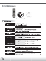
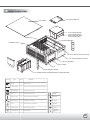
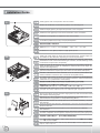
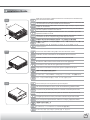
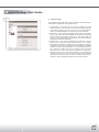
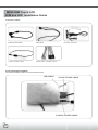
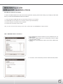
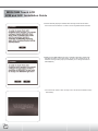
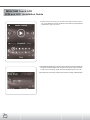
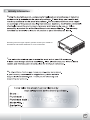
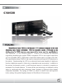
Product overview
CW03
Introduction
SilverStone’s Crown CW03 is a full featured HTPC enclosure designed for the most
discerning home theater enthusiasts. With the venerable Lascala LC18 model as the
starting point, the CW03 improves every aspect of the former case from specification to
user impression. LC18’s excellent grade-A 7” Hitachi LCD is retained, but additional
engineering breakthroughs enable CW03’s integrated LCD to now support resolutions
up to an incredible 1920 x 1200 pixels, a feat never before seen in a screen of its size.
This specification allows CW03’s to be used in conjunction with any full HD television on
the market. Supplementing the LCD is an advanced touch panel capable of digital pen
function (digital pen support in Vista only) or standard mouse movements. In addition to
the primary touchscreen control, a multi-functional remote is included to complete an
impressive list of media features. To house all the new technology, an intelligent cooling
layout is reinforced with thick aluminum frame finished to high-end home theater
component standards. The styling of CW03 is a blend of classic lines and high-tech
looks, making it the perfect flagship chassis for SilverStone’s Crown series.
02
Remote control, CDs
03
Product overview
5.25” DOCKING BAY
TOP PANEL
5.25” DOCKING BAY
5.25” DOCKING BAY
CAN CONVERT INTO
3.5” DOCKING BAY
80MM FAN
MOTHER BOARD
POWER SUPPLY
OPTICAL DRIVE UPPER COVER
5.25” DOCKING BAY COVER
7” TOUCH SCREEN
KEY PANEL
IR
ROCKMOUNT EARS
3.5” HARD DRIVE CAGE(MAXIMUN 6 HARD DRIVES)
PICTURE
ITEM
PIECE
PURPOSE
Remote
1
System remote
D-SUB 15P M/M
1
Connect monitor and graphic card to deliver the signal
1
IR remote to power on/off
cable
3
Convert 3pin fan to 4 pin
Rockmount ears
2
For placing to rack mount cabinet
SCREWS
Digital touch pen
1
Operating on touchscreen
SCREWS
CD-rom
2
Driver/software for touchscreen
SCREWS
Installation guide
1
System installation guide
WASHER
Included package
1
Assemble parts
VIBRATION
DAMPENING
PAD
Power supply 24p
extension cable
Fan converting
MOTHERBOARD
STANDS
04
This is a unique product, please read the following detailed
installation guide we have prepared meticulously for you.
01
Remove screws and top panel as shown
Loesen Sie die Schrauben des Deckels um diesen abzunehmen
Destornille los tornillos y saque el panel superior com se muestra.
Retirez les vis et le panneau supérieur comme montré
Estrarre le viti ed il pannello superiore come mostrato
Открутите шурупы и снимите верхнюю панель, как показано на
рисунке.
請依圖示卸下螺絲與上蓋
図のようにネジと上部パネルを外します。
그림에서와 같이 나사와 상부 패널을 제거하십시요.
02
Remove the three screws and the upper optical drive bracket
Loesen Sie die drei Schrauben am oberen Rahmen des optischen Laufwerks
Destornille los tres tornillos y saque la abrazadera del disco óptico superior
Retirez les trois vis et le casier à lecteur optique du dessus
Svitare le tre viti ed il supporto dell’unitá ottica superiore
Открутите три шурупа и снимите верхний кронштейн оптического диска.
請依圖示卸下三顆螺絲與上層光碟機機架
ネジ3本を外し、上側光学ドライブブラケットを外します。
3개의 나사와 상부 광 드라이브 브라켓을 제거하십시요.
03
Remove the screws and main optical drive bracket
Loesen Sie die Schrauben am Rahmen des optischen Hauptlaufwerks
Destornille los tornillos y saque la abrazadera del disco óptico principal
Retirez les vis et le casier à lecteur optique principal
Svitare le viti ed il disco ottico principale
Открутите шурупы и снимите верхний кронштейн главного оптического диска.
請依圖示卸下螺絲與主光碟機機架
ネジおよびメイン光学ドライブブラケットを外します。
나사와 메인 광 드라이브 브라켓을 제거하십시요.
05
Installation Guide
04
Remove the screws and 3.5” hard drive cage
Loesen Sie die Schrauben am Kaefig der 3,5“ Festplatte
Saque los tornillos y la caja del disco duro de 3.5”
Retirez les vis et le casier à disques durs 3.5”
Svitare le viti ed il box dell’hard disk da 3.5”
Открутите шурупы и снимите корзину для жесткого диска форм-фактора 3,5
дюйма.
請卸下螺絲與3.5寸硬碟架
ネジおよび3.5”ハードディスクドライブケージを外します。
나사와 3.5” 하드드라이브 케이지를 제거 하십시요.
05
Fasten and secure the standoffs on the motherboard tray as required
Befestigen und sichern Sie die Abstandsbolzen am Motherboardboden wie verlangt
Aprete los separadores sobre la bandeja de la placa madre como se requiere
Vissez et fixez les plots sur le support de la carte mère selon vos besoins
Avvitare e fissare i distanziatori sul vassoio della scheda madre come richiesto
Надежно закрепите опоры на лотке для материнской платы.
請依需求將主機板螺柱鎖固於主機板
必要なマザーボードトレイのスペーサーを固定します。
메인보드 트레이에 지지대를 필요한 만큼 설치한 후 단단히 조여주십시요.
06
Install the motherboard and secure it with the included screws
Setzen Sie das Motherboard ein und befestigen Sie es mit den enthaltenen Schrauben
Instale la placa madre y sujetela con los tornillos incluidos
Installez la carte mère et fixez-la avec les vis fournies
Installare la scheda madre e fissare con le viti incluse
Установите материнскую плату и закрепите ее прилагающимися шурупами.
安裝主機板於機箱內並以內附螺絲鎖固
マザーボードを取り付け、付属のネジで固定します。
메인보드를 트레이에 설치하고, 동봉된 나사로 고정시키십시요.
06
Installation Guide
07
Install graphic card and expansion cards as needed
Setzen Sie Grafikkarte und Erweiterungskarte, wenn benoetigt, ein
Instale la tarjeta gráfica y la tarjeta de expansión como se requiere.
Installez la carte graphique et les cartes d'extension selon vos besoins
Installare la card grafica e la expansion card come richiesto
Установите графическую карту и карты расширения.
請依需求安裝顯示卡與擴充卡
必要なグラフィックスカードおよび拡張カードをインストールします。
그래픽카드나 기타 필요한 확장카드 등을 설치하십시요.
08
Install your power supply as shown with the included screws. (Power supply can
be installed in either direction depending on thermal requirements)
Bringen Sie das Netzteil mit den enthaltenen Schrauben wie gezeigt an. (Sie koennen
das Netzteil in zwei verschiedene Richtungen einbauen, um die Kuehlung an Ihre
verwendeten Komponenten anzupassen)
Instale la fuente de alimentación como se muestra con los tornillos incluidos (la
fuente de alimentación puede ser instalada en ambas las direcciones según los
requisitos de refrigeración).
Installez votre alimentation comme montré avec les vis fournies. (L'alimentaion
peut être installé dans n'importe quel sens selon les contraintes thermiques)
Installare l’alimentatore come mostrato con le viti incluse.(l’alimentatore può
essere installato in entrambi i sensi a seconda dei requisiti termici).
Установите блок питания, как показано на рисунке, и закрепите его прилагающимися
шурупами. (Блок питания может быть ориентирован в любом направлении
в заисимости от требований к охлаждению).
請依圖示安裝電源供應器 (電源供應器可依據散熱需求正反方向安裝)
電源を図のように付属のネジで固定します。
(電源は冷却方法に合わせてどちらの向きでも取り付け可能です)
파워서플라이를 그림과 같이 나사를 이용하여 설치하십시요. (파워 서플라이는
냉각팬의 위치 혹은 방법에 따라 2가지 방향으로 설치 가능합니다. )
09
Secure hard drives into the hard drive cage (picture 4) with the included screws
and vibration dampening pads
Befestigen Sie die Festplatte mit den enthaltenen Schrauben und
Vibrationsdaemmungspolstern im Festplattenkaefig (Bild 4)
Sujete los discos duros en sus caja (foto 4) con los tornillos incluidos y las placas
anti-vibración
Fixez les disques durs dans leur casier(image 4) avec les vis et les fixations anti
vibrations fournies
Fissare gli hard disk nel loro box (foto 4) con le viti incluse ed i cuscinetti
anti-vibrazione.
С помощью шурупов и антивибрационных подкладок, входящих в комплект
поставки, закрепите жесткие диски в корзине для жесткого диска (рисунок 4).
將硬碟裝入硬碟架(圖四)中,並以內附螺絲與避震墊鎖固
ハードディスクドライブをハードディスクドライブケージに付属のネジと防振パ
ッドで取り付けます(図4)
하드디스크를 하드드라이브 케이지(그림 4)에 동봉된 나사와 진동방지 패드를
이용해 고정시키십시요.
07
Installation Guide
10
Please reinstall the 3.5” hard drive cage and secure it
Setzen Sie den Festplattenkäfig wieder in das Gehäuse ein
Reinserte la abrazadera del disco duro en el chasis
Remettez le casier à disques durs dans le boîtier
Reinserire il supporto dell’hard disk nel chassis
Вставьте кронштейн жесткого диска обратно в корпус.
請裝回3.5"硬碟架並以螺絲鎖固
ハードディスクドライブブラケットをシャーシに戻します
3.5” 하드드라이브 케이지를 재설치 하고 고정시키십시요.
11
Remove the screws and then remove the panel and 5.25 docking bay as shown.
Entfernen Sie die Schrauben und dann die Abdeckplatte fuer das 5.25 Anschlussfeld,
wie angezeigt
Destornille los tornillos, saque el panel y la bahía docking de 5.25” como se muestra
Retirez les vis et ensuite retirez le panneau et la baie d'accueil 5.25 comme montré.
Svitare le viti, quindi il pannello e l’alloggiamento docking bay da 5.25” come mostrato.
Открутите шурупы и затем снимите панель и отсек для стыковки на 5,25
дюйма, как показано на рисунке.
請依圖示卸下螺絲後取下擋板與5.25寸轉接架
図のようにネジを外し、パネルおよび5.25ドッキングベイを取り外します。
나사를 먼저 제거한 후, 패널을 제거한 다음 5.25” 도킹베이를 그림에서와
같이 제거하십시요.
12
Place the optical drive and docking bay in correct position of main optical drive
bracket, and then secure with included screws
Plazieren Sie das optische Laufwerk und das Anschlussfeld an der richtigen
Position auf dem optischen Hauptlaufwerkrahmen und befestigen sie mit den
enthaltenen Schrauben.
Coloque el disco óptico y la bahía docking en la posición corecta en la abrazadera
del disco óptico principal y sujetelo con los tornillos.
Mettez le lecteur optique et la baie d'accueil dans la bonne position dans le casier
principal, puis fixez-les avec des vis
Collocare il disco ottico ed il docking bay in posizione corretta nel supporto del
disco ottico principale e fissare con le viti incluse.
Поместите оптический диск и отсек для стыковки в предназначенные для них
места кронштейна главного оптического диска и закрепите прилагающимися
шурупами.
請將光碟機與轉接架正確地安裝至主光碟機機架後以內附螺絲鎖固
光学ドライブおよびドッキングベイをメイン光学ドライブブラケットの正しい位
置に取り付け、付属のネジで固定します。
광 드라이브와 도킹베이를 메인 광 드라이브 브라켓에 올바르게 위치시키고
동봉된 나사로 고정시키십시요.
08
Installation Guide
13
Reinstall the main optical drive bracket into the chassis and secure it
Befestigen Sie den optischen Hauptlaufwerksrahmen wieder im Chassis und sichern ihn
Reinstale la abrazadera del disco óptico principal en el chasis y sujete.
Réinstallez le casier 5.25 principal dans le boîtier et fixez-le.
Reinstallare il supporto del disco ottico principale nel chassis e fissare.
Заново установите и закрепите в корпусе кронштейн главного оптического диска.
將主光碟機機架安裝回機箱內並以螺絲鎖固
メイン光学ドライブブラケットをケースに戻してネジ止めします。
메인 광 드라이브 브라켓을 케이스에 재설치 하고 고정시키십시요.
14
If the optical drive’s button can not reach, place the optical drive on the upper
optical drive bracket and secure it with the included screws.
Wenn der optische Laufwerksschalter nicht erreicht werden kann, platzieren Sie
das Laufwerk im oberen Laufwerkrahmen und sichern es mit den enthaltenen Schrauben.
Si no se puede alcanzar el botón del disco óptico, coloquelo en la abrazadera del
disco óptico superior y fijelo con los tornillos incluidos.
Si le bouton du lecteur optique ne peut pas être atteint, mettez le lecteur optique
dans le casier du dessus et fixez-le avec les vis fournies.
Se è difficile raggiungere il pulsante del disco ottico, collocarlo nel supporto del
disco ottico superiore e fissarlo con le viti incluse.
Если кнопка оптического диска оказалась вне пределов досягаемости,
поместите оптический диск в верхний кронштейн оптического диска и
закрепите его прилагающимися шурупами.
如光碟機的按鍵無法觸及機箱按鍵,請將光碟機放置於上層光碟機機架並以螺絲鎖固
光学ドライブのボタンが届かない場合は、光学ドライブを上側光学ドライブブラ
ケットに入れ、付属のネジで固定します。
광 드라이브 버튼이 닿지 않는다면, 광 드라이브를 상부 광 드라이브 브라켓에
설치하고 동봉된 나사로 고정시키십시요.
15
Reinstall the upper optical drive bracket into the chassis and secure it.
Befestigen Sie den oberen optischen Laufwerkrahmen wieder im Chassis und
sichern ihn
Reinstale la abrazadera del disco óptico superior en el chasis y segurela con los
tornillos.
Remettez le casier 5.25 du dessus dans le boîtier et fixez-le.
Reinstallare il supporto dell’unitá ottica superiore nel chassis e fissare.
Заново установите и закрепите в корпусе верхний кронштейн главного
оптического диска.
將上層光碟機機架安裝回機箱內並以螺絲鎖固
上側光学ドライブブラケットをケースに戻し固定します。
상부 광 드라이브 브라켓을 케이스에 재 설치하고 고정시키십시요.
09
Installation Guide
16
Make sure all necessary cables and wires are connected, then reinstall the top
panel and secure with screws
Versichern Sie sich, dass alle noetigen Anschluesse und Stecker verbunden sind
und schrauben Sie den Deckel wieder auf das Gehaeuse
Asegurese de que los cables estén conectados, luego recoloque el panel superior
y fijelo con los tornillos.
Vérifiez bien que tout les câbles sont correctement branchés, puis réinstallez le
panneau supérieur et fixez-le avec des vis.
Assicurarsi di aver collegato correttamente tutti i cavi, reinstallare il pannello
superiore e fissare con le viti.
Убедитесь, что все необходимые провода и кабели подключены, и затем
установите на место и закрепите шурупами верхнюю панель.
請確認所有必須的線材與線路都已連接後,將上蓋裝回並以螺絲鎖固
必要なリード線やケーブルを全て接続してから、上部パネルをケースに戻しネジ
で固定します。
모든 케이블과 선이 잘 연결되었는지 확인한 후 상부 패널을 나사로
고정시키십시요.
17
Connect the VGA cable to the graphic card from the touch screen
Verbinden Sie das VGA Kabel mit der Grafikkarte des Touchscreen
Conecte el cable VGA con la tarjeta gráfica de la pantalla táctil.
Branchez le câble VGA de l'écran tactile vers la carte graphique.
Connettere il cavo VGA alla card grafica del touch screen.
Подключите VGA-кабель сенсорного экрана к графической карте.
請將VGA線從觸控板連接至顯示卡
タッチスクリーンからのVGAケーブルをグラフィックスカードに接続します。
터치 스크린의 VGA 케이블을 그래픽 카드에 연결하십시요.
18
Touch screen pen can be placed on top of front panel
Der Touchscreenstift kann oben auf der Frontverkleidung platziert werden
La pluma de la pantalla táctil puede ser colocada encima del panel frontal
Les tylet de l'écran tactile peut être placé sur le dessus du panneau frontal.
La digital pen del touch screen può essere collocata sul pannello frontale.
Ручку сенсорного экрана можно поместить на верху передней панели.
觸控筆可至於前面板上方
タッチスクリーンペンはフロントパネルの上に置けます。
터치스크린 펜은 전면 패널의 상부에 놓을 수 있습니다.
10
Installation Guide
19
Please install rack mounts ears before placing CW03 into a rack mount cabinet.
Befestigen Sie Rack-Halterungsschellen, bevor Sie CW03 in einen
Rack-Halterungskasten geben.
Instale los accesorios para en montaje en rack antes de colocar el CW03 en el
armario rack.
Veuillez installer les fixations latérales avant de mettre le CW03 dans un rack.
Installare i supporti rack prima di collocare il CW03 nella console rack.
Перед монтированием CW03 в стойке поставьте рэковое крепление.
在將CW03裝上機架前請裝上機櫃固定片
CW03をラックマウントキャビネットに設置する場合は、ラックマウントハンドル
を取り付けてください。
랙마운트 케비넷에 설치하려면, 랙마운트 브라켓을 먼저 설치하십시요.
7”TOUCH PANEL
7”TOUCH PANEL
INPUT SIGNAL
PIXEL PITCH
0.1905MM
ERIGHTNESS
300CD/MM
CONTRAST EATIO
200:1
VIEWING ANGLE
65/65/45-61(L/R/U/D)
RESPONSE TIME
30MS
VIDEO
RGB ANALOG(75 OHMS,0.7/1.0 VP-P)
FV:50-75HZ
FREGUENCY SYNC
H/V SEPARATED(TTL)POSITIVE/NEGATIVE
NATIVE RESOLUTION
800*480
OTHER SUPPORTED
RESOLUTION
640*480,800*600,1024*768,1280*800,1280*1024,
1366*768,1600*1024,1600*1200,1680*1050,
1920*1080
MAX. RESOLUTION
1920*1200@60HZ(MAX.)
15-PIN MINI D-SUB
INPUT CONNECTOR
DC IN,DC TO HEAD
AC 100-240V 50/60H(UNIVERSAL)
POWER
CONSUMPTION
CONTROLS
OPERATING
CONDITIONS
11
36W(MAX.)
USER FUNCTION
POWER(SOFT),MANUAL,DOWN,UP,
AUTO IMAGE ADJUST
CSD FUNCTION
CONTRAST,BRIGHTNESS,AUTO IMAGE ADJUST,H.POSITION,
H.PHASE,V.POSITION,H.WIDTH,SHARPNSS,
COLOR TEMPERATURE(9300K,6500K,USER),
IMFORMATION,OSD POSITION,LANGUAGE,RECALL
TEMPERATURE
32 F TO 104 F(0 C TO 40 C)
HUMIDITY
10-90%(NON-CONDENSING)
Touch Package User Guide
1
Current active device
1. Please install touch package software (setup.exe or setup64.exe)
from included “AIM CD.
2. After install, please click on Touch Package icon to open up setting
menu for touchscreen
3.Touch package provides a complete touch control solution including
resistive touch panel and optical touch panel. Touch package
software is a utility and used for adjusting our touch control devices
to optimize our touch solution. Touch package contains 5 function
groups (see Pic1). general, sound,mouse, multi-monitor, and
Advance. This user guide will explain all of information or
parameters in function group order.
Current language
Five function groups
2
1、 General page
There are 7 information items and 2 tool function in the general
page (see Pic2). The followings is to explain all the items.
1. Utility version:Touchpack.exe version.
2. Service version:Touchpackservice.exe version.
3. API version:touchapi.dll version.
4. Driver version: Rs232 device driver version.
5. Firmware version: Our touch controller’s code version.
6. Interface:Touch controller’s communication interface. It can
be USB or RS232.
7. Display:This controller is reporting the mouse point to system
display number.
8. 4 pts. calibration:This is the simplest calibration way to support
customer to made touchdevice report correct position.
9. Free draw:This is a tool to user to draw mouse point to indicate
how precise your touch solution now.
3
2、 Sound page
The sound page supports user to set the items about sound settings
(see Pic3).
1. Sound source:There are two sound sources, audio sound and
buzzer sound. So, user can choice audio or buzzer radio button.
If user selects buzzer mode, user can also adjust the frequency
and duration to play the sound you like. The test button can try
to play the sound you set.
2. Play sound settings:User can check first pen down to play
sound or/and pen up to playsound. If both uncheck, it means
that no sound to play.
12
Touch Package User Guide
4
3、 Mouse page
The mouse page has four main items, report mode, right click
settings, double click settings, touch panel rotation(see Pic4).
1. Report mode item: User can select drawing mode to continue
report all points that touch controller senses. Button mode only
report two points, first pen down and lift up points. Disable touch
will made touch device to not report any point, user must use
mouse to return the others to work properly.
2. Right click settings: Our touch solution can generate right click
in two ways.
I. Auto right click:If you pen down and no move for a while,
touch device will generate right click event automatically.
II.Manual right click:User launch the “Start manual right click”
button and touch solution will show a right click window at the
right-bottom corner. If user want to generate a right click, user
can hit this window once and then pen down and lift to have
a right click.
3. Double click settings: These two parameters, speed and area,
are used to change Windows OS parameters about generating
double click conditions. The bottom of these two shows the test
area and user can click to test the settings to feel your settings best.
4. Touch Panel Rotation: Cooperate with the picture of the display
to rotate, touching and accusing of the function needs and then
rotating too, very whirling angle is at present:0°(Default)、
90°、180°、270°。
5
4、 Multi-monitor page
This page function can be supported on the versions, Windows 2K,
XP, and Vista. The multi-monitorpage shows the system display
distribution in time. It also supports split display to fit some VGAcards.
User can right click to pull down the split display type to match your
VGA card (see Pic 5) andthen the page will show your settings.
User can click display area to show a matching program to link
the relation between touch device and display.
13
Touch Package User Guide
6
5、 Advance page
In the advance page (see Pic6), there are three main item functions,
Linearization, HID mode, and system tools.
1. Linearization:Some kind of touch sensor, special in 5-wires
resistive sensor, need 9 points or 25 points reference points
to precisely positioning. User can use the “9 pts linearization”
tool or “25 pts linearization” to enhance your touch sensor.
2. HID mode:We support the digitizer HID mode for windows
vista. This mode can operate gesture functions provided by
windows vista home advance and upper. The mouse HID can
work on any windows series versions. So, the touch device is
default on the mouse HID mode.
3. System tools:The “search Rs232 device” button is used for
search our none-plug and play RS232 device. The “system
information tool” button will launch user’s installation computer
information (see Pic7) to provide some information for analysis
engineer to trace system problems. The “Download touch par
am.” button provides user a tool to gather touch device’s
parameters into a file and send to manufacture engineer to
analysis when user meet some problems. If manufacture
engineer find any wrong, he can fix and save as the other file
and send back user. User can use the “Write touch param.
” button to open above file andwrite into his touch device.
14
iMON OEM Touch LCD
H/W and S/W Installation Guide
Connection Cables
D-SUB 15P M/M CABLE
USB CABLE
4-PIN/DC POWER CABLE
FRONT PANEL CONTROL CABLE
IR receiver connection
Touch LCD Hardeare Installation
For hardware installation, please connect each cables as below.
USB CABLE
D-SUB 15P M/M CABLE
4-PIN/DC POWER CABLE
15
iMON OEM Touch LCD
H/W and S/W Installation Guide
Dual Monitor Setting for FrontView
In order to use iMON OEM Touch LCD and FrontView application properly, please make setting of your display as like below
before you install the iMON/iMEDIAN software installation.
1. Connect VGA cable of iMON OEM Touch LCD to secondary VGA port on your computer.
2. Set iMON OEM Touch LCD display as your secondary monitor using Extended Desktop.
3. Set screen resolution of secondary monitor as 800*600.
4. Set refresh rate of secondary monitor as 60Hz.
After you finish the dual monitor setting as like above, please install the iMON/iMEDI AN software as below.
iMon / iMEDIAN Software Installation
1.Begin iMON/iMEDIAN software installation by clicking “iMONSetup.exe” and
restart computer.
2.After restarting, iMON Manager will run automatically and launch “iMON
Initial Setup Wizard” window.
3.In”Quick Launch”, select application for Quick Launch button in iMON remote
controller.
4.In “FrontView”, select “Automatically” and finish “iMON Initial Setup Wizard”.
16
iMON OEM Touch LCD
H/W and S/W Installation Guide
5.Unless secondary display is enabled, below warning window will be shown.
User cannot use FrontView for 7” Touch LCD but only iMON remote controller.
6.Make sure that iMON OEM Touch LCD is matched to secondary monitor with
800*600 resolution in Dual-View mode. IF Touch LCD’s resolution is not
800*600, warning window pops up and advises you to change resolution to
800*600(60Hz)
7.Once FrontView starts to work normally, Touch LCD will show calibration setup
automatically.
17
iMON OEM Touch LCD
H/W and S/W Installation Guide
8.Calibration process will begin by touching on Touch LCD. Press white cross
mark (+) in every corners (from left top > right top > left bottom > right bottom)
for 1 or 2 seconds, then calibration is done.
Check the Feature of FrontView
SoundGraph, Inc. provide FrontView for Touch LCD from Feb. of 2007. This new Graphical User Interface is designed for top level HTPC product on
the market. Various system and media information are displayed through the big front LCD display. All these information can be controlled by finger
or stylus Touch.
1.When installation is finished, FrontView starts ‘Display Mode”. It will start to
display various system information as left.
18
iMON OEM Touch LCD
H/W and S/W Installation Guide
2.White FrontView is running, user touches screen and FrontView will go to
the ‘Control Mode’and it shows the Media Control Buttons (Playback/Pause/
Stop/Next/Prev and so on) as left.
3.When iMEDIAN, Media Center or WinAmp plays media files, FrontView automatically
changes to the Media Display Mode. It will show the various media information.
In case of music file playing, graphic EQ will be displayed though Touch LCD.
When graphic EQ is not working normally, check “EQ Source” setting in iMON Manager
19
Warranty Information
D
Warranty period is region specific, please contact your reseller or
SilverStone authorized distributor for more information
T
W
20