1
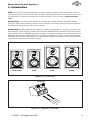
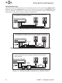
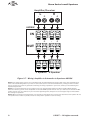
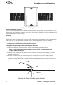
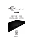
Storm Series
In-Wall Speakers
A60W/A61W/A62W/A82W/A82SW
www.atonhome.com
Storm Series In-wall Speakers
1. Introduction
ATON Thank you for choosing ATON Storm Series Outdoor speakers. All models were voiced in
our sound labs by musicians with years of critical listening experience and crafted for your listening enjoyment. To see the complete line of ATON products, visit us online at www.atonhome.
com.
Storm Series All in-wall models feature 1” pivoting wave guide tweeters, excellent off-axis
response, high power handling, custom driver materials, and network components that provide
the best price/performance ratio in the industry.
Storm Series In-Wall Speakers are available in several configurations - for stereo or Home Theater listening, install two-way models like the A60W, A61W, A62W or A82W. For the bass enthusiast, install a pair of A82W 8" speakers for deep, rich, thumping bass at any volume level! Use
A82SW In-Wall Passive Subwoofers for Low-Frequency Effects in a Home Theater. ATON In-Wall
Speakers are rated for safe outdoor use, and can be installed on porches, sunrooms and decks
to provide amazing sound outdoors, as well.
80
120 180
X
O
V
E
R
A60W/A61W
A62W
A82SW
A82W
Figure 1.1 - Front View
All Models
+
-
Figure 1.2 - Speaker Terminals
© 2007 • All rights reserved.
1
Storm Series In-wall Speakers
2. System Design/Applications
ATON In-Wall speakers are designed primarily to be installed in wall composed of drywall, but it
is possible to install them in other materials. Prior to installation, it is essential to determine the
type of application, and, therefore, the placement of the speakers in the wall. There are two typical applications that ATON In-Wall speakers will be used for: Stereo and Home Theater.
Stereo
In areas that have a defined listening area where two speakers will be mounted more or less
equidistant from each other, use a stereo setup with left and right speakers each connected
to their own channel of a stereo receiver or amplifier. This application provides the best sound
quality, staging, and depth possible in areas with a defined listening position. Figure 2.1 shows
an example of a stereo listening area.
X
Figure 2.1 - Stereo Application
Home Theater
ATON IN-wall Speakers provide unobtrusive, high-quality Home Theater sound when installed in
the correct locations. It is critical to identify the primary listening position before installation! See
Figure 2.2 for a system design utilizing in-wall speakers with an active subwoofer and Figure 2.3
for a system design utilizing In-wall speakers and passive in-wall subwoofers (A82SW).
TV
Active
Subwoofer
OR
OR
Figure 2.2 - 5.1 Home Theater Application w/ Active Subwoofer
2
©2007 • All rights reserved.
Storm Series In-wall Speakers
TV
80
120 180
X
O
V
E
R
A82SW
80
120 180
X
O
V
E
R
A82SW
OR
OR
Figure 2.3 - 5.1 Home Theater Application w/ Passive Subwoofers (A82SW)
3. Installation
The Installation process is divided into three distinct processes: Wiring, Mounting and Setting Switches. After carefully considering the intended application (Defining a Listening Area,
Mono/Stereo, Home Theater, etc.), specific mounting locations can be decided upon. Once the
specific locations are determined, installation can commence.
Wiring
Before actually running any wire or cable, take the time to look around each room or area of the
house and plan your wire paths for maximum efficiency. Look for routes through uncluttered
parts of the stud wall or ceiling that allow you to group all low-voltage (video, speaker wires,
Cat-5, telephone, etc.) wires wherever possible. It is a good practice to label both ends of all
cables and to protect wires by tying a plastic bag over the ends.
Label
Plastic Bag
LEFT
SPK
Figure 3.1 - Wiring Label & Plastic Bag
© 2007 • All rights reserved.
3
Storm Series In-wall Speakers
Wiring Methodology
There are three common scenarios for connecting speakers to an audio system. Figures 3.2 to
3.4 show stereo pairs, Figure 3.5 shows a Home Theater wiring scheme, and Figure 3.6 shows
passive subwoofer wiring. Figure 3-7 depicts the wiring method when using an A82SW Passive
Subwoofer and two stereo speakers (Sub/Sat configuration).
• Two separate 2 conductor speaker wires run from the A/V Receiver
or amplifier to each stereo speaker.
A/V Receiver/Amplifier
+
+
+
+
-
-
-
-
Figure 3.2 - Wiring: Amplifier to Speakers-2 Conductor Direct
• One 4-conductor speaker wire runs from the amplifier to a splice near
one speaker. A 2-conductor wire runs from the splice to each speaker.
A/V Receiver/Amplifier
Splice
4
Conductor
Wire
+
+
+
+
-
-
2
Conductor
Wire
-
-
Figure 3.3 - Wiring: Amplifier to Speakers-4 Conuctor to 2 Conductor
• One 4 conductor speaker wire runs from the amplifier to a stereo
volume control, then one 2 conductor speaker wire runs to each
stereo speaker.
A/V Receiver/Amplifier
Volume
Control
4
Conductor
Wire
+
+
+
+
-
-
-
-
2
Conductor
Wire
Figure 3.4 - Wiring: Amplifier to Speakers w/ Volume Control
4
©2007 • All rights reserved.
Storm Series In-wall Speakers
• Five 2 conductor speaker wires run from the A/V Receiver
to each surround sound speaker.
A/V Receiver/Amplifier
Figure 3.5 - Wiring: Amplifier to Speakers-Home Theater
• One 4 conductor speaker wire runs from the A/V Receiver
to the A82SW Passive Subwoofer then one 2 conductor
speaker wire runs to each of two stereo speakers.
A/V Receiver/Amplifier
80
L
R
+
+
120 180
X
O
V
E
R
+
-
+
A82SW
Figure 3.6 - Wiring: Amplifier to Speaker-Passive Subwoofer
© 2007 • All rights reserved.
5
Storm Series In-wall Speakers
Amplifier/Receiver
L
R
+
-
-
+
-
+
-
+
-
+
-
+
A82SW
IN
OUT
L Speaker R Speaker
Figure 3.7 - Wiring: Amplifier to Subwoofer to Speakers-A82SW
Note 1: Low voltage wiring must be run in accordance with the National Electrical Code as well as any other applicable provisions of the local building codes in your area. In some cases (such as commercial installations), running the wire in conduit
may be required. If you have any questions concerning the wiring of speakers in your home, contact your local building and
inspection department.
Note 2: It is recommended that you use quality CL-2 or CL-3 rated stranded speaker wire when installing ATON speakers.
Solid-core “Romex” type wire is not acceptable! Use at least 16AWG speaker wire for runs up to 100 feet, and at least 14 AWG
speaker wire for runs up to 200 feet. If you must cross high-voltage lines, always do so at a 90 degree angle to avoid audible
hum through the speakers!.
Note 3: When pre-wiring for In-wall speakers, it is essential to make direct wire runs from the head-end to each speaker. Do not
run speaker wires in series or parallel, and do not “daisy-chain” speakers to common wiring.
6
©2007 • All rights reserved.
Storm Series In-wall Speakers
Pre-Wiring
The audio/speaker cable runs should be routed from the head-end location (where the amplifier
or A/V Receiver is located) to the speaker rough-in brackets (if used). At the speaker locations,
securely fasten the speaker wire to the speaker rough-in bracket. If not using speaker rough-in
brackets, staple speaker wire runs in a loose zigzag between the studs where the speaker is
to be mounted to make it easier to find the cable after the drywall is installed. Zig-zagging the
cable also allows flexibility in the placement of the speaker.
Note: Do not run speaker wires closer than 12" from high voltage wires.
Min
12”
High
Voltage
Wiring
Speaker
Wire
Figure 3.8 - Pre-Wiring
Mounting
Two situations that can exist when mounting In-wall speakers:
• Pre-Construction - Installations that occur in new homes being built and in remodel
situations where walls and/or ceilings will be exposed.
• Retro-Fit - Installation that involve existing homes with walls and ceilings finished.
While the end result of either type of installation is similar, the process is quite different.
Pre-Construction
In a pre-construction installation, walls and ceilings are open with no drywall installed. This is
desirable and allows the installer much greater access than in retro-fit applications. ATON model
BK6W Rough-In Brackets are specifically designed to work with models A60W, A61W and A62W
while model BK8W Rough-In Brackets are designed to work with A82W and A82SW speakers.
Rough-in Brackets should be used whenever possible to reserve a neat hole in the drywall,
ensuring proper placement of speakers and making trim-out and final installation neat and
organized.
© 2007 • All rights reserved.
7
Storm Series In-wall Speakers
Figure 3.9 - Rough-In Bracket
Mounting Rough-In Brackets
Once the mounting locations are decided upon, assemble the brackets and secure them to the
ceiling joists using flat-head screws or heavy-duty staples (see the ATON Ceiling/In-Wall Rough-In
Brackets Manual for detailed steps).
Retro-Fit
Retro-fit installations are more difficult to complete than pre-construction because walls and
ceilings are intact. Typically wires must be fished into position through walls, floors and ceilings.
Holes must be cut and speakers mounted directly in the wall with no rough-in brackets.
Note: Before cutting holes in any existing wall or ceiling surface, probe the cavity behind
each speaker’s installation location for obstructions!
Cutting Speaker Openings in Walls (No Rough-in Brackets)
1. Use a stud finder to locate the studs around the intended speaker location.
Note: A stud-finding device may not detect pipes, wiring, or other obstructions
located behind the drywall.
2. Use the inside portion of the speaker cutout template (included in packaging) to confirm
speaker placement.
3. Remove templates and drill or carefully punch a pilot hole in the wall. A bent piece of
wire or a coat hanger may be use to probe the stud bay for obstructions. If you experience
resistance of any kind–STOP! If any obstructions are detected, patch the pilot hole and try
again in another location.
Ceiling
Pilot Hole
Wire or
Coat Hanger
Figure 3.10 -Probe Stud Bay Before Cutting!
8
©2007 • All rights reserved.
Storm Series In-wall Speakers
4. Once it has been determined that the cavity is free from obstructions, position the cutout
template and use a pencil to lightly trace the perimeter of the template.
5. Cut the opening using a keyhole saw, drywall router, or razor knife.
Mounting Speakers in Wall (Pre-Construction or Retro-Fit)
1. Remove speaker grille and place speaker face down.
2. Locate the speaker wire and pull through the wall opening.
3. Connect the speaker wire. BE SURE TO OBSERVE CORRECT POLARITY!
4. Insert the speaker into the opening in the wall (or Rough-in Bracket opening) and carefully tighten each of the six clamping screws, alternating diagonally between each screw
position to ensure proper fit.
5. Aim the pivoting tweeter at the listening area.
7. Set the Treble or XOVER switch if applicable. See Setting Switches for details.
8. Replace the speaker grille.
Figure 3.11 -Mounting Speakers In Wall
© 2007 • All rights reserved.
9
Storm Series In-wall Speakers
Setting Switches
A62W/A82W TREBLE Switch
Once the speakers are wired, mounted, and positioned correctly, use the TREBLE switch (if
applicable) to fine-tune the speakers based on local environmental variables such as hardwood
floors, thick draperies, etc. Select the “+” position to increase Treble response or select the “-”
position if no increase is desired.
TREBLE
Figure 3.12 -TREBLE Switch
A82SW XOVER SWITCH
The Crossover switch adjusts the upper frequency limit of sound that emanates from the subwoofer. This switch has three positions: 80Hz, 120Hz, and 180Hz. Correctly setting the XOVER
level is paramount to a smooth transition between the main speakers and the subwoofer. Setting this switch too low causes a gap to occur in the audio that makes the main speakers seem
disconnected from the bass, an audible separation of sound that does not seem natural. Setting
the switch too high causes bass to be produced too strongly because of overlapping frequencies
between the main speakers and subwwoofer. This causes a “muddy” sound and reduces the
overall clarity of the audio.
It is important to experiment with the XOVER switch upon initial setup to obtain the clearest,
smoothest sound possible. Try all three settings, and leave the switch in the location it
sounds best. See Figure 3-13.
80
120 18
0
X
O
V
E
R
Figure 3.13 -XOVER Switch
10
©2007 • All rights reserved.
Storm Series In-wall Speakers
4. Specifications
A60W
System Type....................................................................................................................................................................... 2-Way
Woofer........................................................................................................................................................ 6-1/2" Polypropylene
Tweeter ............................................................................................................................................................. 1" Pivoting Mylar
Crossover ...................................................................................................................................................................6dB/Octave
Impedance ....................................................................................................................................................................... 8 Ohms
Sensitivity ............................................................................................................................................................................ 90dB
Frequency Response ........................................................................................................................................45Hz to 20kHz
Power Handling .......................................................................................................................................................... 75 Watts
Cutout Dimensions ................................................................................................. 7-1/8" x 12-1/4" (181mm x 311mm)
Outer Frame Dimensions ................................................................................ 8-5/8" x 13-13/16" (218mm x 351mm)
Mounting Depth ............................................................................................................................................ 3-5/16” (83mm)
Pre-Construction Bracket ............................................................................................................................................. BK6W
A61W
System Type....................................................................................................................................................................... 2-Way
Woofer.......................................................................................................................................................... 6-1/2" Polypropylene
Tweeter .................................................................................................................................................... 1" Pivoting Silk Dome
Crossover ...................................................................................................................................................................6dB/Octave
Impedance .......................................................................................................................................................................8 Ohms
Sensitivity ............................................................................................................................................................................. 91dB
Frequency Response ........................................................................................................................................36Hz to 20kHz
Power Handling ....................................................................................................................................................... 100 Watts
Cutout Dimensions ................................................................................................. 7-1/8" x 12-1/4" (181mm x 311mm)
Outer Frame Dimensions ................................................................................ 8-5/8" x 13-13/16" (218mm x 351mm)
Mounting Depth ...............................................................................................................................................3-3/4” (94mm)
Pre-Construction Bracket ........................................................................................................................................... BK6W
A62W
System Type....................................................................................................................................................................... 2-Way
Woofer.........................................................................................................................6-1/2" Injection Molded Graphite (IMG)
Tweeter .................................................................................................................................................... 1" Pivoting Aluminum
Crossover ................................................................................................................................................................ 12dB/Octave
Switches .............................................................................................................................................................2 Position Treble
Impedance .......................................................................................................................................................................8 Ohms
Sensitivity ............................................................................................................................................................................. 91dB
Frequency Response ........................................................................................................................................34Hz to 20kHz
Power Handling ....................................................................................................................................................... 115 Watts
Cutout Dimensions ................................................................................................. 7-1/8" x 12-1/4" (181mm x 311mm)
Outer Frame Dimensions ................................................................................ 8-5/8" x 13-13/16" (218mm x 351mm)
Mounting Depth ...............................................................................................................................................3-3/4” (94mm)
Pre-Construction Bracket ............................................................................................................................................. BK6W
A82W
System Type....................................................................................................................................................................... 2-Way
Woofer................................................................................................................................. 8" Injection Molded graphite (IMG)
Tweeter ..................................................................................................................................................... 1" Pivoting Aluminum
Crossover ................................................................................................................................................................ 12dB/Octave
Switches .............................................................................................................................................................2 Position Treble
Impedance .......................................................................................................................................................................8 Ohms
Sensitivity ............................................................................................................................................................................ 92dB
Frequency Response ........................................................................................................................................30Hz to 22kHz
Power Handling ....................................................................................................................................................... 150 Watts
Cutout Dimensions .............................................................................................. 8-5/8" x 15-3/16" (219mm x 386mm)
Outer Frame Dimensions .............................................................................. 10-1/8" x 16-11/16" (257mm x 424mm)
Mounting Depth .................................................................................................................................................... 4” (101mm)
Pre-Construction Bracket ............................................................................................................................................. BK8W
A82SW
System Type............................................................................................................................................................... Subwoofer
Woofer................................................................................................................................. 8" Injection Molded graphite (IMG)
Crossover ................................................................................................................................. High Pass to Satellite Switches
Switches ......................................................................................................................................... 80/120/180 LPF Selection
Impedance .......................................................................................................................................................................8 Ohms
Sensitivity ............................................................................................................................................................................ 93dB
Frequency Response ........................................................................................................................................20Hz to 200Hz
Power Handling ....................................................................................................................................................... 200 Watts
Cutout Dimensions .............................................................................................. 8-5/8" x 15-3/16" (219mm x 386mm)
Outer Frame Dimensions .............................................................................. 10-1/8" x 16-11/16" (257mm x 424mm)
Mounting Depth .................................................................................................................................................... 4” (101mm)
Pre-Construction Bracket .............................................................................................................................................. BK8W
© 2007 • All rights reserved.
11
Storm Series In-wall Speakers
Notes:
12
©2007 • All rights reserved.
Limited Lifetime Warranty
ATON warrants to the purchaser/end user (“you”) that all Storm Series Speakers are to be free
from defects in materials and workmanship. This warranty is transferable to subsequent owners
of the product as long as the original proof of purchase is retained. If you discover a defect in
material or workmanship, you can obtain warranty service by contacting ATON at (859)-4227137 or [email protected]. If ATON determines that the product is in fact defective, ATON
shall, at its option, repair or replace the product free of charge to you. This warranty shall not
apply (a) to equipment not manufactured by ATON, (b) to equipment which was improperly installed, (c) which was repaired or altered by others than ATON, or its authorized representatives
or subject to unauthorized tampering, alteration, or modification, (d) damaged due to misuse,
negligence, accident, acts of God (including, but not limited to, excess moisture, insects, lightning, flood, electrical surge, tornado, earthquake, or other catastrophic events beyond ATON’s
control), or (e) subject to improper operation, maintenance or storage, or unreasonable use. The
foregoing warranties do not cover reimbursement for labor, transportation, removal, installation
or other expenses which may be incurred in connection with repair or replacement. The foregoing remedies shall be your exclusive remedies for any breach of warranty. Further, the foregoing warranty does not extend to equipment sold, but not manufactured by, ATON (“Third Party
Products”). With respect to any Third Party Products, the warranty for such product shall be as
provided by the manufacturer of such product, who will also be responsible for warranty service,
and ATON will pass through to you any transferable warranty actually extended to ATON by the
manufacturer.
THE FOREGOING WARRANTIES ARE EXCLUSIVE AND IN LIEU OF ALL OTHER EXPRESSED AND IMPLIED WARRANTIES. ATON EXPRESSLY DISCLAIMS ALL SUCH OTHER WARRANTIES, INCLUDING
BUT NOT LIMITED TO IMPLIED WARRANTIES OF MERCHANTABILITY, FITNESS FOR A PARTICULAR
PURPOSE AND NON-INFRINGEMENT. Notwithstanding the above, where applicable, if you qualify
as a “consumer” under the Magnuson-Moss Warranty Act, then you may be entitled to any implied warranties allowed by law for the Warranty Period. Some states do not allow limitations on
how long an implied Limited Warranty lasts, so the above limitation may not apply to you.
ATTENTION: TO OUR VALUED CONSUMERS
Valid proof of purchase is required for all warranty services. Warranty service requests made
without proof of date of purchase will be denied. Please keep the original sales receipt for your
records and send a copy to request warranty service. This warranty gives you specific legal
rights, and you may also have other rights which vary state to state.
*ATON is a division of ELAN Home Systems, LLC.
www.atonhome.com
or
[email protected]
P/N 9900932 REV:A