1
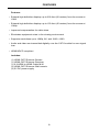
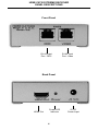
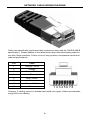
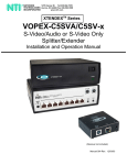
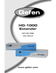
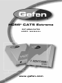
®
HDMI® CAT5 Extreme
EXT-HDMI-CAT5X
USER
MANUAL
www.gefen.com
ASKING FOR ASSISTANCE
Technical Support:
Telephone
Fax
(818) 772-9100
(800) 545-6900
(818) 772-9120
Technical Support Hours:
8:00 AM to 5:00 PM Monday through Friday Pacific Time
Write To:
Gefen, LLC
C/O Customer Service
20600 Nordhoff St.
Chatsworth, CA 91311
[email protected]
www.gefen.com
Notice
Gefen, LLC reserves the right to make changes in the hardware, packaging and any
accompanying documentation without prior written notice.
HDMI CAT5 Extreme is a trademark of Gefen, LLC
All trademarks are the property of their respective owners.
© 2008-2010 Gefen, LLC, All Rights Reserved
Rev X2
TABLE OF CONTENTS
1.
Introduction / Operation Notes
2.
Features
3.
HDMI CAT5 Extreme Sender Panel Descriptions
4.
HDMI CAT5 Extreme Receiver Panel Descriptions
5.
Connecting And Operating The HDMI CAT5 Extreme
6.
Dip Switch Usage Guide
7.
Wiring Diagram
8.
Network Cable Wiring Diagram
9.
Mounting Plate Installation
10. Specifications
11. Warranty
INTRODUCTION
The HDMI CAT5 Extreme extends your HDTV display up to 200 feet (60m) away
from your HDTV source using two CAT-5 cables. It is equipped with HDMI® (high
definition multimedia interface) connectors and is capable of supporting DVI (digital
visual interface) equipment when used with a HDMI to DVI Adapter, providing
greater flexibility and options when integrating several home theater components
How It Works
The HDMI CAT-5 Extender sender unit sits next to your computer, set-top box or
DVD player source. Cables supplied with the HDMI CAT5 Extreme connect your DVI
or HDMI source to the send unit. The HDMI CAT-5 Extender receive unit sits next
to your HDTV display - up to 200 feet (60m) away. The display plugs into the back
of the HDMI CAT-5 Extender receiver unit. Two CAT-5 cables the sender and the
receiver units to each other.
OPERATION NOTES
READ THESE NOTES BEFORE INSTALLING OR
OPERATING THE HDMI CAT5 EXTREME
•
The HDMI CAT5 Extreme is housed in a metal box for better RF shielding
•
For 1080i video, your CAT-5, CAT5e or CAT-6 cable should not exceed 200 feet
(60m)
•
For 1080p video, your CAT-5, CAT5e or CAT-6 cable should not exceed 150
feet (45m)
1
FEATURES
Features
• Extends high definition displays up to 200 feet (60 meters) from the source at
1080i
• Extends high definition displays up to 150 feet (45 meters) from the source at
1080p
• Improved compensation for cable skew
• Eliminates equipment noise in the viewing environment
• Supports resolutions up to 1080p, 2K, and 1920 x 1200
• Audio and video are transmitted digitally over the CAT-5e cable for zero signal
loss
• HDMI/HDCP compliant
Includes:
(1) HDMI CAT5 Extreme Sender
(1) HDMI CAT5 Extreme Receiver
(1) 6 ft HDMI to HDMI Cable M-M
(2) HDMI CAT5 Extreme Wall mounts
(2) 5V DC power supply
2
HDMI CAT5 EXTREME SENDER
PANEL DESCRIPTIONS
Front Panel
RJ-45 Input
Port - Video
RJ-45 Input
Port - DDC
Back Panel
5V DC
Power Input
Power LED
Indicator
3
HDMI In
HDMI CAT5 EXTREME RECEIVER
PANEL DESCRIPTIONS
Front Panel
RJ-45 Input
Port - DDC
RJ-45 Input
Port - Video
Back Panel
HDMI Out
Power LED
Indicator
4
5V DC
Power Input
CONNECTING AND OPERATING
THE HDMI CAT5 EXTREME
How to Connect the HDMI CAT5 Extreme
1
Connect your source to the HDMI CAT5 Extreme sender unit using the
supplied HDMI cable.
2
Connect your display to the HDMI CAT5 Extreme receiver unit using a user
supplied HDMI cable.
3
Connect the HDMI CAT5 Extreme sender and receiver units together using a
user supplied CAT-5e cable.
4
Plug the included 5V DC power supplies into the HDMI CAT5 Extreme sender
and receiver units.
5
If there is no image or video noise on the display, please refer to the DIP
SWITCH Usage Guide in the following section to adjust the video signal.
* Please ensure that all cables are properly connected. Gefen recommends
TIA/EIA-568-B specifications for all CAT-5, CAT-5e or CAT-6 terminations.
Please see page more 8 for details.
5
DIP SWITCH USAGE GUIDE
The sender and receiver of the HDMI CAT5 Extreme both contain a set of DIP
SWITCHES located underneath each unit. Peeling back the silver sticker on the
bottom of each unit will reveal the DIP SWITCH bank. These service switches are
used to boost and equalize the signal to best match the conditions in your setup.
(*Note: Adjustments should be done with the source and display on. Switches 3 and
4 on both sender and receiver banks are not used.)
Sender DIP SWITCH Settings
Setting
Switch 1 Switch 2
No Boost
OFF
ON
Normal Boost (Default)
OFF
OFF
Strong Boost
ON
OFF
Undefined
ON
ON
Receiver DIP SWITCH Settings
Setting
Switch 1 Switch 2
No EQ (Default)
OFF
OFF
EQ Setting 2
ON
OFF
EQ Setting 3
OFF
ON
Maximum EQ
ON
ON
Adjustment Guidelines:
1.
Strong boost should not be used on stranded cables. A strong boost will cause
pixelation or no picture on these cables.
2.
Using the wrong settings will not damage the units; it will either produce no
image or a noisy image.
3.
To eliminate the possibility of cross talk and interference, cables must be
terminated with TIA/EIA-568-B specifications.
6
HDMI
CAT5e
WIRING DIAGRAM
7
NETWORK CABLE WIRING DIAGRAM
Gefen has specifically engineered their products to work with the TIA/EIA-568-B
specification. Please adhere to the table below when field terminating cable for
use with Gefen products. Failure to do so may produce unexpected results and
reduced performance.
Pin
Color
1
Orange / White
2
Orange
3
Green / White
4
Blue
5
Blue / White
6
Green
7
Brown / White
8
Brown
12345678
Category 5 cabling comes in stranded and solid core types. Gefen recommends
using solid core cabling.
8
MOUNTING PLATE INSTALLATION
9
SPECIFICATIONS
Video Amplifier Bandwidth ............................................................................ 165 MHz
Input Video Signal ................................................................................... 1.2 Volts p-p
Input DDC Signal .............................................................................. 5 Volts p-p (TTL)
Single Link Range .......................................................................1080p / 1920 x 1200
HDMI Connector Type ............................................................... Type A 19 pin female
Link Connector .................................................................................................. RJ-45
Power Consumption ........................................................................... 20 Watts (max)
Power Supply ................................................................................................... 5V DC
Dimensions ....................................................................... 3.4” W x 1.25” H x 3.25” D
Shipping Weight ................................................................................................. 3 lbs.
10
11
Rev X2
20600 Nordhoff St., Chatsworth CA 91311
1-800-545-6900
818-772-9100
www.gefen.com
Pb
fax: 818-772-9120
[email protected]