1
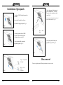
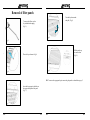
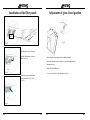
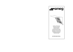
Libretto d’istruzioni
Instruction manual
Mode d’emploi
Gebrauchsanweisung
Manual de instrucciones
Instruções de instala ção
Gebruiksaanwijzingen
Bruksanvisning
KTS75/KTS75C
Installation of glass panels
Fig.4
Get the glass panel with no logo and
place it near the hood 2, centre the
four pins in the remaining four hood
seats (Fig.4).
Take the two 200x750 hood glass panels out
of the box.
(2) For proper positioning, check the position of
the metal frame on the back (Fig.4.1).
Remove them from the box with care.
Open the hood upper glass panel (Fig.1).
Fig.1
Fig.4.1 – Rear
view.
Take the glass panel with the SMEG
logo close to the hood and centre the
four hinges in their seats (Fig.2).
Fig.2
Let the glass panel slide along the
pin guides (Fig.5 and Fig.3.2)
Let the glass panel slide downwards
along the pin guides (Fig.3.2).
Fig.5
Glass removal
Fig.3.1 - Initial position
(Pins high)
To remove the glass panels, follow the procedure in the reverse order.
Fig.3
EN
Fig.3.2 - Final
position
(Pins down)
01
EN
02
Removal of filter panels
Turn the key downwards
and pull (Fig.8).
To remove the filters, use the
key included in the supply
(Fig.5).
Fig.8
Fig.5
Pull the panels up
to remove them
(Fig.9).
Place the key as shown in Fig.6.
Fig.9
Fig.6
NB.: To remove the upper panel pair, remove the glass panels as described on page 2 .
Insert the key prongs in the holes on
the upper central part of the panel
(Fig.7) .
Fig.7
EN
03
EN
04
Installation of the filter panels
Adjustment of glass-closed position
Fig.13
Fig.10
Take the panels close to the hood.
Insert the filter pins in the seats as
shown in Fig.10
Adjust the glass closed position after installing the hood.
Adjust the closing position of the glass by loosening/tightening the
adjustment screws.
Adjust the LH and RH sides.
Fig.11
Use a size-3 Allen key for the adjustment (Fig.13).
Rotate the panels and take them
close to the hood (Fig.11 and
Fig,12).
Fig.12
EN
05
EN
06
Installation instructions
Reference
height for the
center of the
exhaust hole
Height of the
holes for the
bracket
Level of the
hob
Fig.14
Fig.15
a) Fix the hood in the center over the hob;
b) Maintain the distances shown at fig. 14 and fig. 15.
EN
07